
SPLIT-TYPE AIR CONDITIONERS Full Product Line Catalogue 2015
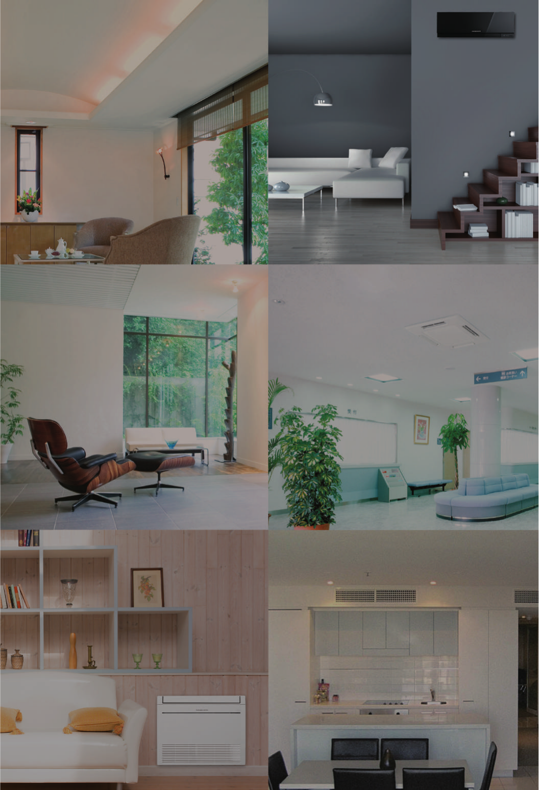
Wrap Yourself in Comfort and Quiet
Eco-conscious Technologies from Japan
Full Product Line Catalogue
2016
TENTATIVE
NOTICE
■ Do not install indoor units in areas (e.g. mobile phone base stations) where the emission of VOCs such as phthalate
compounds and formaldehyde is known to be high as this may result in a chemical reaction.
■ Our air-conditioning equipment and heat pumps contain a fluorinated greenhouse gas, R410A.
■ When installing or relocating or servicing our air-conditioning equipment, use only the specified refrigerant
(
R410A
)
to charge
the refrigerant lines.
Do not mix it with any other refrigerant and do not allow air to remain in the lines.
If air is mixed with the refrigerant, then it can be the cause of abnormal high pressure in the refrigerant lines, and may result
in an explosion and other hazards.
The use of any refrigerant other than that specified for the system will cause mechanical failure, system malfunction or unit
breakdown. In the worst case, this could lead to a serious impediment to securing product safety.
Eco Changes is the Mitsubishi Electric Group’s environmental statement,
and expresses the Group’s stance on environmental management.
Through a wide range of businesses, we are helping contribute to the
realization of a sustainable society.
S-179-5-C9521-C SI1511 Printed in Japan (IP)
Revised Publication, effective Nov. 2015.
Superseding Publication, S-179-5-C9521-B of Apr. 2015.
Specifications are subject to change without notice.

Core Environmental Policy
The Mitsubishi Electric Group promotes sustainable development and is
committed to protecting and restoring the global environment through technology,
through all its business activities, and through the actions of its employees.
Doing Our Part to
Create a Better Future for All...
Environmental Vision 2021
Ensuring Harmony with Nature Fostering Environmental Awareness
Preventing Global Warming
lReduce CO2 emissions from product usage by 30%
lReduce total CO2 emissions from production by 30%
lAim to reduce CO2 emissions from
power generation
Making Positive Contributions to the Earth
and its People through Technology and Action
Creating a Recycling-Based Society
lReduce, reuse and recycle “3Rs” products
reduce resources used by 30%
lZero emissions from manufacturing reducing
the direct landfill of waste to zero

2
Mitsubishi Electric reflects the essence of this policy and vision
in all aspects of its air conditioner business as well.
* WEEE and RoHS directives: The Waste Electrical and Electronic Equipment (WEEE) Directive is a recycling directive for this
type of equipment, while the Restrictions of Hazardous Substances (RoHS) Directive is an EU directive restricting the use of six
specified substances in electronic and electrical devices. In the EU, it is no longer possible (from July 2006) to sell products
containing any of the six substances.
Creating a Recycling-Based Society
In striving to heighten the eco-awareness of its employees, Mitsubishi Electric provides
education in RoHS, WEEE and other environmental regulations, along with environmental
education targeting second and third-year workers.
1. Inverter
2. 3D i-see Sensor
3. Flash Injection
Comfort Ecology
Faster start-up and more
stable indoor temperature
than non-inverter units.
Fewer On/Off operations
than with non-inverter, saving
energy.
Since the positions of people
can be detected, airflow can
be set to personal taste, such
as in airflow path or protected
from the wind. The ability to
adjust to individual
preferences realizes more
comfortable air conditioning.
Since the number of people in a
room can be detected,
energy-saving operation is
adjusted or the power is turned
off automatically. Efficient air
conditioning with less waste is
realized.
Achieves high heating
capacity even at low
temperatures, plus faster
start-up compared to
conventional inverters.
Expands the region covered by
heat pump heating system.
Mitsubishi Electric develops technologies to balance comfort and ecology,
achieving greater efficiency in heat pump operation.
Preventing Global Warming
Heat pump technology inspires Mitsubishi Electric to design air conditioners
that harmonize comfort and ecology.
Heat Pump Principle (When Heating) <Case of COP 4.0>
Refrigerant and Heat Circulation
Outdoors
“4kW”
Heat absorbed
from the air
Indoors
Expansion valve expands
refrigerant to lower the temperature
Compressor
Expansion valve
Evaporator Condenser
Compressor compresses
refrigerant to raise
the temperature
“4kW”
Heat output
5
o
C
50
o
C
80
o
C
10
o
C
60
o
C
“1kW”
20
o
C
30
o
C
40
o
C
Electrical
Energy Input
Electrical
Energy Input
Heat
1. All models are designed for RoHS and WEEE compliance. *
2. Mitsubishi Electric develops downsizing technology to reduce materials use.
Ensuring Harmony with Nature / Fostering Environmental Awareness
C
ONTENTS
LINE-UP
NEW ECODESIGN DIRECTIVE
INVERTER TECHNOLOGIES
FEATURES
FUNCTION LIST
CONTROL TECHNOLOGIES
M SERIES
S SERIES
P SERIES
MULTI SPLIT SERIES
POWERFUL HEATING SERIES
OPTIONAL PARTS
EXTERNAL DIMENSIONS
PIPING INSTALLATION
FEATURES & SPECIFICATIONS
FEATURES & SPECIFICATIONS
005-008
009-010
011-012
013-020
021-024
025-030
031-052
053-060
061-086
087-096
097-114
115-120
121-136
137-142
143-160
161-172
Air Conditioners
AIR-TO-WATER
LOSSNAY SYSTEM
3

C
ONTENTS
LINE-UP
NEW ECODESIGN DIRECTIVE
INVERTER TECHNOLOGIES
FEATURES
FUNCTION LIST
CONTROL TECHNOLOGIES
M SERIES
S SERIES
P SERIES
MULTI SPLIT SERIES
POWERFUL HEATING SERIES
OPTIONAL PARTS
EXTERNAL DIMENSIONS
PIPING INSTALLATION
FEATURES & SPECIFICATIONS
FEATURES & SPECIFICATIONS
005-008
009-010
011-012
013-020
021-024
025-030
031-052
053-060
061-086
087-096
097-114
115-120
121-136
137-142
143-160
161-172
Air Conditioners
AIR-TO-WATER
LOSSNAY SYSTEM
4
5
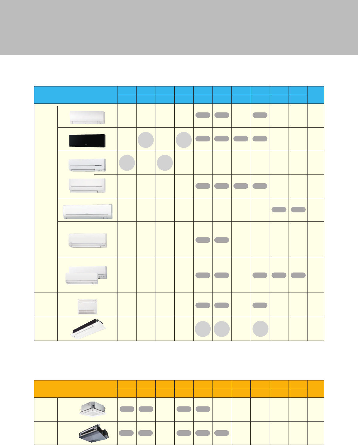
LINE-UP
Indoor Combinations
1 outdoor unit & 1 indoor unit
1 outdoor unit & 2 indoor units
1 outdoor unit & 3 indoor units
1 outdoor unit & 4 indoor units
SINGLE
TWIN
TRIPLE
QUADRUPLE
LINE-UP
INVERTER Models
INVERTER Models
INVERTER Models
M SERIES
MXZ SERIES
POWERFUL HEATING SERIES
Page
5.3kW
1-phase
7. 1kW
1-phase
8.3kW
1-phase
10.2kW
<1-phase>
8.3kW
<1-phase>
7. 2kW
<1-phase>
5.4kW
<1-phase>
5.3kW
<1-phase>
4.2kW
<1-phase>
3.3kW
<1-phase>
Model Name
Page
Model Name
1.5kW
1-phase
1.8kW
1-phase
2.0kW
1-phase
Wall-mountedCapacity ClassModel Name
4-way cassette
Wall-mounted
Floor-standing Cassette
up to 4 indoor units
MXZ-4E83VA
up to 4 indoor units
MXZ-4E72VA
up to 3 indoor units
MXZ-3E54VA
up to 2 indoor units
MXZ-2D53VA (H)
up to 2 indoor units
MXZ-2D42VA2
up to 2 indoor units
MXZ-2D33VA2
up to 6 indoor units
MXZ-6D122VA
up to 5 indoor units
MXZ-5E102VA
MFZ-KJ25/35/50
MLZ-KA25/35/50
SLZ-KF25/35/50
PLA-RP50/60/71
MFZ-KJ25/35/50
MLZ-KA25/35/50
SLZ-KF25/35/50
PLA-RP50/60/71
MFZ-KJ25/35/50
MLZ-KA25/35/50
SLZ-KF25/35/50
PLA-RP50/60
MFZ-KJ25/35/50
MLZ-KA25/35/50
SLZ-KF25/35/50
PLA-RP50
MFZ-KJ25/35
MLZ-KA25/35
MFZ-KJ25/35MLZ-KA25/35
MFZ-KJ25
MLZ-KA25
SLZ-KF25
Ceiling-concealed
Ceiling-suspended
12.2kW
<1-phase>
MFZ-KJ25/35/50
MLZ-KA25/35/50
SLZ-KF25/35/50
PLA-RP50/60/71
SEZ-KD25/35/50/60/71
PEAD-RP50/60/71
SEZ-KD25/35/50/60/71
PEAD-RP50/60/71
SEZ-KD25/35/50/60/71
PEAD-RP50/60/71
SEZ-KD25/35/50/60
PEAD-RP60
SEZ-KD25/35/50
PEAD-RP50
PCA-RP50/60/71
PCA-RP50/60/71
PCA-RP50/60
PCA-RP50
SEZ-KD25/35
SEZ-KD25/35
SEZ-KD25
6.0kW
1-phase
7. 1kW
1-phase
Wall-
mounted
Compact
oor
1-way
cassette
MSZ-F Series
MFZ Series
MLZ Series
MSZ-E Series
H : Outdoor unit with freeze-prevention heater is available.
S·B: Indoor units are available in three colours; Silver, Black and White.
H: Freeze-prevention heater is included as standard equipment.
4.2kW
1-phase
Wall-mounted
3.5kW
1-phase
SINGLE
MXZ
connection
only
5.0kW
1-phase
MXZ
connection
only
2.5kW
1-phase
SINGLE
MXZ
connection
only
2.2kW
1-phase
MXZ
connection
only
31
35
37
45
47
Compact oor
Multi split
2.5kW
1-phase
SINGLE
H
SINGLE
H
3.5kW
1-phase
SINGLE
H
SINGLE
H
5.0kW
1-phase
SINGLE
H
SINGLE
H
Page
99/105
99/107
99/108
101/109
110
103/111
89
PCA-RP50/60/71
89
89
89
6.8kW
<1-phase>
up to 3 indoor units
MXZ-3E68VA
MFZ-KJ25/35/50
MLZ-KA25/35/50
SLZ-KF25/35/50
PLA-RP50/60
SEZ-KD25/35/50/60
PEAD-RP60
PCA-RP50/60
89
89
89
89
89
Ceiling-concealed
10.0kW
1- & 3-phase
SINGLE
TWIN
SINGLE
TWIN
SINGLE
TWIN
12.5kW
3-phase
SINGLE
TWIN
SINGLE
TWIN
MSZ-S Series
MXZ
connection
only
MXZ
connection
only
37
SINGLE SINGLE
MSZ-G Series
37
S
·
B
S
·
B
MXZ
connection
only
S
·
B
SINGLE
S
·
B
SINGLE
S
·
B
SINGLE
S
·
B
SINGLE
HH
SINGLE SINGLE
SINGLE
H
SINGLE
H
SINGLE
H
ZUBADAN
MSZ-FH25/35/50
MSZ-EF18/22/25/35/42/50
MSZ-SF15/20/25/35/42/50
MSZ-GF60/71
MSZ-FH25/35/50
MSZ-EF18/22/25/35/42/50
MSZ-SF15/20/25/35/42/50
MSZ-GF60/71
MSZ-FH25/35/50
MSZ-EF18/22/25/35/42/50
MSZ-SF15/20/25/35/42/50
MSZ-GF60/71
MSZ-FH25/35/50
MSZ-EF18/22/25/35/42/50
MSZ-SF15/20/25/35/42/50
MSZ-GF60
MSZ-FH25/35/50
MSZ-EF18/22/25/35/42/50
MSZ-SF15/20/25/35/42/50
MSZ-GF60
MSZ-FH25/35/50
MSZ-EF18/22/25/35/42/50
MSZ-SF15/20/25/35/42/50
MSZ-FH25/35
MSZ-EF18/22/25/35/42/50
MSZ-SF15/20/25/35/42/50
MSZ-FH25/35
MSZ-EF18/22/25/35
MSZ-SF15/20/25/35
MSZ-FH25
MSZ-EF18/22/25
MSZ-SF15/20/25
8.3kW
<1-phase>
up to 4 indoor units
MXZ-4E83VAHZ
MFZ-KJ25/35/50
MLZ-KA25/35/50
SLZ-KF25/35/50
PLA-RP50/60/71
SEZ-KD25/35/50/60/71
PEAD-RP50/60/71
PCA-RP50/60/71 111
MSZ-FH25/35/50
MSZ-EF18/22/25/35/42/50
MSZ-SF15/20/25/35/42/50
MSZ-GF60/71
91
5.0kW
<1-phase>
up to 3 indoor units
MXZ-3DM50VA
MSZ-HJ25/35/50
MSZ-DM25/35
5.3kW
<1-phase>
up to 2 indoor units
MXZ-2E53VAHZ
MFZ-KJ25/35
MLZ-KA25/35
SLZ-KF25/35
SEZ-KD25/35 111
MSZ-FH25/35
MSZ-EF18/22/25/35/42/50
MSZ-SF15/20/25/35/42/50
SINGLESINGLE
SINGLE
PLA Series
MSZ-FH VEHZ Series
PKA Series
MFZ-KJ VEHZ Series
MXZ-E VAHZ Series
PEAD-JA Series
4.0kW
<1-phase>
up to 2 indoor units
MXZ-2DM40VA
MSZ-HJ25/35
MSZ-DM25/35
91
MSZ-D Series
SINGLESINGLE
41
2PORT
H
4PORT
H
INVERTER Models
S SERIES
Page
5.0kW4.2kW3.5kW2.5kW
Model Name
6.0kW7.1kW 8.0kW
1-phase1-phase1-phase1-phase 1-phase 1-phase 1-phase
10.0kW
1- & 3-phase
14.0kW
1- & 3-phase
20.0kW
1- & 3-phase
2 x 2
cassette
Compact
ceiling-
concealed
SLZ Series
SEZ Series
SINGLE SINGLE SINGLE SINGLE
SINGLE
L
SINGLE
L
SINGLE
L
SINGLE
L
SINGLE
L
L : Indoor units are available in two types; with or without the wireless remote controller.
55
59
MSZ-H Series
SINGLESINGLE
43
SINGLE SINGLESINGLE
MSZ-HJ60/71
MSZ-HJ25/35/50
6
LINE-UP
Indoor Combinations
1 outdoor unit & 1 indoor unit
1 outdoor unit & 2 indoor units
1 outdoor unit & 3 indoor units
1 outdoor unit & 4 indoor units
SINGLE
TWIN
TRIPLE
QUADRUPLE
LINE-UP
INVERTER Models
INVERTER Models
INVERTER Models
M SERIES
MXZ SERIES
POWERFUL HEATING SERIES
Page
5.3kW
1-phase
7. 1kW
1-phase
8.3kW
1-phase
10.2kW
<1-phase>
8.3kW
<1-phase>
7. 2kW
<1-phase>
5.4kW
<1-phase>
5.3kW
<1-phase>
4.2kW
<1-phase>
3.3kW
<1-phase>
Model Name
Page
Model Name
1.5kW
1-phase
1.8kW
1-phase
2.0kW
1-phase
Wall-mountedCapacity ClassModel Name
4-way cassette
Wall-mounted
Floor-standing Cassette
up to 4 indoor units
MXZ-4E83VA
up to 4 indoor units
MXZ-4E72VA
up to 3 indoor units
MXZ-3E54VA
up to 2 indoor units
MXZ-2D53VA (H)
up to 2 indoor units
MXZ-2D42VA2
up to 2 indoor units
MXZ-2D33VA2
up to 6 indoor units
MXZ-6D122VA
up to 5 indoor units
MXZ-5E102VA
MFZ-KJ25/35/50
MLZ-KA25/35/50
SLZ-KF25/35/50
PLA-RP50/60/71
MFZ-KJ25/35/50
MLZ-KA25/35/50
SLZ-KF25/35/50
PLA-RP50/60/71
MFZ-KJ25/35/50
MLZ-KA25/35/50
SLZ-KF25/35/50
PLA-RP50/60
MFZ-KJ25/35/50
MLZ-KA25/35/50
SLZ-KF25/35/50
PLA-RP50
MFZ-KJ25/35
MLZ-KA25/35
MFZ-KJ25/35MLZ-KA25/35
MFZ-KJ25
MLZ-KA25
SLZ-KF25
Ceiling-concealed
Ceiling-suspended
12.2kW
<1-phase>
MFZ-KJ25/35/50
MLZ-KA25/35/50
SLZ-KF25/35/50
PLA-RP50/60/71
SEZ-KD25/35/50/60/71
PEAD-RP50/60/71
SEZ-KD25/35/50/60/71
PEAD-RP50/60/71
SEZ-KD25/35/50/60/71
PEAD-RP50/60/71
SEZ-KD25/35/50/60
PEAD-RP60
SEZ-KD25/35/50
PEAD-RP50
PCA-RP50/60/71
PCA-RP50/60/71
PCA-RP50/60
PCA-RP50
SEZ-KD25/35
SEZ-KD25/35
SEZ-KD25
6.0kW
1-phase
7. 1kW
1-phase
Wall-
mounted
Compact
oor
1-way
cassette
MSZ-F Series
MFZ Series
MLZ Series
MSZ-E Series
H : Outdoor unit with freeze-prevention heater is available.
S·B: Indoor units are available in three colours; Silver, Black and White.
H: Freeze-prevention heater is included as standard equipment.
4.2kW
1-phase
Wall-mounted
3.5kW
1-phase
SINGLE
MXZ
connection
only
5.0kW
1-phase
MXZ
connection
only
2.5kW
1-phase
SINGLE
MXZ
connection
only
2.2kW
1-phase
MXZ
connection
only
31
35
37
45
47
Compact oor
Multi split
2.5kW
1-phase
SINGLE
H
SINGLE
H
3.5kW
1-phase
SINGLE
H
SINGLE
H
5.0kW
1-phase
SINGLE
H
SINGLE
H
Page
99/105
99/107
99/108
101/109
110
103/111
89
PCA-RP50/60/71
89
89
89
6.8kW
<1-phase>
up to 3 indoor units
MXZ-3E68VA
MFZ-KJ25/35/50
MLZ-KA25/35/50
SLZ-KF25/35/50
PLA-RP50/60
SEZ-KD25/35/50/60
PEAD-RP60
PCA-RP50/60
89
89
89
89
89
Ceiling-concealed
10.0kW
1- & 3-phase
SINGLE
TWIN
SINGLE
TWIN
SINGLE
TWIN
12.5kW
3-phase
SINGLE
TWIN
SINGLE
TWIN
MSZ-S Series
MXZ
connection
only
MXZ
connection
only
37
SINGLE SINGLE
MSZ-G Series
37
S
·
B
S
·
B
MXZ
connection
only
S
·
B
SINGLE
S
·
B
SINGLE
S
·
B
SINGLE
S
·
B
SINGLE
HH
SINGLE SINGLE
SINGLE
H
SINGLE
H
SINGLE
H
ZUBADAN
MSZ-FH25/35/50
MSZ-EF18/22/25/35/42/50
MSZ-SF15/20/25/35/42/50
MSZ-GF60/71
MSZ-FH25/35/50
MSZ-EF18/22/25/35/42/50
MSZ-SF15/20/25/35/42/50
MSZ-GF60/71
MSZ-FH25/35/50
MSZ-EF18/22/25/35/42/50
MSZ-SF15/20/25/35/42/50
MSZ-GF60/71
MSZ-FH25/35/50
MSZ-EF18/22/25/35/42/50
MSZ-SF15/20/25/35/42/50
MSZ-GF60
MSZ-FH25/35/50
MSZ-EF18/22/25/35/42/50
MSZ-SF15/20/25/35/42/50
MSZ-GF60
MSZ-FH25/35/50
MSZ-EF18/22/25/35/42/50
MSZ-SF15/20/25/35/42/50
MSZ-FH25/35
MSZ-EF18/22/25/35/42/50
MSZ-SF15/20/25/35/42/50
MSZ-FH25/35
MSZ-EF18/22/25/35
MSZ-SF15/20/25/35
MSZ-FH25
MSZ-EF18/22/25
MSZ-SF15/20/25
8.3kW
<1-phase>
up to 4 indoor units
MXZ-4E83VAHZ
MFZ-KJ25/35/50
MLZ-KA25/35/50
SLZ-KF25/35/50
PLA-RP50/60/71
SEZ-KD25/35/50/60/71
PEAD-RP50/60/71
PCA-RP50/60/71 111
MSZ-FH25/35/50
MSZ-EF18/22/25/35/42/50
MSZ-SF15/20/25/35/42/50
MSZ-GF60/71
91
5.0kW
<1-phase>
up to 3 indoor units
MXZ-3DM50VA
MSZ-HJ25/35/50
MSZ-DM25/35
5.3kW
<1-phase>
up to 2 indoor units
MXZ-2E53VAHZ
MFZ-KJ25/35
MLZ-KA25/35
SLZ-KF25/35
SEZ-KD25/35 111
MSZ-FH25/35
MSZ-EF18/22/25/35/42/50
MSZ-SF15/20/25/35/42/50
SINGLESINGLE
SINGLE
PLA Series
MSZ-FH VEHZ Series
PKA Series
MFZ-KJ VEHZ Series
MXZ-E VAHZ Series
PEAD-JA Series
4.0kW
<1-phase>
up to 2 indoor units
MXZ-2DM40VA
MSZ-HJ25/35
MSZ-DM25/35
91
MSZ-D Series
SINGLESINGLE
41
2PORT
H
4PORT
H
INVERTER Models
S SERIES
Page
5.0kW4.2kW3.5kW2.5kW
Model Name
6.0kW7.1kW 8.0kW
1-phase1-phase1-phase1-phase 1-phase 1-phase 1-phase
10.0kW
1- & 3-phase
14.0kW
1- & 3-phase
20.0kW
1- & 3-phase
2 x 2
cassette
Compact
ceiling-
concealed
SLZ Series
SEZ Series
SINGLE SINGLE SINGLE SINGLE
SINGLE
L
SINGLE
L
SINGLE
L
SINGLE
L
SINGLE
L
L : Indoor units are available in two types; with or without the wireless remote controller.
55
59
MSZ-H Series
SINGLESINGLE
43
SINGLE SINGLESINGLE
MSZ-HJ60/71
MSZ-HJ25/35/50
7
Page
SINGLESINGLE SINGLE SINGLE
SINGLE
SINGLE SINGLE
SINGLESINGLE
SINGLE
SINGLE
SINGLE
SINGLE SINGLESINGLE
SINGLE
TWIN
SINGLE
TWIN
SINGLE
TWIN
TWIN
SINGLE
TWIN
SINGLE
SINGLE
TWIN
TWIN
SINGLE
TWIN
SINGLE
TWIN
SINGLE
TWIN
SINGLE
TWIN
SINGLE
TWIN
TRIPLE
SINGLE
TWIN
SINGLE
TWIN
TWIN
TRIPLE
TWIN
TRIPLE
TWIN
TWIN
TRIPLE
TRIPLE
QUADRUPLE
TWIN
TRIPLE
TRIPLE
TWIN
TRIPLE
QUADRUPLE
TWIN
TRIPLE
TRIPLE
TWIN
TRIPLE
QUADRUPLE
TRIPLE
QUADRUPLE
LINE-UP
POWER INVERTER Models
P
SERIES
STANDARD INVERTER Models
3.5kW 5.0kW 6.0kW 7.1kW 10.0kW 12.5kW 14.0kW 25.0kW 40.0kW 50.0kW
1-phase 1-phase 1-phase 1-phase 1- & 3-phase 1- & 3-phase1- & 3-phase3-phase3-phase 3-phase
Wall-mounted
PCA-HAQ Series
Floor-standing
PSA Series
Model Name
Indoor Combinations
1 outdoor unit & 1 indoor unit
1 outdoor unit & 2 indoor units
1 outdoor unit & 3 indoor units
1 outdoor unit & 4 indoor units
4-way cassette
PLA Series
Ceiling-suspended
Ceiling-suspended
for Professional
Kitchen
✽ 1 indoor unit requires 2 outdoor units.
✽ 1 indoor unit requires 2 outdoor units.
Page
3.5kW 5.0kW 6.0kW 7.1kW 10.0kW 12.5kW 14.0kW 25.0kW 40.0kW 50.0kW
1-phase 1-phase 1-phase 1-phase 1- & 3-phase 1- & 3-phase1- & 3-phase3-phase3-phase 3-phase
Wall-mounted
PKA Series
PCA-KAQ Series
PCA-HAQ Series
Floor-standing
PSA Series
Model Name
4-way cassette
PLA Series
Ceiling-suspended
Ceiling-suspended
for Professional
Kitchen
PKA Series
PCA-KAQ Series
SINGLE
TWIN
TRIPLE
QUADRUPLE
SINGLE SINGLE SINGLE SINGLE
SINGLE
TWIN
SINGLE
TWIN
SINGLE
TWIN
TRIPLE
TWIN
TRIPLE
QUADRUPLE
SINGLE SINGLE SINGLE
SINGLE
TWIN
SINGLE
TWIN
SINGLE
TWIN
SINGLE
TWIN
TRIPLE
TWIN
TRIPLE
QUADRUPLE
PEAD-JA Series
PEA Series
Ceiling-concealed
SINGLE
✽
SINGLE
✽
SINGLE
SINGLE SINGLE SINGLE
SINGLE
TWIN
SINGLE
TWIN
SINGLE
TWIN
SINGLE
TWIN
TRIPLE
TWIN
TRIPLE
QUADRUPLE
PEAD-JA Series
PEA Series
Ceiling-concealed
SINGLE
✽
SINGLE
✽
SINGLE
SINGLE SINGLE SINGLE SINGLE
SINGLE
TWIN
SINGLE
TWIN
SINGLE
TWIN
TRIPLE
TWIN
TWIN
TRIPLE
QUADRUPLE
TWIN
TRIPLE
QUADRUPLE
TWIN
TRIPLE
QUADRUPLE
TWIN
TWIN
TRIPLE
QUADRUPLE
20.0kW
3-phase
20.0kW
3-phase
TWIN
TRIPLE
QUADRUPLE
TWIN
TRIPLE
QUADRUPLE
SINGLE
TWIN
TRIPLE
QUADRUPLE
SINGLE
TWIN
TRIPLE
QUADRUPLE
TWIN
TRIPLE
QUADRUPLE
65
76
79
80
71
74
65
76
79
80
84
71
74
84
8
Page
SINGLESINGLE SINGLE SINGLE
SINGLE
SINGLE SINGLE
SINGLESINGLE
SINGLE
SINGLE
SINGLE
SINGLE SINGLESINGLE
SINGLE
TWIN
SINGLE
TWIN
SINGLE
TWIN
TWIN
SINGLE
TWIN
SINGLE
SINGLE
TWIN
TWIN
SINGLE
TWIN
SINGLE
TWIN
SINGLE
TWIN
SINGLE
TWIN
SINGLE
TWIN
TRIPLE
SINGLE
TWIN
SINGLE
TWIN
TWIN
TRIPLE
TWIN
TRIPLE
TWIN
TWIN
TRIPLE
TRIPLE
QUADRUPLE
TWIN
TRIPLE
TRIPLE
TWIN
TRIPLE
QUADRUPLE
TWIN
TRIPLE
TRIPLE
TWIN
TRIPLE
QUADRUPLE
TRIPLE
QUADRUPLE
LINE-UP
POWER INVERTER Models
P
SERIES
STANDARD INVERTER Models
3.5kW 5.0kW 6.0kW 7.1kW 10.0kW 12.5kW 14.0kW 25.0kW 40.0kW 50.0kW
1-phase 1-phase 1-phase 1-phase 1- & 3-phase 1- & 3-phase1- & 3-phase3-phase3-phase 3-phase
Wall-mounted
PCA-HAQ Series
Floor-standing
PSA Series
Model Name
Indoor Combinations
1 outdoor unit & 1 indoor unit
1 outdoor unit & 2 indoor units
1 outdoor unit & 3 indoor units
1 outdoor unit & 4 indoor units
4-way cassette
PLA Series
Ceiling-suspended
Ceiling-suspended
for Professional
Kitchen
✽ 1 indoor unit requires 2 outdoor units.
✽ 1 indoor unit requires 2 outdoor units.
Page
3.5kW 5.0kW 6.0kW 7.1kW 10.0kW 12.5kW 14.0kW 25.0kW 40.0kW 50.0kW
1-phase 1-phase 1-phase 1-phase 1- & 3-phase 1- & 3-phase1- & 3-phase3-phase3-phase 3-phase
Wall-mounted
PKA Series
PCA-KAQ Series
PCA-HAQ Series
Floor-standing
PSA Series
Model Name
4-way cassette
PLA Series
Ceiling-suspended
Ceiling-suspended
for Professional
Kitchen
PKA Series
PCA-KAQ Series
SINGLE
TWIN
TRIPLE
QUADRUPLE
SINGLE SINGLE SINGLE SINGLE
SINGLE
TWIN
SINGLE
TWIN
SINGLE
TWIN
TRIPLE
TWIN
TRIPLE
QUADRUPLE
SINGLE SINGLE SINGLE
SINGLE
TWIN
SINGLE
TWIN
SINGLE
TWIN
SINGLE
TWIN
TRIPLE
TWIN
TRIPLE
QUADRUPLE
PEAD-JA Series
PEA Series
Ceiling-concealed
SINGLE
✽
SINGLE
✽
SINGLE
SINGLE SINGLE SINGLE
SINGLE
TWIN
SINGLE
TWIN
SINGLE
TWIN
SINGLE
TWIN
TRIPLE
TWIN
TRIPLE
QUADRUPLE
PEAD-JA Series
PEA Series
Ceiling-concealed
SINGLE
✽
SINGLE
✽
SINGLE
SINGLE SINGLE SINGLE SINGLE
SINGLE
TWIN
SINGLE
TWIN
SINGLE
TWIN
TRIPLE
TWIN
TWIN
TRIPLE
QUADRUPLE
TWIN
TRIPLE
QUADRUPLE
TWIN
TRIPLE
QUADRUPLE
TWIN
TWIN
TRIPLE
QUADRUPLE
20.0kW
3-phase
20.0kW
3-phase
TWIN
TRIPLE
QUADRUPLE
TWIN
TRIPLE
QUADRUPLE
SINGLE
TWIN
TRIPLE
QUADRUPLE
SINGLE
TWIN
TRIPLE
QUADRUPLE
TWIN
TRIPLE
QUADRUPLE
65
76
79
80
71
74
65
76
79
80
84
71
74
84
9
XY,Z
III
XY,Z XY,Z XY,Z
X,YX,Y X,YX,Y
XY
ZY
ZY
XYZ/2012
XY XY XY
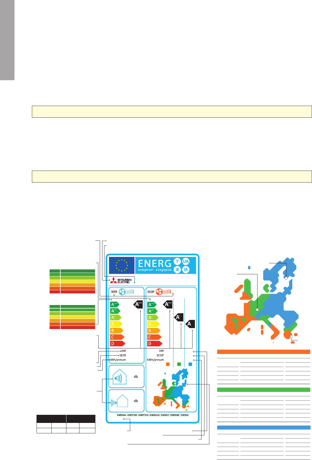
NEW ECODESIGN DIRECTIVE
Technical Terms with Respect to the SCOP
P design H:
Corresponds to a heating load of 100%.
The value depends on the selected bivalence point.
T design: Outside temperature which determines
the P design H point. The latter is determined from
the area conditions.
T bivalent: Corresponds to the lowest temperature
at which full heating performance can be achieved
with the heat pump (without additional heating).
This point can be freely selected within the pre-
scribed temperature ranges (T design - T bivalent).
■
New Energy Efficiency Label
■
SCOP Calculation
■
Climate Zones for Heating Mode
Nominal capacity in heating mode
SCOP value
Annual power consumption for heating
Time reference
Indication on label data
Energy efficiency classes from A+++ to D
SEER in cooling mode
Energy efficiency class
Energy efficiency class of the
unit in cooling and heating
mode of the unit model
In the heating mode, the indication
for the unit model is shown for
all three climate zones.
Annual power consumption for cooling
Nominal capacity in cooling mode
SEER value
A +++> 8,5
A ++ > 6,1
A +> 5,6
C > 4,1
D < 3,6
B> 4,6
> 5,1
A
Cooling capacity Cooling capacity
≤ 6 kW
> 6 kW ≤ 12 kW
I
ndoor unit
Outdoor unit Indoor unit Outdoor unit
60dB(A) 65dB(A) 60dB(A) 70dB(A)
Operating noise, indoors/outdoors
The sound power level is an
important sound energy parameter
for assessing a sound source.
Contrary to the sound pressure -
the sound power is independent
of the location of the source
and/or the receiver.
Maximally admissible values are:
Climate zones
For heating mode, the EU is divided into three climate zones for
calculation and classification purposes. This aims at calculating
the energy efficiency taking into consideration the actual regional
ambient temperatures.
Name of the unit/designation of model
Name or trademark of the manufacturer
Energy efficiency classes from A+++ to D
SCOP in heating mode
A +++> 5,1
A ++ > 4,6
A +> 4,0
A > 3,4
C > 2,8
D < 2,5
B> 3,1
SEER and SCOP
The SEER (Seasonal Energy Efficiency Ratio)
value indicates the seasonal energy efficiency
value in the cooling mode. The SCOP (Seasonal
Coefficient of Performance) value refers to the
seasonal efficiency in the heating mode.
Reference climate zones for calculating the SCOP
Since the climate conditions have a great influence on the operating
behaviour in the heat pump mode, three climate zones have
been stipulated for the EU: warm, moderate, cold. The measurement
points are homogenous at 12°C, 7°C, 2°C and –7°C.
Warm (Athens)
Temperature conditions
Partial
load
Outdoors Indoors
DB WB DB
–
100%
64%
29%
–
2°C
7°C
12°C
–
1°C
6°C
11°C
20°C
20°C
20°C
20°C
Cold (Helsinki)
Temperature conditions
Partial
load
61%
37%
24%
11%
Moderate (Strasbourg)
Temperature conditions
Partial
load
88%
54%
35%
15%
Outdoors Indoors
DB WB DB
–7°C
2°C
7°C
12°C
–8°C
1°C
6°C
11°C
20°C
20°C
20°C
20°C
Outdoors Indoors
DB WB DB
–7°C
2°C
7°C
12°C
–8°C
1°C
6°C
11°C
20°C
20°C
20°C
20°C
P design H
-10°C-7°C-2°C 16°C
Outside
temperature
Heating capacity at
nominal frequency
SCOP calculation in
the heat pump mode
If T bivalent is high
P design H = high
SCOP = low
T bivalent
Helsinki
Strasbourg
Athens
Strasbourg also
serves as basis for
calculating the SEER.
The Ecodesign Directive for Energy-related Products (ErP Directive) establishes a framework to set mandatory standards for ErPs sold in the
European Union (EU). The ErP directive introduces new energy-efficiency ratings across various product categories and affects how products such
as computers, vacuum cleaners, boilers and even windows are classified in terms of environmental performance.
Regulations that apply to air conditioning systems of rated capacity up to 12kW came into effect as of January 1, 2013. Based the use of future-
orientated technologies, Mitsubishi Electric is one step ahead of these changes, with our air conditioning systems already achieving compliance
with these new regulations.
WHAT IS THE ErP DIRECTIVE?
Air conditioning systems were previously assessed using the energy-efficiency rating (EER), which evaluated efficiency in cooling mode, and the
coefficient of performance (COP), which defined the efficiency, or the ratio of consumed and output power, in heating mode. Under this system,
assessments were not truly reflective of performance as they were based on a single measurement point, which led to manufacturers optimising
products accordingly in order to achieve higher efficiency ratings. SEER and SCOP address this problem by including seasonal variation in the
ratings via use of realistic measurement points. For cooling mode, measurements at outside temperatures of 20, 25, 30 and 35°C are incorporated
and weighted in accordance with climate data for Strasbourg, which is used as a single reference point for the whole EU. For instance, for
partial-load operation, which represents more than 90% of operation, there is a correspondingly high weighting for the efficiency classification. For
heating mode, a comprehensive temperature profile for the whole EU was not possible, so the EU has been divided into three climate zones,
north, central and south, and load profiles created. The same measurement points, at outside temperatures of 12, 7, 2 and –7°C, are used for all
three zones.
SEER/SCOP
SOUND PRESSURE LEVEL
Under regulation 2011/626/EU, supplementing directive 2010/30/EU, air conditioning systems are newly classified into energy-efficiency classes
on the basis of a new energy labelling system, which includes three new classes: A
+
, A
++
and A
+++
.
Revisions to the measurement points and calculations of the seasonal energy efficiency ratio (SEER) and seasonal coefficient of performance
(SCOP) has resulted in changes to how air conditioning systems are classified into energy-efficiency classes.
Specifically, for cooling mode, air conditioning systems must achieve at least class B. For heating mode, air conditioning systems must achieve at
least a SCOP value of 3.8.
NEW ENERGY LABEL AND MEASUREMENTS
Consumers will also receive more information on the noise
levels emitted by split-system air conditioners to help them
make their purchasing decision. Specifically, the sound power
level of indoor and outdoor units is to be indicated in decibels
as an objective parameter. Knowing the sound power makes
it possible to calculate sound emissions while considering
distance and radiation characteristics, which is beneficial
because it allows the noise levels of different air conditioning
systems to be compared regardless of the usage location and
how the sound pressure is measured. This is an improvement
on sound pressure values which are usually measured at an
approximate distance of 1m where all modern split-system air
conditioning systems tend to be very quiet at an average of
21 decibels.
■
Sound Pressure vs Sound Power Level
Sound pressure level dB(A)
The sound pressure level is a sound field parameter
which indicates the perceived operating noise of an
indoor unit within a certain distance.
Sound power level dB(A)
The sound power is an acoustic parameter which
describes the source strength of a sound generator
and is thus independent of the distance to the
receiver location.
10
XY,Z
III
XY,Z XY,Z XY,Z
X,YX,Y X,YX,Y
XY
ZY
ZY
XYZ/2012
XY XY XY
NEW ECODESIGN DIRECTIVE
Technical Terms with Respect to the SCOP
P design H:
Corresponds to a heating load of 100%.
The value depends on the selected bivalence point.
T design: Outside temperature which determines
the P design H point. The latter is determined from
the area conditions.
T bivalent: Corresponds to the lowest temperature
at which full heating performance can be achieved
with the heat pump (without additional heating).
This point can be freely selected within the pre-
scribed temperature ranges (T design - T bivalent).
■
New Energy Efficiency Label
■
SCOP Calculation
■
Climate Zones for Heating Mode
Nominal capacity in heating mode
SCOP value
Annual power consumption for heating
Time reference
Indication on label data
Energy efficiency classes from A+++ to D
SEER in cooling mode
Energy efficiency class
Energy efficiency class of the
unit in cooling and heating
mode of the unit model
In the heating mode, the indication
for the unit model is shown for
all three climate zones.
Annual power consumption for cooling
Nominal capacity in cooling mode
SEER value
A +++> 8,5
A ++ > 6,1
A +> 5,6
C > 4,1
D < 3,6
B> 4,6
> 5,1
A
Cooling capacity Cooling capacity
≤ 6 kW
> 6 kW ≤ 12 kW
I
ndoor unit
Outdoor unit Indoor unit Outdoor unit
60dB(A) 65dB(A) 60dB(A) 70dB(A)
Operating noise, indoors/outdoors
The sound power level is an
important sound energy parameter
for assessing a sound source.
Contrary to the sound pressure -
the sound power is independent
of the location of the source
and/or the receiver.
Maximally admissible values are:
Climate zones
For heating mode, the EU is divided into three climate zones for
calculation and classification purposes. This aims at calculating
the energy efficiency taking into consideration the actual regional
ambient temperatures.
Name of the unit/designation of model
Name or trademark of the manufacturer
Energy efficiency classes from A+++ to D
SCOP in heating mode
A +++> 5,1
A ++ > 4,6
A +> 4,0
A > 3,4
C > 2,8
D < 2,5
B> 3,1
SEER and SCOP
The SEER (Seasonal Energy Efficiency Ratio)
value indicates the seasonal energy efficiency
value in the cooling mode. The SCOP (Seasonal
Coefficient of Performance) value refers to the
seasonal efficiency in the heating mode.
Reference climate zones for calculating the SCOP
Since the climate conditions have a great influence on the operating
behaviour in the heat pump mode, three climate zones have
been stipulated for the EU: warm, moderate, cold. The measurement
points are homogenous at 12°C, 7°C, 2°C and –7°C.
Warm (Athens)
Temperature conditions
Partial
load
Outdoors Indoors
DB WB DB
–
100%
64%
29%
–
2°C
7°C
12°C
–
1°C
6°C
11°C
20°C
20°C
20°C
20°C
Cold (Helsinki)
Temperature conditions
Partial
load
61%
37%
24%
11%
Moderate (Strasbourg)
Temperature conditions
Partial
load
88%
54%
35%
15%
Outdoors Indoors
DB WB DB
–7°C
2°C
7°C
12°C
–8°C
1°C
6°C
11°C
20°C
20°C
20°C
20°C
Outdoors Indoors
DB WB DB
–7°C
2°C
7°C
12°C
–8°C
1°C
6°C
11°C
20°C
20°C
20°C
20°C
P design H
-10°C-7°C-2°C 16°C
Outside
temperature
Heating capacity at
nominal frequency
SCOP calculation in
the heat pump mode
If T bivalent is high
P design H = high
SCOP = low
T bivalent
Helsinki
Strasbourg
Athens
Strasbourg also
serves as basis for
calculating the SEER.
The Ecodesign Directive for Energy-related Products (ErP Directive) establishes a framework to set mandatory standards for ErPs sold in the
European Union (EU). The ErP directive introduces new energy-efficiency ratings across various product categories and affects how products such
as computers, vacuum cleaners, boilers and even windows are classified in terms of environmental performance.
Regulations that apply to air conditioning systems of rated capacity up to 12kW came into effect as of January 1, 2013. Based the use of future-
orientated technologies, Mitsubishi Electric is one step ahead of these changes, with our air conditioning systems already achieving compliance
with these new regulations.
WHAT IS THE ErP DIRECTIVE?
Air conditioning systems were previously assessed using the energy-efficiency rating (EER), which evaluated efficiency in cooling mode, and the
coefficient of performance (COP), which defined the efficiency, or the ratio of consumed and output power, in heating mode. Under this system,
assessments were not truly reflective of performance as they were based on a single measurement point, which led to manufacturers optimising
products accordingly in order to achieve higher efficiency ratings. SEER and SCOP address this problem by including seasonal variation in the
ratings via use of realistic measurement points. For cooling mode, measurements at outside temperatures of 20, 25, 30 and 35°C are incorporated
and weighted in accordance with climate data for Strasbourg, which is used as a single reference point for the whole EU. For instance, for
partial-load operation, which represents more than 90% of operation, there is a correspondingly high weighting for the efficiency classification. For
heating mode, a comprehensive temperature profile for the whole EU was not possible, so the EU has been divided into three climate zones,
north, central and south, and load profiles created. The same measurement points, at outside temperatures of 12, 7, 2 and –7°C, are used for all
three zones.
SEER/SCOP
SOUND PRESSURE LEVEL
Under regulation 2011/626/EU, supplementing directive 2010/30/EU, air conditioning systems are newly classified into energy-efficiency classes
on the basis of a new energy labelling system, which includes three new classes: A
+
, A
++
and A
+++
.
Revisions to the measurement points and calculations of the seasonal energy efficiency ratio (SEER) and seasonal coefficient of performance
(SCOP) has resulted in changes to how air conditioning systems are classified into energy-efficiency classes.
Specifically, for cooling mode, air conditioning systems must achieve at least class B. For heating mode, air conditioning systems must achieve at
least a SCOP value of 3.8.
NEW ENERGY LABEL AND MEASUREMENTS
Consumers will also receive more information on the noise
levels emitted by split-system air conditioners to help them
make their purchasing decision. Specifically, the sound power
level of indoor and outdoor units is to be indicated in decibels
as an objective parameter. Knowing the sound power makes
it possible to calculate sound emissions while considering
distance and radiation characteristics, which is beneficial
because it allows the noise levels of different air conditioning
systems to be compared regardless of the usage location and
how the sound pressure is measured. This is an improvement
on sound pressure values which are usually measured at an
approximate distance of 1m where all modern split-system air
conditioning systems tend to be very quiet at an average of
21 decibels.
■
Sound Pressure vs Sound Power Level
Sound pressure level dB(A)
The sound pressure level is a sound field parameter
which indicates the perceived operating noise of an
indoor unit within a certain distance.
Sound power level dB(A)
The sound power is an acoustic parameter which
describes the source strength of a sound generator
and is thus independent of the distance to the
receiver location.
11
INVERTER TECHNOLOGIES
Mitsubishi Electric inverters ensure superior performance including the optimum control of operation frequency. As a result,
optimum power is applied in all heating/cooling ranges and maximum comfort is achieved while consuming minimal energy.
Fast, comfortable operation and amazingly low running cost — That’s the Mitsubishi Electric promise.
Inverters electronically control the electrical voltage, current and frequency of electrical devices such as the compressor motor in an air conditioner.
They receive information from sensors monitoring operating conditions, and adjust the revolution speed of the compressor, which directly
regulates air conditioner output. Optimum control of operation frequency results in eliminating the consumption of excessive electricity and
providing the most comfortable room environment.
Quick & Powerful
Increasing the compressor motor speed by controlling the operation
frequency ensures powerful output at start-up, brings the room
temperature to the comfort zone faster than units not equipped with
an inverter. Hot rooms are cooled, and cold rooms are heated faster
and more efficiently.
Room Temperature Maintained
The compressor motor operating frequency and the change of room
temperature are monitored to calculate the most efficient waveform
to maintain the room temperature in the comfort zone. This elimi-
nates the large temperature swings common with non-inverter sys-
tems, and guarantees a pleasant, comfortable environment.
Vector-Wave Eco Inverter
This inverter monitors the varying compressor motor frequency and
creates the most efficient waveform for the motor speed. As the
result, operating efficiency in all speed ranges is improved, less
power is used and annual electricity cost is reduced.
Inverter size has been reduced using insert-
molding, where the circuit pattern is molded into
the synthetic resin. To ensure quiet operation,
soft PWM control is used to prevent the metallic
whine associated with conventional inverters.
Sine-wave drive soft PWM
Smooth wave pattern
MORE ADVANTAGES WITH MITSUBISHI ELECTRIC
INVERTERS – HOW THEY WORK
Impressively low operating cost is a key advantage of inverter air conditioners. We’ve combined advanced inverter technologies with cutting-edge
electronics and mechanical technologies to achieve a synergistic effect that enables improvements in heating/cooling performance efficiency.
Better performance and lower energy consumption are the result.
ECONOMIC OPERATION
KEY TECHNOLOGIES
Simple comparison of air conditioner operation control with and without inverter.
TRUE COMFORT
■
Inverter Operation Image (cooling mode)
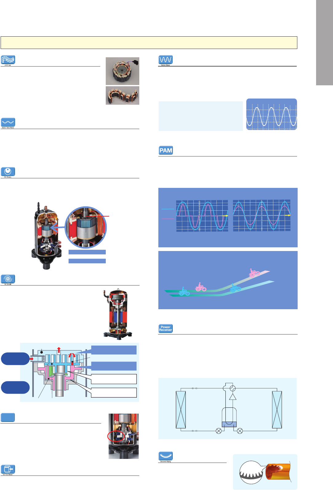
Grooved Piping
High-performance grooved piping
is used in heat exchangers to in-
crease the heat exchange area.
DC Fan Motor
A highly efficient DC motor drives the fan of the outdoor unit.
Efficiency is much higher than an equivalent AC motor.
Joint Lap DC Motor
Mitsubishi Electric has developed a unique motor,
called the “Poki-Poki Motor” in Japan, which is
manufactured using a joint lapping technique.
This innovative motor operates based on a high-
density, high-magnetic force, leading to extremely
high efficiency and reliability.
Grooved piping
Cross-sectional view
Pipe image
Magnetic Flux Vector Sine Wave Drive
This drive device is actually a microprocessor that converts the com-
pressor motor’s electrical current waveform from a conventional wave-
form to a sine wave (180°conductance) to achieve higher efficiency by
raising the motor winding utilisation ratio and reducing energy loss.
Reluctance DC Rotary Compressor
Powerful neodymium magnets are used in the rotor of the reluc-
tance DC motor. More efficient operation is realised by strong mag-
netic and reluctance torques produced by the magnets.
DC compressor
motor ( rotor )
Neodymium
magnets
Magnetic torque
+
Reluctance torque
PAM
Conventional
inverter
Without PAM control
■
Merits of PAM Control
With PAM control
Supply
voltage
Current
Time
T
ime
PAM adjusts the form of the current wave so that it b
ecomes close to that of the supply
voltage wave. High harmonics are reduced and 9
8% of the electricity is utilized.
PAM is a technology that controls the current waveform so that it
resembles the supply voltage wave, thereby reducing loss and real-
ising more efficient use of electricity. Using PAM control, 98% of the
input power supply is used effectively.
PAM
(Pulse Amplitude Modulation)
Power increased
Efficient voltage increase
realises increased power
Significant energy savings
Remarkable reduction in power
loss saves electricity
Limited power
Insufficient power
when needed
Limited energy savings
Electricity is wasted
LEV1
Power
receiver
Heat
exchanger
Heat
exchanger
Compressor
LEV2
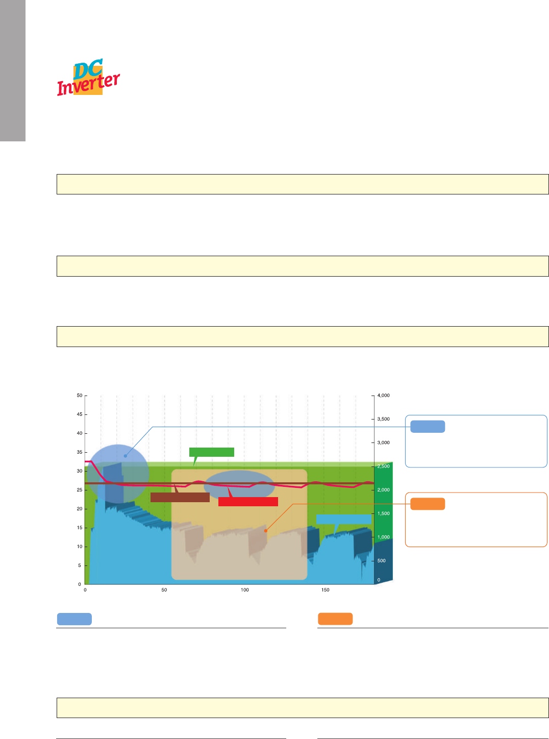
Power Receiver and Twin LEV Control
Mitsubishi Electric has developed a power receiver and twin linear
expansion valves (LEVs) circuit that optimise compressor perfor-
mance. This technology ensures optimum control in response to op-
erating waveform and outdoor temperature. Operating efficiency has
been enhanced by tailoring the system to the characteristics of R410A
refrigerant.
Temperature (°C)
Cooling capacity (W)
Operation time (min)
Rated capacity
Setting temperature
Indoor temperature
Measured capacity
Point 1
Point 1
When room temperature is higher than the
setting, capacity rises for the quickly adjust-
ing the temperature to the original setting.
When room temperature reaches the desired
setting, capacity eases in order to maintain
the set temperature level.
Point 2
Point 2
Highly Efficient DC Scroll Compressor
Higher efficiency has been achieved by adding a
frame compliance mechanism to the DC scroll
compressor. The mechanism allows movement
in the axial direction of the frame supporting the
cradle scroll, thereby greatly reducing leakage
and friction loss, and ensuring extremely high
efficiency at all speeds.
To fix internal parts in place, a “Heat Caulking
Fixing Method” is used, replacing the former arc
spot welding method. Distortion of internal parts
is reduced, realising higher efficiency.
Thrust gas power (minimum)
Cradle scrollFrame
Secondary back-pressure chamber
minimises thrust friction loss
Primary back-chamber minimises
leakage loss
Thrust friction loss (minimum)
Leakage loss (minimum)
Fixed scroll
Frame can
move in direction
of axis
Substantial
reduction in leakage
and friction loss
Our Rotary Compressor
Our rotary compressors use our original “Poki-Poki Motor” and
“Heat Caulking Fixing Method” to realise downsizing and higher
efficiency, and are designed to match various usage scenes in
residential to commercial applications. Additionally, development of
an innovative production method known as “Divisible Middle Plate”
realises further size/weight reductions and increased capacity while
also answering energy-efficiency needs.
Our Scroll Compressor
Our scroll compressors are equipped with an advanced frame
compliance mechanism that allows self-adjustment of the position
of the orbiting scroll according to pressure load and the accuracy of
the fixed scroll position. This minimises gas leakage in the scroll
compression chamber, maintains cooling capacity and reduces
power loss.
Heat Caulking Fixing Method
Heat Caulking
Fixing Method
12
INVERTER TECHNOLOGIES
Mitsubishi Electric inverters ensure superior performance including the optimum control of operation frequency. As a result,
optimum power is applied in all heating/cooling ranges and maximum comfort is achieved while consuming minimal energy.
Fast, comfortable operation and amazingly low running cost — That’s the Mitsubishi Electric promise.
Inverters electronically control the electrical voltage, current and frequency of electrical devices such as the compressor motor in an air conditioner.
They receive information from sensors monitoring operating conditions, and adjust the revolution speed of the compressor, which directly
regulates air conditioner output. Optimum control of operation frequency results in eliminating the consumption of excessive electricity and
providing the most comfortable room environment.
Quick & Powerful
Increasing the compressor motor speed by controlling the operation
frequency ensures powerful output at start-up, brings the room
temperature to the comfort zone faster than units not equipped with
an inverter. Hot rooms are cooled, and cold rooms are heated faster
and more efficiently.
Room Temperature Maintained
The compressor motor operating frequency and the change of room
temperature are monitored to calculate the most efficient waveform
to maintain the room temperature in the comfort zone. This elimi-
nates the large temperature swings common with non-inverter sys-
tems, and guarantees a pleasant, comfortable environment.
Vector-Wave Eco Inverter
This inverter monitors the varying compressor motor frequency and
creates the most efficient waveform for the motor speed. As the
result, operating efficiency in all speed ranges is improved, less
power is used and annual electricity cost is reduced.
Inverter size has been reduced using insert-
molding, where the circuit pattern is molded into
the synthetic resin. To ensure quiet operation,
soft PWM control is used to prevent the metallic
whine associated with conventional inverters.
Sine-wave drive soft PWM
Smooth wave pattern
MORE ADVANTAGES WITH MITSUBISHI ELECTRIC
INVERTERS – HOW THEY WORK
Impressively low operating cost is a key advantage of inverter air conditioners. We’ve combined advanced inverter technologies with cutting-edge
electronics and mechanical technologies to achieve a synergistic effect that enables improvements in heating/cooling performance efficiency.
Better performance and lower energy consumption are the result.
ECONOMIC OPERATION
KEY TECHNOLOGIES
Simple comparison of air conditioner operation control with and without inverter.
TRUE COMFORT
■
Inverter Operation Image (cooling mode)
Grooved Piping
High-performance grooved piping
is used in heat exchangers to in-
crease the heat exchange area.
DC Fan Motor
A highly efficient DC motor drives the fan of the outdoor unit.
Efficiency is much higher than an equivalent AC motor.
Joint Lap DC Motor
Mitsubishi Electric has developed a unique motor,
called the “Poki-Poki Motor” in Japan, which is
manufactured using a joint lapping technique.
This innovative motor operates based on a high-
density, high-magnetic force, leading to extremely
high efficiency and reliability.
Grooved piping
Cross-sectional view
Pipe image
Magnetic Flux Vector Sine Wave Drive
This drive device is actually a microprocessor that converts the com-
pressor motor’s electrical current waveform from a conventional wave-
form to a sine wave (180°conductance) to achieve higher efficiency by
raising the motor winding utilisation ratio and reducing energy loss.
Reluctance DC Rotary Compressor
Powerful neodymium magnets are used in the rotor of the reluc-
tance DC motor. More efficient operation is realised by strong mag-
netic and reluctance torques produced by the magnets.
DC compressor
motor ( rotor )
Neodymium
magnets
Magnetic torque
+
Reluctance torque
PAM
Conventional
inverter
Without PAM control
■
Merits of PAM Control
With PAM control
Supply
voltage
Current
Time
T
ime
PAM adjusts the form of the current wave so that it b
ecomes close to that of the supply
voltage wave. High harmonics are reduced and 98% of the electricity is utilized.
PAM is a technology that controls the current waveform so that it
resembles the supply voltage wave, thereby reducing loss and real-
ising more efficient use of electricity. Using PAM control, 98% of the
input power supply is used effectively.
PAM
(Pulse Amplitude Modulation)
Power increased
Efficient voltage increase
realises increased power
Significant energy savings
Remarkable reduction in power
loss saves electricity
Limited power
Insufficient power
when needed
Limited energy savings
Electricity is wasted
LEV1
Power
receiver
Heat
exchanger
Heat
exchanger
Compressor
LEV2
Power Receiver and Twin LEV Control
Mitsubishi Electric has developed a power receiver and twin linear
expansion valves (LEVs) circuit that optimise compressor perfor-
mance. This technology ensures optimum control in response to op-
erating waveform and outdoor temperature. Operating efficiency has
been enhanced by tailoring the system to the characteristics of R410A
refrigerant.
Temperature (°C)
Cooling capacity (W)
Operation time (min)
Rated capacity
Setting temperature
Indoor temperature
Measured capacity
Point 1
Point 1
When room temperature is higher than the
setting, capacity rises for the quickly adjust-
ing the temperature to the original setting.
When room temperature reaches the desired
setting, capacity eases in order to maintain
the set temperature level.
Point 2
Point 2
Highly Efficient DC Scroll Compressor
Higher efficiency has been achieved by adding a
frame compliance mechanism to the DC scroll
compressor. The mechanism allows movement
in the axial direction of the frame supporting the
cradle scroll, thereby greatly reducing leakage
and friction loss, and ensuring extremely high
efficiency at all speeds.
To fix internal parts in place, a “Heat Caulking
Fixing Method” is used, replacing the former arc
spot welding method. Distortion of internal parts
is reduced, realising higher efficiency.
Thrust gas power (minimum)
Cradle scrollFrame
Secondary back-pressure chamber
minimises thrust friction loss
Primary back-chamber minimises
leakage loss
Thrust friction loss (minimum)
Leakage loss (minimum)
Fixed scroll
Frame can
move in direction
of axis
Substantial
reduction in leakage
and friction loss
Our Rotary Compressor
Our rotary compressors use our original “Poki-Poki Motor” and
“Heat Caulking Fixing Method” to realise downsizing and higher
efficiency, and are designed to match various usage scenes in
residential to commercial applications. Additionally, development of
an innovative production method known as “Divisible Middle Plate”
realises further size/weight reductions and increased capacity while
also answering energy-efficiency needs.
Our Scroll Compressor
Our scroll compressors are equipped with an advanced frame
compliance mechanism that allows self-adjustment of the position
of the orbiting scroll according to pressure load and the accuracy of
the fixed scroll position. This minimises gas leakage in the scroll
compression chamber, maintains cooling capacity and reduces
power loss.
Heat Caulking Fixing Method
Heat Caulking
Fixing Method
13
FUNCTIONS
(
1
)
i-see Sensor
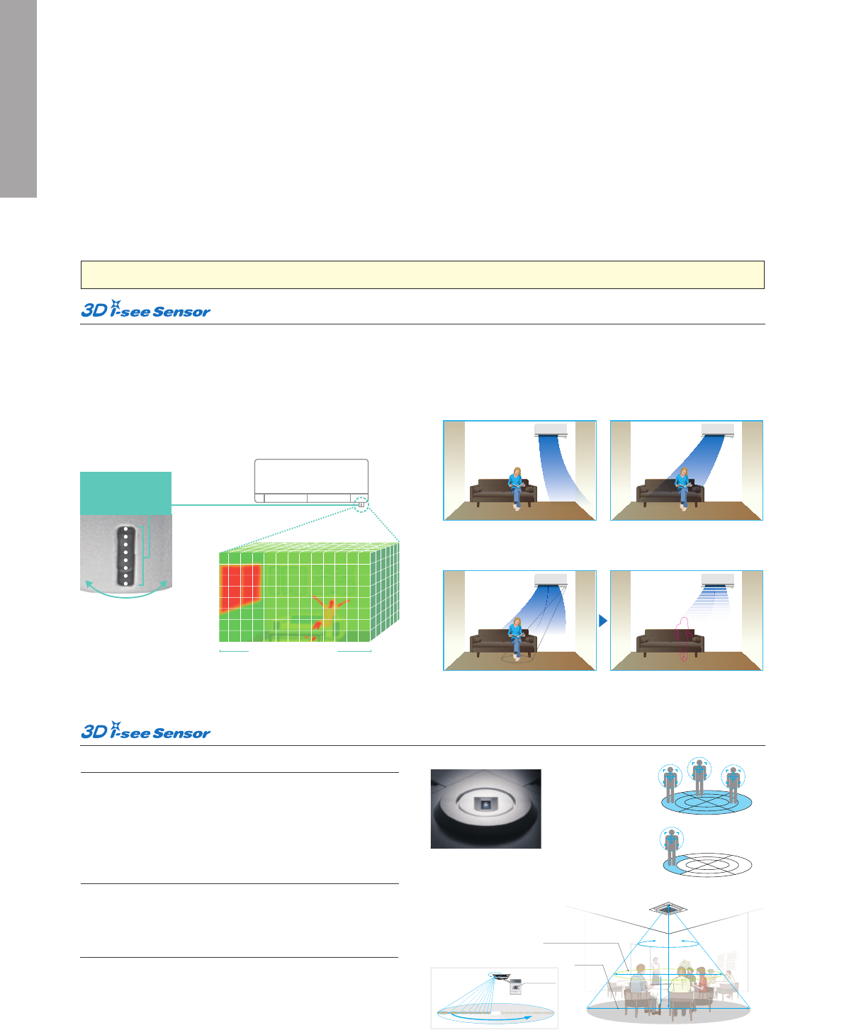
The FH Series is equipped with 3D i-see Sensor, an infrared-ray
sensor that measures the temperature at distant positions. While
moving to the left and right, eight vertically arranged sensor
elements analyze the room temperature in three dimensions. This
detailed analysis makes it possible to judge where people are
in the room, thus allowing creation of features such as “Indirect
airflow,” to avoid airflow hitting people directly, and “direct airflow”
to deliver airflow to where people are.
8 × 94 areas
(Image)
Divided into 94
Sensor with
eight elements
Sensor measures while
moving to the left to right
The indirect airflow setting can be used
when the flow of air feels too strong or
direct. For example, it can be used during
cooling to avert airflow and prevent body
temperature from becoming excessively
cooled.
Indirect Airflow
The sensors detect whether there are people in the room. When no-one is in the room,
the unit automatically switches to energy-saving mode.
The “3D i-see Sensor” detects people’s absence and the power consumption is automatically
reduced approximately 10% after 10 minutes and 20% after 60 minutes.
Absence Detection
This setting can be used to directly target
airflow at people such as for immediate
comfort when coming indoors on a hot
(cold) day.
Direct Airflow
Area Temperature Monitor
The “i-see Sensor” monitors the whole room in sections and directs
the airflow to areas of the room where the temperature does not
match the temperature setting. (When cooling the room, if the middle
of the room is detected to be hotter, more airflow is directed towards
it.) This eliminates unnecessary heating /cooling and contributes to
lower electricity costs.
Daytime
Warmer
area
Cooler
area
Nighttime
Cooling mode
for M SERIES
for S SERIES
Cooling Heating
Room occupancy energy save mode
*PAR-32MAA is required for each setting
1C°
power
savings
No occupancy energy save mode
No occupancy Auto-Off mode
2C°
power
savings
Auto-Off
Direct/Indirect settings*
The horizontal airflow spreads across the ceiling.
When set to “Indirect Airflow” uncomfortable
drafty-feeling is eliminated completely!
Detects people’s position
Once a person is detected, the angle of the vane is automatically
adjusted. Each vane can be indenpendently set to “Direct Airflow”
or “Indirect Airflow” according to taste.
Detects number of people
The 3D i-see Sensor detects the number of people in the room and
adjusts the power accordingly. This makes automatic power-saving
operation possible in places where the number of people changes
frequently. Additionally, when the area is continuously unoccupied,
the system switches to a more enhanced power-saving mode. De-
pending on the setting, it can also stop the operation.
Highly accurate people detection
A total of eight sensors rotate a full 360° in 3-minute intervals. In
addition to detecting human body temperature, our original algo-
rithm also detects people’s positions and the number of people.
Seasonal airflow*
When cooling
Saves energy while keeping a comfort-
able effective temperature by automati-
cally switching between ventilation and
cooling. When a pre-set temperature
is reached, the air conditioning unit
switches to swing fan operation to
maintain the effective temperature.
This clever function contributes to
keeping a comfortable coolness.
When heating
The air conditioning unit automatically
switches between circulator and heating.
Wasted heat that accumulates near the
ceiling is reused via circulation. When a
pre-set temperature is reached the air con-
ditioner switches from heating to circulator
and blows air in the horizontal direction. It
pushes down the warm air that has gath-
ered near the ceiling to people’s height,
thereby providing smart heating.
Detects people’s
position
Detects number
of people
Detects number of people
Detects people’s position
1234 5678
1 2 3 4 5
6 7
8
8 sensors
360°
Detection
360°
Detection
7.2m
2.7m
12m
1.1m
Detects floor
temperature
Detects position
and number of people
Floor surface
*In case of a 2.7m ceiling
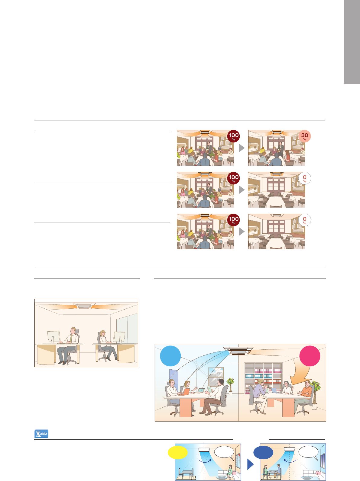
The 3D i-see Sensor detects the number of people in the room. It
then calculates the occupancy rate based on the maximum number
of people in the room up to that point in time in order to save air-
conditioning power. When the occupancy rate is approximately
30%, air-conditioning power equivalent to 1°C during both cooling
and heating operation is saved. The temperature is controlled ac-
cording to the number of people.
When 3D i-see Sensor detects that no one is the room, the system
is switched to a pre-set power-saving mode. If the room remains un-
occupied for more than 60min, air-conditioning power equivalent to
2°C during both cooling and heating operation is saved. This contrib-
utes to preventing waste in terms of heating and cooling.
When the room remains unoccupied for a pre-set period of time, the
air conditioner turns off automatically, thereby providing even
greater power savings. The time until operation is stopped can be
set in intervals of 10min, ranging from 60 to 180 min.
No occupancy Auto-OFF mode
No occupancy energy-saving mode
Room occupancy energy-saving mode
*PAR-32MAA is required for each setting.
*PAR-32MAA is required for each setting.
14
FUNCTIONS
(
1
)
i-see Sensor
The FH Series is equipped with 3D i-see Sensor, an infrared-ray
sensor that measures the temperature at distant positions. While
moving to the left and right, eight vertically arranged sensor
elements analyze the room temperature in three dimensions. This
detailed analysis makes it possible to judge where people are
in the room, thus allowing creation of features such as “Indirect
airflow,” to avoid airflow hitting people directly, and “direct airflow”
to deliver airflow to where people are.
8 × 94 areas
(Image)
Divided into 94
Sensor with
eight elements
Sensor measures while
moving to the left to right
The indirect airflow setting can be used
when the flow of air feels too strong or
direct. For example, it can be used during
cooling to avert airflow and prevent body
temperature from becoming excessively
cooled.
Indirect Airflow
The sensors detect whether there are people in the room. When no-one is in the room,
the unit automatically switches to energy-saving mode.
The “3D i-see Sensor” detects people’s absence and the power consumption is automatically
reduced approximately 10% after 10 minutes and 20% after 60 minutes.
Absence Detection
This setting can be used to directly target
airflow at people such as for immediate
comfort when coming indoors on a hot
(cold) day.
Direct Airflow
Area Temperature Monitor
The “i-see Sensor” monitors the whole room in sections and directs
the airflow to areas of the room where the temperature does not
match the temperature setting. (When cooling the room, if the middle
of the room is detected to be hotter, more airflow is directed towards
it.) This eliminates unnecessary heating /cooling and contributes to
lower electricity costs.
Daytime
Warmer
area
Cooler
area
Nighttime
Cooling mode
for M SERIES
for S SERIES
Cooling Heating
Room occupancy energy save mode
*PAR-32MAA is required for each setting
1C°
power
savings
No occupancy energy save mode
No occupancy Auto-Off mode
2C°
power
savings
Auto-Off
Direct/Indirect settings*
The horizontal airflow spreads across the ceiling.
When set to “Indirect Airflow” uncomfortable
drafty-feeling is eliminated completely!
Detects people’s position
Once a person is detected, the angle of the vane is automatically
adjusted. Each vane can be indenpendently set to “Direct Airflow”
or “Indirect Airflow” according to taste.
Detects number of people
The 3D i-see Sensor detects the number of people in the room and
adjusts the power accordingly. This makes automatic power-saving
operation possible in places where the number of people changes
frequently. Additionally, when the area is continuously unoccupied,
the system switches to a more enhanced power-saving mode. De-
pending on the setting, it can also stop the operation.
Highly accurate people detection
A total of eight sensors rotate a full 360° in 3-minute intervals. In
addition to detecting human body temperature, our original algo-
rithm also detects people’s positions and the number of people.
Seasonal airflow*
When cooling
Saves energy while keeping a comfort-
able effective temperature by automati-
cally switching between ventilation and
cooling. When a pre-set temperature
is reached, the air conditioning unit
switches to swing fan operation to
maintain the effective temperature.
This clever function contributes to
keeping a comfortable coolness.
When heating
The air conditioning unit automatically
switches between circulator and heating.
Wasted heat that accumulates near the
ceiling is reused via circulation. When a
pre-set temperature is reached the air con-
ditioner switches from heating to circulator
and blows air in the horizontal direction. It
pushes down the warm air that has gath-
ered near the ceiling to people’s height,
thereby providing smart heating.
Detects people’s
position
Detects number
of people
Detects number of people
Detects people’s position
1234 5678
1 2 3 4 5
6 7
8
8 sensors
360°
Detection
360°
Detection
7.2m
2.7m
12m
1.1m
Detects floor
temperature
Detects position
and number of people
Floor surface
*In case of a 2.7m ceiling
The 3D i-see Sensor detects the number of people in the room. It
then calculates the occupancy rate based on the maximum number
of people in the room up to that point in time in order to save air-
conditioning power. When the occupancy rate is approximately
30%, air-conditioning power equivalent to 1°C during both cooling
and heating operation is saved. The temperature is controlled ac-
cording to the number of people.
When 3D i-see Sensor detects that no one is the room, the system
is switched to a pre-set power-saving mode. If the room remains un-
occupied for more than 60min, air-conditioning power equivalent to
2°C during both cooling and heating operation is saved. This contrib-
utes to preventing waste in terms of heating and cooling.
When the room remains unoccupied for a pre-set period of time, the
air conditioner turns off automatically, thereby providing even
greater power savings. The time until operation is stopped can be
set in intervals of 10min, ranging from 60 to 180 min.
No occupancy Auto-OFF mode
No occupancy energy-saving mode
Room occupancy energy-saving mode
*PAR-32MAA is required for each setting.
*PAR-32MAA is required for each setting.
15
Plasma Quad
Plasma Quad attacks bacteria and viruses from inside the unit using
a strong curtain-like electrical field and discharge of electric current
across the whole inlet-air opening of the unit.
AIR QUALITY
AIR DISTRIBUTION
This high-performance filter has a much finer mesh compared to stan-
dard filters, and is capable of capturing minute particulates floating in
the air that were not previously caught.
High-efficiency Filter
The filter is charged with static electricity, enabling it to attract and
capture dust particulates that regular filters don’t.
Air Cleaning Filter
Catechin is a bioflavonoid by-product of green tea with both antiviral
and antioxidant qualities. It also has an excellent deodourising effect,
which is why Mitsubishi Electric uses the compound in its air condi-
tioner filters. In addition to improving air quality, it prevents the spread-
ing of bacteria and viruses throughout the room. Easily removed for
cleaning and maintenance, when the filter is washed regularly the de-
odourising action is rated to last more than 10 years.
Catechin Filter
Indoor air quality is enhanced by the direct intake of fresh exterior air.
Fresh-air Intake
The anti-allergy enzyme filter works to trap allergens such as molds
and bacteria and decompose them using enzymes retained in the
filter.
Anti-allergy Enzyme Filter
The air outlet vane swings up and down so that the airflow is spread
evenly throughout the room.
Horizontal Vane
The air outlet fin swings from side to side so that the airflow reaches
every part of the room.
Vertical Vane
A special process for the entrapment surface improves the filtering
effect, making the maintenance cycle longer than that of units
equipped with conventional filters.
Long-life Filter
Air conditioner operating time is monitored, and the user is notified
when filter maintenance is necessary.
Filter Check Signal
This function features both the Air Cleaning Filter and Anti-allergy
Enzyme Filter.
Electrostatic Anti-allergy Enzyme Filter
Double vane separates the airflow in the different directions to
deliver airflow not only across a wide area of the room, but also
simultaneously to two people in different locations.
Double Vane
In the case of rooms with high ceilings, the outlet-air volume can be
increased to ensure that air is circulated all the way to the floor.
High Ceiling Mode
If the room has a low ceiling, the airflow volume can be reduced for
less draft.
Low Ceiling Mode
The airflow speed mode adjusts the fan speed of the indoor unit
automatically according to the present room conditions.
Auto Fan Speed Mode
The filter has a large capture area and incorporates nanometre-sized
platinum-ceramic particles that work to kill bacteria and deodourise
the circulating air.
Nano Platinum Filter
The oil mist filter prevents oil mist from penetrating into the inner part
of the air conditioner.
Oil Mist Filter
Electrostatic
Anti-allergy
Nano
Platinum
Double
Vane
Pure White
Pure white is adopted for the unit colour; white expressing the
essence of cleanliness and easily matching virtually all interior décor.
Auto Vane
The vane closes automatically when the air conditioner is not
running, concealing the air outlet and creating a flat surface that is
aesthetically appealing.
ATTRACTIVE
Econo Cool Energy-Saving Feature
“Econo Cool” is an intelligent temperature control feature that adjusts
the amount of air directed towards the body based on the air-outlet
temperature. The setting temperature can be raised by as much as
2°C without any loss in comfort, thereby realising a 20% gain in
energy efficiency.
(Function only available during manual cooling operation.)
Econo Cool Mode
A comfortable room environment is maintained even when setting the
temperature 2°C higher than the conventional cooling mode.
Conventional Econo Cool
Ambient temperature 35°C 35°C
Set temperature 25°C 27°C
30°C 29.3°C
Econo Cool on Conventional cooling mode
14 16 18 20 22 24 26 28
Perceived temperature
Temperature distribution (°C)
✽PUHZ outdoor only
SW7-1
ON
SW2
OFF
ON
ON
OFF
SW3
OFF
OFF
ON
ON
Energy consumption
100%
75%
50%
0% (Stop)
Demand Function (Onsite Adjustment)
The demand function can be activated when the unit is equipped
with a commercially available timer or an On/Off switch is added to
the CNDM connector (option) on the control board of the outdoor
unit. Energy consumption can be reduced up to 100% of the normal
consumption according to the signal input from outside.
[
Example: Power Inverter Series
]
Limit energy consumption by changing the settings of SW7-1, SW2
and SW3 on the control board of the outdoor unit. The following
settings are possible.
ENERGY-SAVING
16
Plasma Quad
Plasma Quad attacks bacteria and viruses from inside the unit using
a strong curtain-like electrical field and discharge of electric current
across the whole inlet-air opening of the unit.
AIR QUALITY
AIR DISTRIBUTION
This high-performance filter has a much finer mesh compared to stan-
dard filters, and is capable of capturing minute particulates floating in
the air that were not previously caught.
High-efficiency Filter
The filter is charged with static electricity, enabling it to attract and
capture dust particulates that regular filters don’t.
Air Cleaning Filter
Catechin is a bioflavonoid by-product of green tea with both antiviral
and antioxidant qualities. It also has an excellent deodourising effect,
which is why Mitsubishi Electric uses the compound in its air condi-
tioner filters. In addition to improving air quality, it prevents the spread-
ing of bacteria and viruses throughout the room. Easily removed for
cleaning and maintenance, when the filter is washed regularly the de-
odourising action is rated to last more than 10 years.
Catechin Filter
Indoor air quality is enhanced by the direct intake of fresh exterior air.
Fresh-air Intake
The anti-allergy enzyme filter works to trap allergens such as molds
and bacteria and decompose them using enzymes retained in the
filter.
Anti-allergy Enzyme Filter
The air outlet vane swings up and down so that the airflow is spread
evenly throughout the room.
Horizontal Vane
The air outlet fin swings from side to side so that the airflow reaches
every part of the room.
Vertical Vane
A special process for the entrapment surface improves the filtering
effect, making the maintenance cycle longer than that of units
equipped with conventional filters.
Long-life Filter
Air conditioner operating time is monitored, and the user is notified
when filter maintenance is necessary.
Filter Check Signal
This function features both the Air Cleaning Filter and Anti-allergy
Enzyme Filter.
Electrostatic Anti-allergy Enzyme Filter
Double vane separates the airflow in the different directions to
deliver airflow not only across a wide area of the room, but also
simultaneously to two people in different locations.
Double Vane
In the case of rooms with high ceilings, the outlet-air volume can be
increased to ensure that air is circulated all the way to the floor.
High Ceiling Mode
If the room has a low ceiling, the airflow volume can be reduced for
less draft.
Low Ceiling Mode
The airflow speed mode adjusts the fan speed of the indoor unit
automatically according to the present room conditions.
Auto Fan Speed Mode
The filter has a large capture area and incorporates nanometre-sized
platinum-ceramic particles that work to kill bacteria and deodourise
the circulating air.
Nano Platinum Filter
The oil mist filter prevents oil mist from penetrating into the inner part
of the air conditioner.
Oil Mist Filter
Electrostatic
Anti-allergy
Nano
Platinum
Double
Vane
Pure White
Pure white is adopted for the unit colour; white expressing the
essence of cleanliness and easily matching virtually all interior décor.
Auto Vane
The vane closes automatically when the air conditioner is not
running, concealing the air outlet and creating a flat surface that is
aesthetically appealing.
ATTRACTIVE
Econo Cool Energy-Saving Feature
“Econo Cool” is an intelligent temperature control feature that adjusts
the amount of air directed towards the body based on the air-outlet
temperature. The setting temperature can be raised by as much as
2°C without any loss in comfort, thereby realising a 20% gain in
energy efficiency.
(Function only available during manual cooling operation.)
Econo Cool Mode
A comfortable room environment is maintained even when setting the
temperature 2°C higher than the conventional cooling mode.
Conventional Econo Cool
Ambient temperature 35°C 35°C
Set temperature 25°C 27°C
30°C 29.3°C
Econo Cool on Conventional cooling mode
14 16 18 20 22 24 26 28
Perceived temperature
Temperature distribution (°C)
✽PUHZ outdoor only
SW7-1
ON
SW2
OFF
ON
ON
OFF
SW3
OFF
OFF
ON
ON
Energy consumption
100%
75%
50%
0% (Stop)
Demand Function (Onsite Adjustment)
The demand function can be activated when the unit is equipped
with a commercially available timer or an On/Off switch is added to
the CNDM connector (option) on the control board of the outdoor
unit. Energy consumption can be reduced up to 100% of the normal
consumption according to the signal input from outside.
[
Example: Power Inverter Series
]
Limit energy consumption by changing the settings of SW7-1, SW2
and SW3 on the control board of the outdoor unit. The following
settings are possible.
ENERGY-SAVING
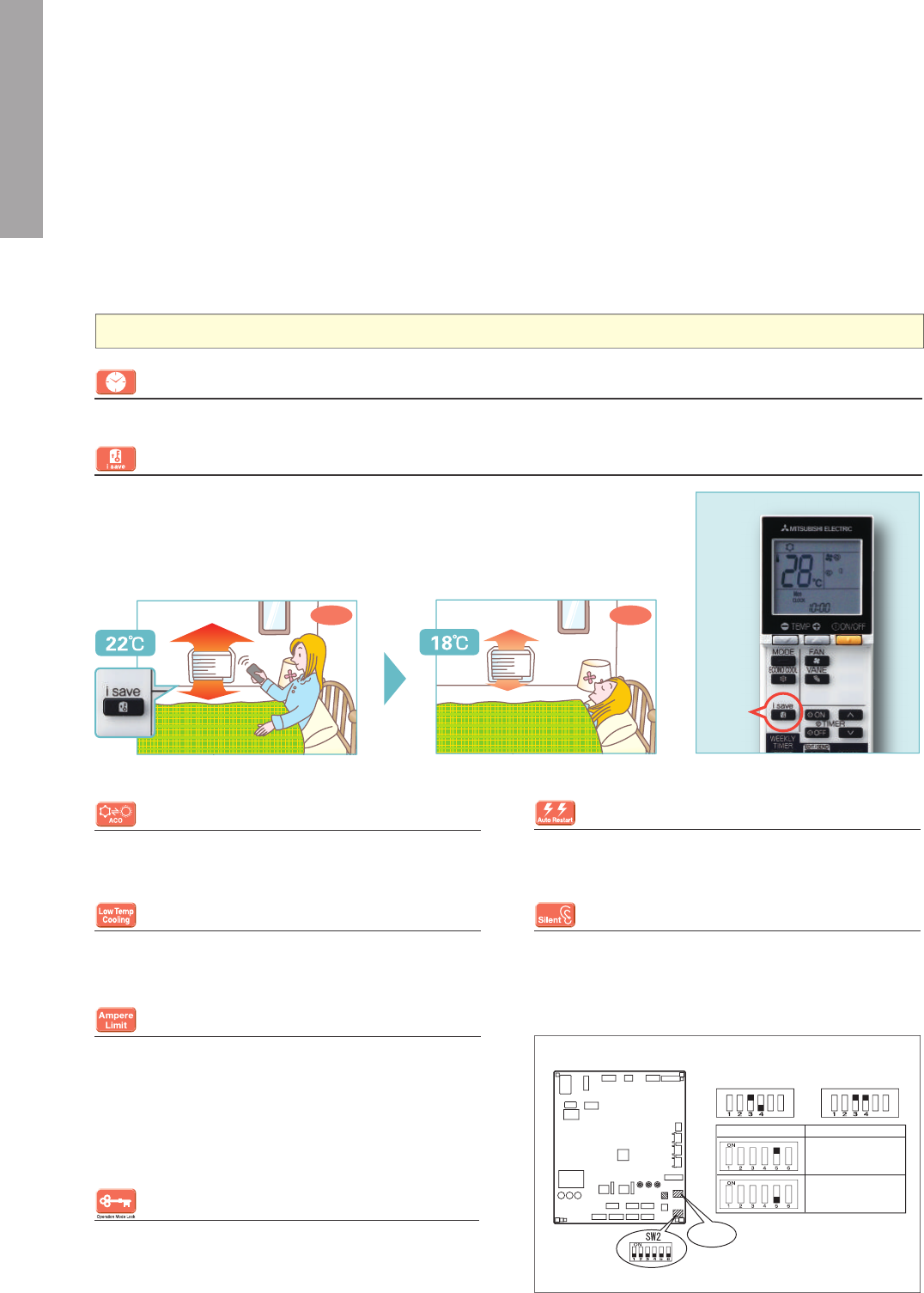
17
FUNCTIONS
(
2
)
“i save” Mode
“i save” is a simplified setting function that recalls the preferred (preset) temperature by pressing
a single button on the remote controller. Press the same button twice in repetition to immediately
return to the previous temperature setting.
Using this function contributes to comfortable waste-free operation, realising the most suitable air
conditioning settings and saving on power consumption when, for example, leaving the room or
going to bed.
Auto Restart
Especially useful at the time of power outages, the unit turns back on
automatically when power is restored.
Auto Changeover
The air conditioner automatically switches between heating and cool-
ing modes to maintain the desired temperature.
On/Off Operation Timer
Use the remote controller to set the times of turning the air conditioner On/Off.
Operation Lock
To accommodate specific use applications, cooling or heating
operation can be specified when setting the control board of the
outdoor unit. A convenient option when a system needs to be
configured for exclusive cooling or heating service.
i save
CONVENIENCE
SYSTEM CONTROL
COMPO
(Simultaneous Multi-unit Operation)
Multiple indoor units can be connected to a single outdoor unit.
(Depending on the unit combination, connection of up to four units is
possible; however, all indoor units must operate at the same settings.)
System Group Control
The same remote controller is capable of controlling the operational
status of up to 16 refrigerant systems.
MXZ Connection
Connection to the MXZ multi-split outdoor unit is possible.
Wi-Fi Interface
Interface enabling users to control air conditioners and check operat-
ing status via devices such as personal computers, tablets and smart-
phones.
Wi-Fi
Interface
M-NET Connection
Units can be connected to MELANS system controllers (M-NET
controllers) such as the AG-150A.
Ampere Limit Adjustment
Dip switch settings can be used to adjust the maximum electrical
current for operation. This function is highly recommended for
managing energy costs.
*Maximum capacity is lowered with the use of this function.
■
Dip Switch Setting
(Board for MXZ-5E102)
Low-noise Operation (Outdoor Unit)
System operation can be adjusted to prioritise less noise from the
outdoor unit over air conditioning performance.
Low-temperature Cooling
Intelligent fan speed control in the outdoor unit ensures optimum
performance even when the outside temperature is low.
Photo of MFZ Series remote controller
•
Start by pushing the “SET” button and follow the instructions to set the desired patterns.
Once all of the desired patterns are input, point the top end of the remote controller at the
indoor unit and push the “SET” button one more time. (Push the “SET” button only after in-
putting all of the desired patterns into the remote controller memory. Pushing the “CANCEL”
button will end the set-up process without sending the operation patterns to the indoor unit).
•
It takes a few seconds to transmit the Weekly Timer operation patterns to the indoor unit.
Please continue to point the remote controller at the indoor unit until all data has been sent.
■
Easy set-up using dedicated buttons
Ready to set
Complete
Select ON/OFF Select the time
Set the temperature
Select the day Select the period
How to set
the Weekly
Timer
PUSH PUSH
PUSHPUSHPUSH
PUSH
PUSH
Pattern Settings: Input up to four settings for each day
Settings:
•
Start/Stop operation
•
Temperature setting
✽
The operation mode cannot be set.
■ Example Operation Pattern (Winter/Heating mode)
Mon. Tues. Wed. Thurs. Fri. Sat. Sun.
ON 20°CON 20°CON 20°CON 20°C ON 20°C ON 20°CON 20°C
Automatically changes to high-power operation at wake-up time
Automatically lowers temperature at bedtime for energy-saving operation at night
ON 18°CON 18°CON 18°CON 18°C ON 18°C ON 18°CON 18°C
Settings
Built-in Weekly Timer Function
Easily set desired temperatures and operation ON/OFF times to match lifestyle patterns. Reduce wasted energy consumption by usi ng the timer
to prevent forgetting to turn off the unit and eliminate temperature setting adjustments.
PAR-32MAA/PAC-YT52CRA
Units are compatible for use with the PAR-32MAA or PAC-YT52CRA
remote controller,
which has a variety of management functions.
(during sleeping hours)
The remote controller is
equipped with buttons that
are used exclusively for
setting the Weekly Timer.
Setting operation patterns
is easy and quick.
Automatically turned off during work hours
Midday is warmer,
so the temperature is set lower
OFFOFFOFF OFF OFFON 18°CON 18°C
Automatically turns on, synchronized with arrival at home
Automatically raises temperature setting to
match time when outside-air temperature is low
ON 22°CON 22°CON 22°CON 22°C ON 22°C ON 22°CON 22°C
Heating Heating
✽ Temperature can be preset to 10°C when heating in the “i-save” mode.
Outdoor control P.C. board
SW1
ON
5
6
SW1
ON
5
6
SW1
Cool/Dry Heat
SW2
MXZ-4E83VAHZ
21 A
Default setting
26 A
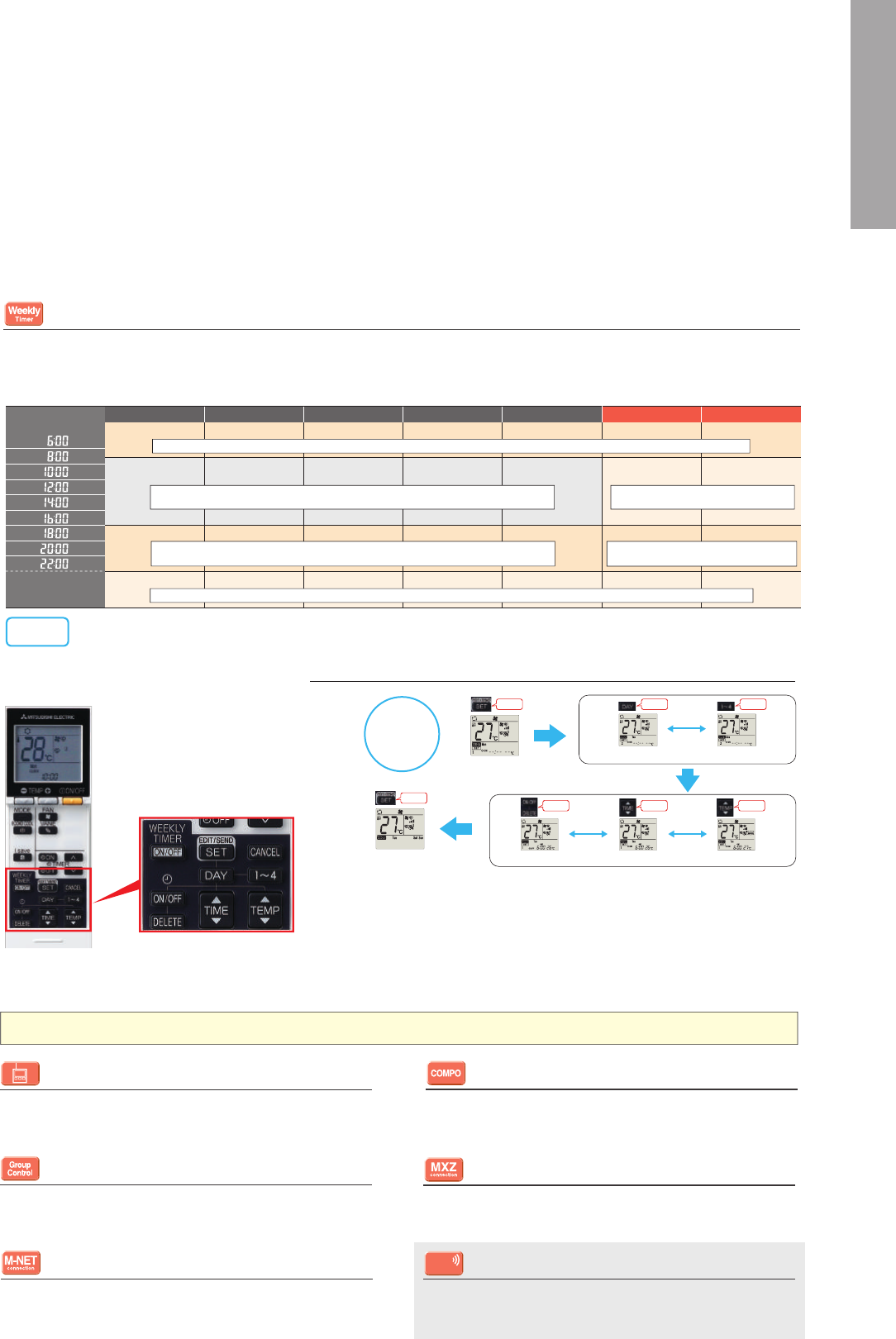
18
FUNCTIONS
(
2
)
“i save” Mode
“i save” is a simplified setting function that recalls the preferred (preset) temperature by pressing
a single button on the remote controller. Press the same button twice in repetition to immediately
return to the previous temperature setting.
Using this function contributes to comfortable waste-free operation, realising the most suitable air
conditioning settings and saving on power consumption when, for example, leaving the room or
going to bed.
Auto Restart
Especially useful at the time of power outages, the unit turns back on
automatically when power is restored.
Auto Changeover
The air conditioner automatically switches between heating and cool-
ing modes to maintain the desired temperature.
On/Off Operation Timer
Use the remote controller to set the times of turning the air conditioner On/Off.
Operation Lock
To accommodate specific use applications, cooling or heating
operation can be specified when setting the control board of the
outdoor unit. A convenient option when a system needs to be
configured for exclusive cooling or heating service.
i save
CONVENIENCE
SYSTEM CONTROL
COMPO
(Simultaneous Multi-unit Operation)
Multiple indoor units can be connected to a single outdoor unit.
(Depending on the unit combination, connection of up to four units is
possible; however, all indoor units must operate at the same settings.)
System Group Control
The same remote controller is capable of controlling the operational
status of up to 16 refrigerant systems.
MXZ Connection
Connection to the MXZ multi-split outdoor unit is possible.
Wi-Fi Interface
Interface enabling users to control air conditioners and check operat-
ing status via devices such as personal computers, tablets and smart-
phones.
Wi-Fi
Interface
M-NET Connection
Units can be connected to MELANS system controllers (M-NET
controllers) such as the AG-150A.
Ampere Limit Adjustment
Dip switch settings can be used to adjust the maximum electrical
current for operation. This function is highly recommended for
managing energy costs.
*Maximum capacity is lowered with the use of this function.
■
Dip Switch Setting
(Board for MXZ-5E102)
Low-noise Operation (Outdoor Unit)
System operation can be adjusted to prioritise less noise from the
outdoor unit over air conditioning performance.
Low-temperature Cooling
Intelligent fan speed control in the outdoor unit ensures optimum
performance even when the outside temperature is low.
Photo of MFZ Series remote controller
•
Start by pushing the “SET” button and follow the instructions to set the desired patterns.
Once all of the desired patterns are input, point the top end of the remote controller at the
indoor unit and push the “SET” button one more time. (Push the “SET” button only after in-
putting all of the desired patterns into the remote controller memory. Pushing the “CANCEL”
button will end the set-up process without sending the operation patterns to the indoor unit).
•
It takes a few seconds to transmit the Weekly Timer operation patterns to the indoor unit.
Please continue to point the remote controller at the indoor unit until all data has been sent.
■
Easy set-up using dedicated buttons
Ready to set
Complete
Select ON/OFF Select the time
Set the temperature
Select the day Select the period
How to set
the Weekly
Timer
PUSH PUSH
PUSHPUSHPUSH
PUSH
PUSH
Pattern Settings: Input up to four settings for each day
Settings:
•
Start/Stop operation
•
Temperature setting
✽
The operation mode cannot be set.
■ Example Operation Pattern (Winter/Heating mode)
Mon. Tues. Wed. Thurs. Fri. Sat. Sun.
ON 20°CON 20°CON 20°CON 20°C ON 20°C ON 20°CON 20°C
Automatically changes to high-power operation at wake-up time
Automatically lowers temperature at bedtime for energy-saving operation at night
ON 18°CON 18°CON 18°CON 18°C ON 18°C ON 18°CON 18°C
Settings
Built-in Weekly Timer Function
Easily set desired temperatures and operation ON/OFF times to match lifestyle patterns. Reduce wasted energy consumption by usi ng the timer
to prevent forgetting to turn off the unit and eliminate temperature setting adjustments.
PAR-32MAA/PAC-YT52CRA
Units are compatible for use with the PAR-32MAA or PAC-YT52CRA
remote controller,
which has a variety of management functions.
(during sleeping hours)
The remote controller is
equipped with buttons that
are used exclusively for
setting the Weekly Timer.
Setting operation patterns
is easy and quick.
Automatically turned off during work hours
Midday is warmer,
so the temperature is set lower
OFFOFFOFF OFF OFFON 18°CON 18°C
Automatically turns on, synchronized with arrival at home
Automatically raises temperature setting to
match time when outside-air temperature is low
ON 22°CON 22°CON 22°CON 22°C ON 22°C ON 22°CON 22°C
Heating Heating
✽ Temperature can be preset to 10°C when heating in the “i-save” mode.
Outdoor control P.C. board
SW1
ON
5
6
SW1
ON
5
6
SW1
Cool/Dry Heat
SW2
MXZ-4E83VAHZ
21 A
Default setting
26 A
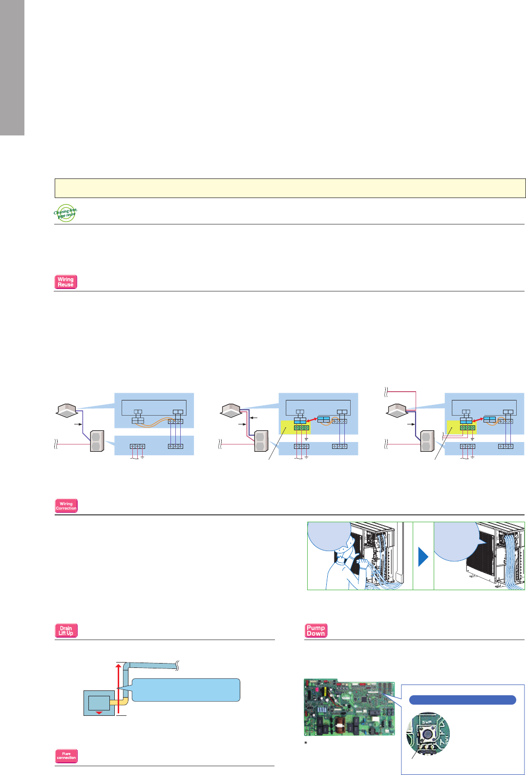
19
FUNCTIONS
(
3
)
Cleaning-free Pipe Reuse
Reuse of Existing Wiring
It is possible to reuse the same piping. It allows cleaning-free renewal of air conditioning systems that use R22 or R410 refrigerant.
The wiring method has been improved, making it possible to use methods different from that utilized for control and power supply. Units are
compatible with the dual harness control line/power line method and the separate power supply method. Using a power supply terminal kit, wire
can be efficiently reused at the time of system renewal regardless of the method the existing system uses.
*Optional. Usage may be limited due to wiring type diameter.
Wiring/Piping Correction Function*
The push of a single button is all that is required to confirm that
piping and wiring are properly connected. Corrections are made au-
tomatically if a wiring error is detected, eliminating the need for com-
plicated wiring confirmation work when expanding the number of
rooms served.
* This function cannot be used when the outdoor temperature is below 0°C.
The correction process requires 10–20 minutes, and only works when the unit is set
to the Cooling mode.
Drain Pump
A built-in drain pump enables drain piping to be raised.
Pump Down Switch
Enables smooth and easy recovery of refrigerant. Simply press the
“Pump Down” switch before moving or changing the unit.
Flare Connection
Flare connection to cooling pipe work is possible.
Wiring recycling problem solved! Compatible with other wiring connection methods*
Single Harness Control/Power Line Method
(Current method)
Indoor unit (factory-shipped condition) Indoor unit (factory-shipped condition)
Indoor unit
Control board
Power
Indoor/Outdoor unit
communication
Junction
connector
Outdoor unit
Indoor unit
Outdoor unit
to power
LN
S
1
S
2
S
3
S
1
S
2
S
3
Control/
Power
3 cores
Control/
Power
3 cores
Power supply
Dual Harness Control Line/Power Line Method
Control board
Junction connectors
replaced
Power
Indoor/Outdoor unit
communication
S
1
S
2
S
3
S
1
S
2
S
3
Power
2 cores
Control
2 cores
Power supply
Separate Power Supply Method
INSTALLATION
Pump Down Switch
Pump down switch
Push this switch to start/
stop refrigerant recovery
operation automatically.
(
Valve in refrigerant circuit
is opened/closed.)
Photo of Model PUHZ-P100
Outdoor unit control circuit board
Wiring
confirmation
is time
consuming.
The outdoor unit
matches
pipes and wiring.
Quick Clean Body
Exclusive Quick Clean Kit (Optional)
Our exclusive “Quick Clean Kit” can be easily connected to a household vacuum cleaner for quick and easy cleaning of the heat exchanger.*
*Wearing gloves is highly recommended when cleaning the heat exchanger, because touching it with bare hands can cause injury.
to power
LN
LN
Indoor unit
Outdoor unit
Control board
Junction connectors
replaced
Power
Indoor/Outdoor unit
communication
S
1
S
2
S
3
S
1
S
2
S
3
Control
2 cores
(polarised)
Power supply
Power supply
to power
to power
LN
LN
Power
2 cores
Control
2 cores
Control
2 cores
Built-in drain pump efficiently
pumps out water
Power supply terminal kit (optional)Power supply terminal kit (optional)
MAINTENANCE
Self-Diagnostic Function
(Check Code Display)
Check codes are displayed on the remote controller or the operation indicator to inform the user of malfunctions detected.
Failure Recall Function
Operation failures are recorded, allowing confirmation when needed.
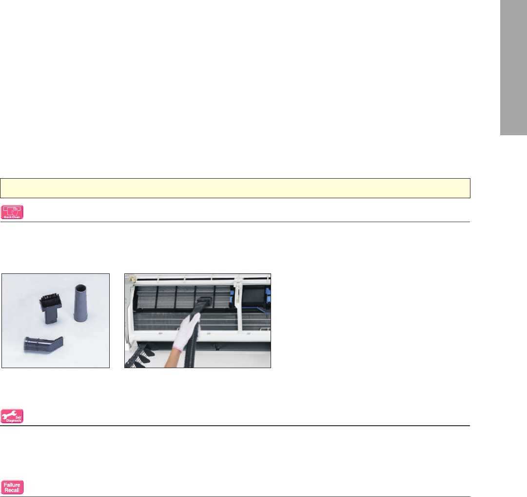
20
FUNCTIONS
(
3
)
Cleaning-free Pipe Reuse
Reuse of Existing Wiring
It is possible to reuse the same piping. It allows cleaning-free renewal of air conditioning systems that use R22 or R410 refrigerant.
The wiring method has been improved, making it possible to use methods different from that utilized for control and power supply. Units are
compatible with the dual harness control line/power line method and the separate power supply method. Using a power supply terminal kit, wire
can be efficiently reused at the time of system renewal regardless of the method the existing system uses.
*Optional. Usage may be limited due to wiring type diameter.
Wiring/Piping Correction Function*
The push of a single button is all that is required to confirm that
piping and wiring are properly connected. Corrections are made au-
tomatically if a wiring error is detected, eliminating the need for com-
plicated wiring confirmation work when expanding the number of
rooms served.
* This function cannot be used when the outdoor temperature is below 0°C.
The correction process requires 10–20 minutes, and only works when the unit is set
to the Cooling mode.
Drain Pump
A built-in drain pump enables drain piping to be raised.
Pump Down Switch
Enables smooth and easy recovery of refrigerant. Simply press the
“Pump Down” switch before moving or changing the unit.
Flare Connection
Flare connection to cooling pipe work is possible.
Wiring recycling problem solved! Compatible with other wiring connection methods*
Single Harness Control/Power Line Method
(Current method)
Indoor unit (factory-shipped condition) Indoor unit (factory-shipped condition)
Indoor unit
Control board
Power
Indoor/Outdoor unit
communication
Junction
connector
Outdoor unit
Indoor unit
Outdoor unit
to power
LN
S
1
S
2
S
3
S
1
S
2
S
3
Control/
Power
3 cores
Control/
Power
3 cores
Power supply
Dual Harness Control Line/Power Line Method
Control board
Junction connectors
replaced
Power
Indoor/Outdoor unit
communication
S
1
S
2
S
3
S
1
S
2
S
3
Power
2 cores
Control
2 cores
Power supply
Separate Power Supply Method
INSTALLATION
Pump Down Switch
Pump down switch
Push this switch to start/
stop refrigerant recovery
operation automatically.
(
Valve in refrigerant circuit
is opened/closed.)
Photo of Model PUHZ-P100
Outdoor unit control circuit board
Wiring
confirmation
is time
consuming.
The outdoor unit
matches
pipes and wiring.
Quick Clean Body
Exclusive Quick Clean Kit (Optional)
Our exclusive “Quick Clean Kit” can be easily connected to a household vacuum cleaner for quick and easy cleaning of the heat exchanger.*
*Wearing gloves is highly recommended when cleaning the heat exchanger, because touching it with bare hands can cause injury.
to power
LN
LN
Indoor unit
Outdoor unit
Control board
Junction connectors
replaced
Power
Indoor/Outdoor unit
communication
S
1
S
2
S
3
S
1
S
2
S
3
Control
2 cores
(polarised)
Power supply
Power supply
to power
to power
LN
LN
Power
2 cores
Control
2 cores
Control
2 cores
Built-in drain pump efficiently
pumps out water
Power supply terminal kit (optional)Power supply terminal kit (optional)
MAINTENANCE
Self-Diagnostic Function
(Check Code Display)
Check codes are displayed on the remote controller or the operation indicator to inform the user of malfunctions detected.
Failure Recall Function
Operation failures are recorded, allowing confirmation when needed.
21
FUNCTION LIST
(
1
)
\
Opt
Opt
Opt
Opt
Opt
*1
2E
Opt
Opt
Opt
Opt
Opt
*2
*1
Opt
Opt
Opt
Opt
Opt
*2
72/83VA
4E
72/83VA
72
*1
4E
Opt
Opt
Opt
Opt
Opt
*2
*1
Opt
Opt
Opt
Opt
Opt
*2
*1
Opt
Opt
Opt
Opt
Opt
*2
VEW
Opt
Opt
Opt
Opt
Opt
Opt
VEW
Opt
*1
2E
Opt
Opt
Opt
Opt
Opt
*2
VEW
Opt
*1
Opt
Opt
Opt
Opt
Opt
*2
72/83VA
4E
72/83VA
72
VEW
Opt
*1
4E
Opt
Opt
Opt
Opt
Opt
*2
VEW
Opt
*1
Opt
Opt
Opt
Opt
Opt
*2
VEW
Opt
\
*1
Opt
Opt
Opt
Opt
Opt
*2
Opt
Opt
Opt
Opt
Opt
Opt
Opt
*1
2E
Opt
Opt
Opt
Opt
Opt
*2
Opt
*1
Opt
Opt
Opt
Opt
Opt
*2
72/83VA
4E
72/83VA
72
Opt
*1
4E
Opt
Opt
Opt
Opt
Opt
*2
Opt
*1
Opt
Opt
Opt
Opt
Opt
*2
Opt
*1
Opt
Opt
Opt
Opt
Opt
*2
*1
2E
Opt
Opt
Opt
Opt
Opt
*2
*1
Opt
Opt
Opt
Opt
Opt
*2
72/83VA
4E
72/83VA
72
*1
4E
Opt
Opt
Opt
Opt
Opt
*2
*1
Opt
Opt
Opt
Opt
Opt
*2
*1
Opt
Opt
Opt
Opt
Opt
*2
35
50
*1
2E
Opt
Opt
Opt
Opt
Opt
*2
*1
Opt
Opt
Opt
Opt
Opt
*2
72/83VA
4E
72/83VA
72
*1
4E
Opt
Opt
Opt
Opt
Opt
*2
*1
Opt
Opt
Opt
Opt
Opt
*2
*1
Opt
Opt
Opt
Opt
Opt
*2
Opt
Opt
Opt
Opt
Opt
Opt
Opt
*1
Opt
Opt
Opt
Opt
Opt
*2
72/83VA
4E
72/83VA
72
Opt
*1
4E
Opt
Opt
Opt
Opt
Opt
*2
Opt
*1
Opt
Opt
Opt
Opt
Opt
*2
Opt
*1
Opt
Opt
Opt
Opt
Opt
*2
*2
*2
*2
Opt
Opt
*1
2E
Opt
Opt
Opt
Opt
Opt
*2
Opt
Opt
*1
Opt
Opt
Opt
Opt
Opt
*2
72/83VA
4E
72/83VA
72
Opt
Opt
*1
4E
Opt
Opt
Opt
Opt
Opt
*2
Opt
Opt
*1
Opt
Opt
Opt
Opt
Opt
*2
Opt
Opt
*1
Opt
Opt
Opt
Opt
Opt
*2
Opt
Opt
Opt
Opt
Opt
Opt
*1
2E
Opt
Opt
Opt
Opt
Opt
*2
Opt
*1
Opt
Opt
Opt
Opt
Opt
*2
Opt
72/83VA
4E
72/83VA
72
*1
4E
Opt
Opt
Opt
Opt
Opt
*2
Opt
*1
Opt
Opt
Opt
Opt
Opt
*2
Opt
*1
Opt
Opt
Opt
Opt
Opt
*2
Opt
DC Inverter
Joint Lap DC Motor
Magnetic Flux Vector Sine Wave Drive
Reluctance DC Rotary Compressor
Highly Efficient DC Scroll Compressor
Heating Caulking (Compressor)
DC Fan Motor
Vector-Wave Eco Inverter
PAM (Pulse Amplitude Modulation)
Power Receiver and Twin LEV Control
Grooved Piping
Felt Temperature Control (3D i-see Sensor)
AREA Temperature Monitor
Econo Cool Energy-saving Feature
Standby Power Consumption Cut
Demand Function
Pure White
Auto Vane
Plasma Quad
Fresh-air Intake
Anti-allergy Enzyme Filter
Electrostatic Anti-allergy Enzyme Filter
High-efficiency Filter
Catechin Filter
Nano Platinum Filter
Oil Mist Filter
Long-life Filter
Filter Check Signal
Double Vane
Horizontal Vane
Vertical Vane
High Ceiling Mode
Silent Mode
Auto Fan Speed Mode
On/off Operation Timer
"i save" Mode
Auto Changeover
Auto Restart
Low-temperature Cooling
Low-noise Operation (Outdoor Unit)
Ampere Limit Adjustment
Operation Lock
Built-in Weekly Timer Function
Rotation, Back-up and 2nd Stage Cut-in Functions
PAR-32MAA Control *3
PAC-YT52CRA Control *3
Centralised On/Off Control *3
System Group Control *3
M-NET Connection *3
COMPO *4
MXZ Connection
Cleaning-free Pipe Reuse
Reuse of Existing Wiring
Wiring/Piping Correction Function
Drain Pump
Pump Down Switch
Flare Connection
Self-Diagnosis Function (Check Code Display)
Failure Recall Function
Indoor unit
Outdoor unit
MSZ-FH25/35/50VE MSZ-SF25/35/42/50VE2MSZ-EF18/22/25/35/42/50VE2(W)(B)(S) MSZ-SF15/20VA MFZ-KJ25/35/50VE MLZ-KA25/35/50VA SLZ-KF25/35/50/60VA SEZ-KD25/35/50/60/71VAL/VAQ
MUZ
-FH
MXZ
-2D/E
MXZ
-3D
MXZ
-4D/E
MXZ
-5E
MXZ
-6D
MUZ
-SF
MUZ
-EF
MXZ
-2D/E
MXZ
-3D
MXZ
-4D/E
MXZ
-5E
MXZ
-6D
MXZ
-2D/E
MXZ
-3D
MXZ
-4D/E
MXZ
-5E
MXZ
-6D
MXZ
-2D/E
MXZ
-3D
MXZ
-4D/E
MXZ
-5E
MXZ
-6D
MUZ
-HJ
MXZ
-2HJ
MXZ
-3HJ
MUZ
-HJ
MSZ-
HJ60/
71VA
MXZ
-2D/E
*1
Opt
Opt
Opt
Opt
Opt
MUFZ
-KJ
MXZ
-3D
MXZ
-4D/E
MXZ
-5E
MXZ
-6D
MSZ-GF60/71VE
MSZ-HJ25/35/50VA
MUZ
-GF
MXZ
-3D
MXZ
-4D/E
MXZ
-5E
MXZ
-6D
MXZ
-2D/E
MXZ
-3D
MXZ
-4D/E
MXZ
-5E
MXZ
-6D
SUZ
-KA
MXZ
-2D/E
MXZ
-3D
MXZ
-4D/E
MXZ
-5E
MXZ
-6D
SUZ
-KA
MXZ
-2D/E
MXZ
-3D
MXZ
-4D/E
MXZ
-5E
MXZ
-6D
M SERIES M SERIES S SERIES
Technology
i-see Sensor
Attractive
Energy
Saving
Air Quality
Air
Distribution
Convenience
System
Control
Installation
Maintenance
Functions
Combination
Category Icon
• The figures listed in the table are "only when combined with an outdoor unit with the appropriate capacity range".
• Opt: Separate parts must be purchased.
*1 When multiple indoor units connected to an MXZ outdoor unit are running at the same time, simultaneous cooling and heating is not possible.
*2 For the possible connectivity of MXZ outdoor units and indoor units, please refer to the list on page 93 for details.
*3 Please refer to "System Control" on pages 29-30 for details.
*4 Please refer to page 18 for details.
*5 SLZ-KF60VA cannot be connected to MXZ.
Opt
Opt
Opt
Opt
Opt
Opt
Opt
Opt
Opt
*1
2E
Opt
Opt
Opt
Opt
Opt
*2
Opt
Opt
*1
Opt
Opt
Opt
Opt
Opt
*2
72/83VA
4E
72/83VA
72
Opt
Opt
*1
4E
Opt
Opt
Opt
Opt
Opt
*2
Opt
Opt
*1
Opt
Opt
Opt
Opt
Opt
*2
Opt
Opt
*1
Opt
Opt
Opt
Opt
Opt
*2
Category
Icon
M series M series S series
Combination
Indoor unit
MSZ-FH25/35/50VE MSZ-EF18/22/25/35/42/50VE2(W)(B)(S) MSZ-SF15/20VA MSZ-SF25/35/42/50VE2 MSZ-GF60/71VE MSZ-DM25/35VA MSZ-HJ25/35/50VA
MSZ-
HJ60/
71VA
MFZ-KJ25/35/50VE MLZ-KA25/35/50VA SLZ-KF25/35/50/60VA *5 SEZ-KD25/35/50/60/71VAL/VAQ
Outdoor unit
MUZ
-FH
MXZ
-2D/E
MXZ
-3D
MXZ
-4D/E
MXZ
-5E
MXZ
-6D
MUZ
-EF
MXZ
-2D/E
MXZ
-3D
MXZ
-4D/E
MXZ
-5E
MXZ
-6D
MXZ
-2D/E
MXZ
-3D
MXZ
-4D/E
MXZ
-5E
MXZ
-6D
MUZ
-SF
MXZ
-2D/E
MXZ
-3D
MXZ
-4D/E
MXZ
-5E
MXZ
-6D
MUZ
-GF
MXZ
-3D
MXZ
-4D/E
MXZ
-5E
MXZ
-6D
MUZ
-DM
MXZ
-2DM
MXZ
-3DM
MUZ
-HJ
MXZ
-2DM
MXZ
-3DM
MUZ
-HJ
MUFZ
-KJ
MXZ
-2D/E
MXZ -3D
MXZ
-4D/E
MXZ -5E
MXZ
-6D
MXZ
-2D/E
MXZ -3D
MXZ
-4D/E
MXZ -5E
MXZ
-6D
SUZ -KA
MXZ
-2D/E
MXZ -3D
MXZ
-4D/E
MXZ -5E
MXZ
-6D
SUZ -KA
MXZ
-2D/E
MXZ -3D
MXZ
-4D/E
MXZ -5E
MXZ
-6D
Technology
DC Inverter
● ● ● ● ● ● ● ● ● ● ● ● ● ● ● ● ● ● ● ● ● ● ● ● ● ● ● ● ● ● ● ● ● ● ● ● ● ● ● ● ● ● ● ● ● ● ● ● ● ● ● ● ● ● ● ● ● ●
Joint Lap DC Motor
● ● ●
72/83VA
● ● ● ●
72/83VA
● ● ●
72/83VA
● ● ● ●
72/83VA
● ● ●
72/83VA
● ● ● ● ● ● ● ● ● ● ●
72/83VA
● ● ●
72/83VA
● ● ● ●
72/83VA
● ● ● ●
72/83VA
●
Magnetic Flux Vector Sine Wave Drive
Reluctance DC Rotary Compressor 4E
● ●
4E
● ●
4E
● ●
4E
● ●
4E
● ●
4E
● ●
4E
● ●
4E
● ●
4E
● ●
Highly Efficient DC Scroll Compressor
Heating Caulking (Compressor)
● ● ●
72/83VA
● ● ● ●
72/83VA
● ● ●
72/83VA
● ● ●
72/83VA
● ●
72/83VA
●
35
● ●
35
● ● ● ● ● ●
72/83VA
● ● ●
72/83VA
● ● ● ●
72/83VA
● ● ● ●
72/83VA
●
DC Fan Motor
● ● ● ● ● ● ● ● ● ● ● ● ● ● ● ● ● ● ● ● ● ● ● ● ● ● ● ● ● ● ● ● ● ● ● ● ● ● ● ● ● ● ● ● ● ● ● ● ● ● ● ● ● ● ● ● ● ●
Vector-Wave Eco Inverter
PAM (Pulse Amplitude Modulation)
● ● ● ● ● ● ● ● ● ● ● ● ● ● ● ● ● ● ● ● ● ● ● ● ● ● ● ● ● ● ● ● ● ● ● ● ● ● ● ● ● ● ● ● ● ● ● ● ● ● ● ● ● ● ● ● ● ●
Power Receiver and Twin LEV Control
●
72
●
72
●
72
●
72
●
72
● ● ●
72
●
72
●
72
●
72
Grooved Piping
● ● ● ● ● ● ● ● ● ● ● ● ● ● ● ● ● ● ● ● ● ● ● ● ● ● ● ● ● ● ● ● ● ● ● ● ● ● ● ● ● ● ● ● ● ● ● ● ● ● ● ● ● ● ● ● ● ●
Function
I-see Sensor
Felt Temperature Control (3D i-see Sensor)
● ● ● ● ● ●
Opt Opt Opt Opt Opt Opt
AREA Temperature Monitor
● ● ● ● ● ●
Opt Opt Opt Opt Opt Opt
Energy Saving
Econo Cool Energy-saving Feature
● ● ● ● ● ● ● ● ● ● ● ● ● ● ● ● ● ● ● ● ● ● ● ● ● ● ● ● ● ● ● ● ● ● ● ● ● ● ● ● ● ● ● ● ●
Standby Power Consumption Cut
● ● ● ● ●
Demand Function
Attractive
Pure White
● ● ● ● ● ●
VIEW VIEW VIEW VIEW VIEW VIEW
● ● ● ● ● ● ● ● ● ● ● ● ● ● ● ● ● ● ● ● ● ● ● ● ● ● ● ● ● ● ● ● ● ● ●
Auto Vane
● ● ● ● ● ● ● ● ● ● ● ● ● ● ● ● ● ● ● ● ● ● ● ● ● ● ● ● ● ● ● ● ● ● ● ● ● ● ● ● ● ● ● ● ● ● ● ● ● ● ● ●
Air Quality
Plasma Quad
● ● ● ● ● ●
Fresh-air Intake
● ● ● ● ● ●
Anti-allergy Enzyme Filter
● ● ● ● ● ●
Opt Opt Opt Opt Opt
Electrostatic Anti-allergy Enzyme Filter
● ● ● ● ● ●
Opt Opt Opt Opt Opt Opt Opt Opt Opt Opt Opt Opt Opt Opt Opt Opt Opt
High-efficiency Filter
Catechin Filter Opt Opt Opt Opt Opt
Nano Platinum Filter
● ● ● ● ● ● ● ● ● ● ● ● ● ● ● ● ●
Oil Mist Filter
Long-life Filter
● ● ● ● ● ●
Filter Check Signal
● ● ● ● ● ●
Air
Distribution
Double Vane
● ● ● ● ● ●
Horizontal Vane
● ● ● ● ● ● ● ● ● ● ● ● ● ● ● ● ● ● ● ● ● ● ● ● ● ● ● ● ● ● ● ● ● ● ● ● ● ● ● ● ● ● ● ● ● ● ● ● ● ● ● ●
Vertical Vane
● ● ● ● ● ● ● ● ● ● ● ● ● ● ● ● ●
High Ceiling Mode
● ● ● ● ● ● ● ● ● ● ●
Silent Mode
Auto Fan Speed Mode
● ● ● ● ● ● ● ● ● ● ● ● ● ● ● ● ● ● ● ● ● ● ● ● ● ● ● ● ● ● ● ● ● ● ● ● ● ● ● ● ● ● ● ● ● ● ● ● ● ● ● ● ● ● ● ● ● ●
Convenience
On/off Operation Timer
● ● ● ● ● ● ● ● ● ● ● ● ● ● ● ● ● ● ● ● ● ● ● ● ● ● ● ● ● ● ● ● ● ● ● ● ● ● ● ● ● ● ● ● ● ● ● ● ● ● ● ● ● ● ● ● ● ●
"i save" Mode
● ● ● ● ● ● ● ● ● ● ● ● ● ● ● ● ● ● ● ● ● ● ● ● ● ● ● ● ● ● ● ● ● ●
Auto Changeover
● ●*1 ●*1 ●*1 ●*1 ●*1 ● ●*1 ●*1 ●*1 ●*1 ●*1 ●*1 ●*1 ●*1 ●*1 ●*1 ● ●*1 ●*1 ●*1 ●*1 ●*1 ● ●*1 ●*1 ●*1 ●*1 ●*1 ●*1 ●*1 ●*1 ●*1 ●*1 ●*1 ●*1 ●*1 ●*1 ●*1 ● ●*1 ●*1 ●*1 ●*1 ●*1 ● ●*1 ●*1 ●*1 ●*1 ●*1
Auto Restart
● ● ● ● ● ● ● ● ● ● ● ● ● ● ● ● ● ● ● ● ● ● ● ● ● ● ● ● ● ● ● ● ● ● ● ● ● ● ● ● ● ● ● ● ● ● ● ● ● ● ● ● ● ● ● ● ● ●
Low-temperature Cooling
● ● ● ● ● ● ● ● ● ● ● ● ● ● ● ● ● ● ● ● ● ● ● ● ● ● ● ● ● ● ● ● ● ● ● ● ● ● ● ● ● ● ● ● ● ● ● ● ● ● ● ● ● ● ● ●
Low-noise Operation (Outdoor Unit)
● ● ● ● ● ● ● ● ● ● ● ● ● ● ● ● ● ● ● ● ● ● ● ● ● ● ● ● ● ● ● ● ● ● ● ● ● ● ● ● ● ● ● ● ● ● ● ●
Ampere Limit Adjustment 2E 4E
● ●
2E 4E
● ●
2E 4E
● ●
2E 4E
● ●
4E
● ● ● ● ● ●
2E 4E
● ●
2E 4E
● ●
2E 4E
● ●
2E 4E
● ●
Operation Lock
● ● ● ● ● ● ● ● ● ● ● ● ● ● ● ● ● ● ● ● ● ● ● ● ● ● ● ● ● ● ● ● ● ● ● ● ● ● ● ● ● ● ● ● ● ● ● ●
Built-in Weekly Timer Function
● ● ● ● ● ● ● ● ● ● ● ● ● ● ● ● ● ● ● ● ● ● ● ● ● ● ● ● ●
Rotation, Back-up and 2nd Stage Cut-in
Functions
System Control
PAR-32MAA Control *3 Opt Opt Opt Opt Opt Opt Opt Opt Opt Opt Opt Opt Opt Opt Opt Opt Opt Opt Opt Opt Opt Opt Opt Opt Opt Opt Opt Opt Opt Opt Opt Opt Opt Opt Opt Opt Opt Opt Opt Opt Opt Opt Opt Opt Opt Opt Opt Opt Opt Opt Opt Opt Opt Opt
PAC-YT52CRA Control *3 Opt Opt Opt Opt Opt Opt Opt Opt Opt Opt Opt Opt Opt Opt Opt Opt Opt Opt Opt Opt Opt Opt Opt Opt Opt Opt Opt Opt Opt Opt Opt Opt Opt Opt Opt Opt Opt Opt Opt Opt Opt Opt Opt Opt Opt Opt Opt Opt Opt Opt Opt Opt Opt Opt
Centralised On/Off Control *3 Opt Opt Opt Opt Opt Opt Opt Opt Opt Opt Opt Opt Opt Opt Opt Opt Opt Opt Opt Opt Opt Opt Opt Opt Opt Opt Opt Opt Opt Opt Opt Opt Opt Opt Opt Opt Opt Opt Opt Opt Opt Opt Opt Opt Opt Opt Opt Opt Opt Opt Opt Opt Opt Opt
System Group Control *3 Opt Opt Opt Opt Opt Opt Opt Opt Opt Opt Opt Opt Opt Opt Opt Opt Opt Opt Opt Opt Opt Opt Opt Opt Opt Opt Opt Opt Opt Opt Opt Opt Opt Opt Opt Opt Opt Opt Opt Opt Opt Opt Opt Opt Opt Opt Opt Opt Opt Opt Opt Opt Opt Opt
M-NET Connection *3 Opt Opt Opt Opt Opt Opt Opt Opt Opt Opt Opt Opt Opt Opt Opt Opt Opt Opt Opt Opt Opt Opt Opt Opt Opt Opt Opt Opt Opt Opt Opt Opt Opt Opt Opt Opt Opt Opt Opt Opt Opt Opt Opt Opt Opt Opt Opt Opt Opt Opt Opt Opt Opt Opt
COMPO *4
MXZ Connection
●*2 ●*2 ●*2 ●*2 ●*2 ●*2 ●*2 ●*2 ●*2 ●*2 ●*2 ●*2 ●*2 ●*2 ●*2 ●*2 ●*2 ●*2 ●*2 ●*2 ●*2 ●*2 ●*2 ●*2 ●*2 ●*2 ●*2 ●*2 ●*2 ●*2 ●*2 ●*2 ●*2 ●*2 ●*2 ●*2 ●*2 ●*2 ●*2 ●*2 ●*2 ●*2 ●*2 ●*2 ●*2 ●*2 ●*2 ●*2
Installation
Cleaning-free Pipe Reuse
● ● ● ● ● ● ● ● ● ● ● ● ● ● ● ● ● ● ● ● ● ● ● ● ● ● ● ● ● ● ● ● ● ● ● ● ● ● ● ● ● ● ● ● ● ● ● ● ● ● ● ● ● ● ● ● ● ●
Reuse of Existing Wiring
Wiring/Piping Correction Function
● ● ● ● ● ● ● ● ● ● ● ● ● ● ● ● ● ● ● ● ● ● ● ● ● ● ● ● ● ● ● ● ● ● ● ● ● ● ● ● ● ● ● ● ● ● ●
Drain Pump
● ● ● ● ● ● ● ● ● ● ●
Opt Opt Opt Opt Opt Opt
Pump Down Switch
Flare Connection
● ● ● ● ● ● ● ● ● ● ● ● ● ● ● ● ● ● ● ● ● ● ● ● ● ● ● ● ● ● ● ● ● ● ● ● ● ● ● ● ● ● ● ● ● ● ● ● ● ● ● ● ● ● ● ● ● ●
Maintenance
Self-Diagnosis Function (Check Code
Display)
● ● ● ● ● ● ● ● ● ● ● ● ● ● ● ● ● ● ● ● ● ● ● ● ● ● ● ● ● ● ● ● ● ● ● ● ● ● ● ● ● ● ● ● ● ● ● ● ● ● ● ● ● ● ● ● ● ●
Failure Recall Function
● ● ● ● ● ● ● ● ● ● ● ● ● ● ● ● ● ● ● ● ● ● ● ● ● ● ● ● ● ● ● ● ● ● ● ● ● ● ● ● ● ● ● ● ● ● ● ● ● ● ● ● ● ● ● ● ● ●
----
22
FUNCTION LIST
(
1
)
\
Opt
Opt
Opt
Opt
Opt
*1
2E
Opt
Opt
Opt
Opt
Opt
*2
*1
Opt
Opt
Opt
Opt
Opt
*2
72/83VA
4E
72/83VA
72
*1
4E
Opt
Opt
Opt
Opt
Opt
*2
*1
Opt
Opt
Opt
Opt
Opt
*2
*1
Opt
Opt
Opt
Opt
Opt
*2
VEW
Opt
Opt
Opt
Opt
Opt
Opt
VEW
Opt
*1
2E
Opt
Opt
Opt
Opt
Opt
*2
VEW
Opt
*1
Opt
Opt
Opt
Opt
Opt
*2
72/83VA
4E
72/83VA
72
VEW
Opt
*1
4E
Opt
Opt
Opt
Opt
Opt
*2
VEW
Opt
*1
Opt
Opt
Opt
Opt
Opt
*2
VEW
Opt
\
*1
Opt
Opt
Opt
Opt
Opt
*2
Opt
Opt
Opt
Opt
Opt
Opt
Opt
*1
2E
Opt
Opt
Opt
Opt
Opt
*2
Opt
*1
Opt
Opt
Opt
Opt
Opt
*2
72/83VA
4E
72/83VA
72
Opt
*1
4E
Opt
Opt
Opt
Opt
Opt
*2
Opt
*1
Opt
Opt
Opt
Opt
Opt
*2
Opt
*1
Opt
Opt
Opt
Opt
Opt
*2
*1
2E
Opt
Opt
Opt
Opt
Opt
*2
*1
Opt
Opt
Opt
Opt
Opt
*2
72/83VA
4E
72/83VA
72
*1
4E
Opt
Opt
Opt
Opt
Opt
*2
*1
Opt
Opt
Opt
Opt
Opt
*2
*1
Opt
Opt
Opt
Opt
Opt
*2
35
50
*1
2E
Opt
Opt
Opt
Opt
Opt
*2
*1
Opt
Opt
Opt
Opt
Opt
*2
72/83VA
4E
72/83VA
72
*1
4E
Opt
Opt
Opt
Opt
Opt
*2
*1
Opt
Opt
Opt
Opt
Opt
*2
*1
Opt
Opt
Opt
Opt
Opt
*2
Opt
Opt
Opt
Opt
Opt
Opt
Opt
*1
Opt
Opt
Opt
Opt
Opt
*2
72/83VA
4E
72/83VA
72
Opt
*1
4E
Opt
Opt
Opt
Opt
Opt
*2
Opt
*1
Opt
Opt
Opt
Opt
Opt
*2
Opt
*1
Opt
Opt
Opt
Opt
Opt
*2
*2
*2
*2
Opt
Opt
*1
2E
Opt
Opt
Opt
Opt
Opt
*2
Opt
Opt
*1
Opt
Opt
Opt
Opt
Opt
*2
72/83VA
4E
72/83VA
72
Opt
Opt
*1
4E
Opt
Opt
Opt
Opt
Opt
*2
Opt
Opt
*1
Opt
Opt
Opt
Opt
Opt
*2
Opt
Opt
*1
Opt
Opt
Opt
Opt
Opt
*2
Opt
Opt
Opt
Opt
Opt
Opt
*1
2E
Opt
Opt
Opt
Opt
Opt
*2
Opt
*1
Opt
Opt
Opt
Opt
Opt
*2
Opt
72/83VA
4E
72/83VA
72
*1
4E
Opt
Opt
Opt
Opt
Opt
*2
Opt
*1
Opt
Opt
Opt
Opt
Opt
*2
Opt
*1
Opt
Opt
Opt
Opt
Opt
*2
Opt
DC Inverter
Joint Lap DC Motor
Magnetic Flux Vector Sine Wave Drive
Reluctance DC Rotary Compressor
Highly Efficient DC Scroll Compressor
Heating Caulking (Compressor)
DC Fan Motor
Vector-Wave Eco Inverter
PAM (Pulse Amplitude Modulation)
Power Receiver and Twin LEV Control
Grooved Piping
Felt Temperature Control (3D i-see Sensor)
AREA Temperature Monitor
Econo Cool Energy-saving Feature
Standby Power Consumption Cut
Demand Function
Pure White
Auto Vane
Plasma Quad
Fresh-air Intake
Anti-allergy Enzyme Filter
Electrostatic Anti-allergy Enzyme Filter
High-efficiency Filter
Catechin Filter
Nano Platinum Filter
Oil Mist Filter
Long-life Filter
Filter Check Signal
Double Vane
Horizontal Vane
Vertical Vane
High Ceiling Mode
Silent Mode
Auto Fan Speed Mode
On/off Operation Timer
"i save" Mode
Auto Changeover
Auto Restart
Low-temperature Cooling
Low-noise Operation (Outdoor Unit)
Ampere Limit Adjustment
Operation Lock
Built-in Weekly Timer Function
Rotation, Back-up and 2nd Stage Cut-in Functions
PAR-32MAA Control *3
PAC-YT52CRA Control *3
Centralised On/Off Control *3
System Group Control *3
M-NET Connection *3
COMPO *4
MXZ Connection
Cleaning-free Pipe Reuse
Reuse of Existing Wiring
Wiring/Piping Correction Function
Drain Pump
Pump Down Switch
Flare Connection
Self-Diagnosis Function (Check Code Display)
Failure Recall Function
Indoor unit
Outdoor unit
MSZ-FH25/35/50VE MSZ-SF25/35/42/50VE2MSZ-EF18/22/25/35/42/50VE2(W)(B)(S) MSZ-SF15/20VA MFZ-KJ25/35/50VE MLZ-KA25/35/50VA SLZ-KF25/35/50/60VA SEZ-KD25/35/50/60/71VAL/VAQ
MUZ
-FH
MXZ
-2D/E
MXZ
-3D
MXZ
-4D/E
MXZ
-5E
MXZ
-6D
MUZ
-SF
MUZ
-EF
MXZ
-2D/E
MXZ
-3D
MXZ
-4D/E
MXZ
-5E
MXZ
-6D
MXZ
-2D/E
MXZ
-3D
MXZ
-4D/E
MXZ
-5E
MXZ
-6D
MXZ
-2D/E
MXZ
-3D
MXZ
-4D/E
MXZ
-5E
MXZ
-6D
MUZ
-HJ
MXZ
-2HJ
MXZ
-3HJ
MUZ
-HJ
MSZ-
HJ60/
71VA
MXZ
-2D/E
*1
Opt
Opt
Opt
Opt
Opt
MUFZ
-KJ
MXZ
-3D
MXZ
-4D/E
MXZ
-5E
MXZ
-6D
MSZ-GF60/71VE
MSZ-HJ25/35/50VA
MUZ
-GF
MXZ
-3D
MXZ
-4D/E
MXZ
-5E
MXZ
-6D
MXZ
-2D/E
MXZ
-3D
MXZ
-4D/E
MXZ
-5E
MXZ
-6D
SUZ
-KA
MXZ
-2D/E
MXZ
-3D
MXZ
-4D/E
MXZ
-5E
MXZ
-6D
SUZ
-KA
MXZ
-2D/E
MXZ
-3D
MXZ
-4D/E
MXZ
-5E
MXZ
-6D
M SERIES M SERIES S SERIES
Technology
i-see Sensor
Attractive
Energy
Saving
Air Quality
Air
Distribution
Convenience
System
Control
Installation
Maintenance
Functions
Combination
Category Icon
• The figures listed in the table are "only when combined with an outdoor unit with the appropriate capacity range".
• Opt: Separate parts must be purchased.
*1 When multiple indoor units connected to an MXZ outdoor unit are running at the same time, simultaneous cooling and heating is not possible.
*2 For the possible connectivity of MXZ outdoor units and indoor units, please refer to the list on page 93 for details.
*3 Please refer to "System Control" on pages 29-30 for details.
*4 Please refer to page 18 for details.
*5 SLZ-KF60VA cannot be connected to MXZ.
Opt
Opt
Opt
Opt
Opt
Opt
Opt
Opt
Opt
*1
2E
Opt
Opt
Opt
Opt
Opt
*2
Opt
Opt
*1
Opt
Opt
Opt
Opt
Opt
*2
72/83VA
4E
72/83VA
72
Opt
Opt
*1
4E
Opt
Opt
Opt
Opt
Opt
*2
Opt
Opt
*1
Opt
Opt
Opt
Opt
Opt
*2
Opt
Opt
*1
Opt
Opt
Opt
Opt
Opt
*2
Category
Icon
M series M series S series
Combination
Indoor unit
MSZ-FH25/35/50VE MSZ-EF18/22/25/35/42/50VE2(W)(B)(S) MSZ-SF15/20VA MSZ-SF25/35/42/50VE2 MSZ-GF60/71VE MSZ-DM25/35VA MSZ-HJ25/35/50VA
MSZ-
HJ60/
71VA
MFZ-KJ25/35/50VE MLZ-KA25/35/50VA SLZ-KF25/35/50/60VA *5 SEZ-KD25/35/50/60/71VAL/VAQ
Outdoor unit
MUZ
-FH
MXZ
-2D/E
MXZ
-3D
MXZ
-4D/E
MXZ
-5E
MXZ
-6D
MUZ
-EF
MXZ
-2D/E
MXZ
-3D
MXZ
-4D/E
MXZ
-5E
MXZ
-6D
MXZ
-2D/E
MXZ
-3D
MXZ
-4D/E
MXZ
-5E
MXZ
-6D
MUZ
-SF
MXZ
-2D/E
MXZ
-3D
MXZ
-4D/E
MXZ
-5E
MXZ
-6D
MUZ
-GF
MXZ
-3D
MXZ
-4D/E
MXZ
-5E
MXZ
-6D
MUZ
-DM
MXZ
-2DM
MXZ
-3DM
MUZ
-HJ
MXZ
-2DM
MXZ
-3DM
MUZ
-HJ
MUFZ
-KJ
MXZ
-2D/E
MXZ -3D
MXZ
-4D/E
MXZ -5E
MXZ
-6D
MXZ
-2D/E
MXZ -3D
MXZ
-4D/E
MXZ -5E
MXZ
-6D
SUZ -KA
MXZ
-2D/E
MXZ -3D
MXZ
-4D/E
MXZ -5E
MXZ
-6D
SUZ -KA
MXZ
-2D/E
MXZ -3D
MXZ
-4D/E
MXZ -5E
MXZ
-6D
Technology
DC Inverter
● ● ● ● ● ● ● ● ● ● ● ● ● ● ● ● ● ● ● ● ● ● ● ● ● ● ● ● ● ● ● ● ● ● ● ● ● ● ● ● ● ● ● ● ● ● ● ● ● ● ● ● ● ● ● ● ● ●
Joint Lap DC Motor
● ● ●
72/83VA
● ● ● ●
72/83VA
● ● ●
72/83VA
● ● ● ●
72/83VA
● ● ●
72/83VA
● ● ● ● ● ● ● ● ● ● ●
72/83VA
● ● ●
72/83VA
● ● ● ●
72/83VA
● ● ● ●
72/83VA
●
Magnetic Flux Vector Sine Wave Drive
Reluctance DC Rotary Compressor 4E
● ●
4E
● ●
4E
● ●
4E
● ●
4E
● ●
4E
● ●
4E
● ●
4E
● ●
4E
● ●
Highly Efficient DC Scroll Compressor
Heating Caulking (Compressor)
● ● ●
72/83VA
● ● ● ●
72/83VA
● ● ●
72/83VA
● ● ●
72/83VA
● ●
72/83VA
●
35
● ●
35
● ● ● ● ● ●
72/83VA
● ● ●
72/83VA
● ● ● ●
72/83VA
● ● ● ●
72/83VA
●
DC Fan Motor
● ● ● ● ● ● ● ● ● ● ● ● ● ● ● ● ● ● ● ● ● ● ● ● ● ● ● ● ● ● ● ● ● ● ● ● ● ● ● ● ● ● ● ● ● ● ● ● ● ● ● ● ● ● ● ● ● ●
Vector-Wave Eco Inverter
PAM (Pulse Amplitude Modulation)
● ● ● ● ● ● ● ● ● ● ● ● ● ● ● ● ● ● ● ● ● ● ● ● ● ● ● ● ● ● ● ● ● ● ● ● ● ● ● ● ● ● ● ● ● ● ● ● ● ● ● ● ● ● ● ● ● ●
Power Receiver and Twin LEV Control
●
72
●
72
●
72
●
72
●
72
● ● ●
72
●
72
●
72
●
72
Grooved Piping
● ● ● ● ● ● ● ● ● ● ● ● ● ● ● ● ● ● ● ● ● ● ● ● ● ● ● ● ● ● ● ● ● ● ● ● ● ● ● ● ● ● ● ● ● ● ● ● ● ● ● ● ● ● ● ● ● ●
Function
I-see Sensor
Felt Temperature Control (3D i-see Sensor)
● ● ● ● ● ●
Opt Opt Opt Opt Opt Opt
AREA Temperature Monitor
● ● ● ● ● ●
Opt Opt Opt Opt Opt Opt
Energy Saving
Econo Cool Energy-saving Feature
● ● ● ● ● ● ● ● ● ● ● ● ● ● ● ● ● ● ● ● ● ● ● ● ● ● ● ● ● ● ● ● ● ● ● ● ● ● ● ● ● ● ● ● ●
Standby Power Consumption Cut
● ● ● ● ●
Demand Function
Attractive
Pure White
● ● ● ● ● ●
VIEW VIEW VIEW VIEW VIEW VIEW
● ● ● ● ● ● ● ● ● ● ● ● ● ● ● ● ● ● ● ● ● ● ● ● ● ● ● ● ● ● ● ● ● ● ●
Auto Vane
● ● ● ● ● ● ● ● ● ● ● ● ● ● ● ● ● ● ● ● ● ● ● ● ● ● ● ● ● ● ● ● ● ● ● ● ● ● ● ● ● ● ● ● ● ● ● ● ● ● ● ●
Air Quality
Plasma Quad
● ● ● ● ● ●
Fresh-air Intake
● ● ● ● ● ●
Anti-allergy Enzyme Filter
● ● ● ● ● ●
Opt Opt Opt Opt Opt
Electrostatic Anti-allergy Enzyme Filter
● ● ● ● ● ●
Opt Opt Opt Opt Opt Opt Opt Opt Opt Opt Opt Opt Opt Opt Opt Opt Opt
High-efficiency Filter
Catechin Filter Opt Opt Opt Opt Opt
Nano Platinum Filter
● ● ● ● ● ● ● ● ● ● ● ● ● ● ● ● ●
Oil Mist Filter
Long-life Filter
● ● ● ● ● ●
Filter Check Signal
● ● ● ● ● ●
Air
Distribution
Double Vane
● ● ● ● ● ●
Horizontal Vane
● ● ● ● ● ● ● ● ● ● ● ● ● ● ● ● ● ● ● ● ● ● ● ● ● ● ● ● ● ● ● ● ● ● ● ● ● ● ● ● ● ● ● ● ● ● ● ● ● ● ● ●
Vertical Vane
● ● ● ● ● ● ● ● ● ● ● ● ● ● ● ● ●
High Ceiling Mode
● ● ● ● ● ● ● ● ● ● ●
Silent Mode
Auto Fan Speed Mode
● ● ● ● ● ● ● ● ● ● ● ● ● ● ● ● ● ● ● ● ● ● ● ● ● ● ● ● ● ● ● ● ● ● ● ● ● ● ● ● ● ● ● ● ● ● ● ● ● ● ● ● ● ● ● ● ● ●
Convenience
On/off Operation Timer
● ● ● ● ● ● ● ● ● ● ● ● ● ● ● ● ● ● ● ● ● ● ● ● ● ● ● ● ● ● ● ● ● ● ● ● ● ● ● ● ● ● ● ● ● ● ● ● ● ● ● ● ● ● ● ● ● ●
"i save" Mode
● ● ● ● ● ● ● ● ● ● ● ● ● ● ● ● ● ● ● ● ● ● ● ● ● ● ● ● ● ● ● ● ● ●
Auto Changeover
● ●*1 ●*1 ●*1 ●*1 ●*1 ● ●*1 ●*1 ●*1 ●*1 ●*1 ●*1 ●*1 ●*1 ●*1 ●*1 ● ●*1 ●*1 ●*1 ●*1 ●*1 ● ●*1 ●*1 ●*1 ●*1 ●*1 ●*1 ●*1 ●*1 ●*1 ●*1 ●*1 ●*1 ●*1 ●*1 ●*1 ● ●*1 ●*1 ●*1 ●*1 ●*1 ● ●*1 ●*1 ●*1 ●*1 ●*1
Auto Restart
● ● ● ● ● ● ● ● ● ● ● ● ● ● ● ● ● ● ● ● ● ● ● ● ● ● ● ● ● ● ● ● ● ● ● ● ● ● ● ● ● ● ● ● ● ● ● ● ● ● ● ● ● ● ● ● ● ●
Low-temperature Cooling
● ● ● ● ● ● ● ● ● ● ● ● ● ● ● ● ● ● ● ● ● ● ● ● ● ● ● ● ● ● ● ● ● ● ● ● ● ● ● ● ● ● ● ● ● ● ● ● ● ● ● ● ● ● ● ●
Low-noise Operation (Outdoor Unit)
● ● ● ● ● ● ● ● ● ● ● ● ● ● ● ● ● ● ● ● ● ● ● ● ● ● ● ● ● ● ● ● ● ● ● ● ● ● ● ● ● ● ● ● ● ● ● ●
Ampere Limit Adjustment 2E 4E
● ●
2E 4E
● ●
2E 4E
● ●
2E 4E
● ●
4E
● ● ● ● ● ●
2E 4E
● ●
2E 4E
● ●
2E 4E
● ●
2E 4E
● ●
Operation Lock
● ● ● ● ● ● ● ● ● ● ● ● ● ● ● ● ● ● ● ● ● ● ● ● ● ● ● ● ● ● ● ● ● ● ● ● ● ● ● ● ● ● ● ● ● ● ● ●
Built-in Weekly Timer Function
● ● ● ● ● ● ● ● ● ● ● ● ● ● ● ● ● ● ● ● ● ● ● ● ● ● ● ● ●
Rotation, Back-up and 2nd Stage Cut-in
Functions
System Control
PAR-32MAA Control *3 Opt Opt Opt Opt Opt Opt Opt Opt Opt Opt Opt Opt Opt Opt Opt Opt Opt Opt Opt Opt Opt Opt Opt Opt Opt Opt Opt Opt Opt Opt Opt Opt Opt Opt Opt Opt Opt Opt Opt Opt Opt Opt Opt Opt Opt Opt Opt Opt Opt Opt Opt Opt Opt Opt
PAC-YT52CRA Control *3 Opt Opt Opt Opt Opt Opt Opt Opt Opt Opt Opt Opt Opt Opt Opt Opt Opt Opt Opt Opt Opt Opt Opt Opt Opt Opt Opt Opt Opt Opt Opt Opt Opt Opt Opt Opt Opt Opt Opt Opt Opt Opt Opt Opt Opt Opt Opt Opt Opt Opt Opt Opt Opt Opt
Centralised On/Off Control *3 Opt Opt Opt Opt Opt Opt Opt Opt Opt Opt Opt Opt Opt Opt Opt Opt Opt Opt Opt Opt Opt Opt Opt Opt Opt Opt Opt Opt Opt Opt Opt Opt Opt Opt Opt Opt Opt Opt Opt Opt Opt Opt Opt Opt Opt Opt Opt Opt Opt Opt Opt Opt Opt Opt
System Group Control *3 Opt Opt Opt Opt Opt Opt Opt Opt Opt Opt Opt Opt Opt Opt Opt Opt Opt Opt Opt Opt Opt Opt Opt Opt Opt Opt Opt Opt Opt Opt Opt Opt Opt Opt Opt Opt Opt Opt Opt Opt Opt Opt Opt Opt Opt Opt Opt Opt Opt Opt Opt Opt Opt Opt
M-NET Connection *3 Opt Opt Opt Opt Opt Opt Opt Opt Opt Opt Opt Opt Opt Opt Opt Opt Opt Opt Opt Opt Opt Opt Opt Opt Opt Opt Opt Opt Opt Opt Opt Opt Opt Opt Opt Opt Opt Opt Opt Opt Opt Opt Opt Opt Opt Opt Opt Opt Opt Opt Opt Opt Opt Opt
COMPO *4
MXZ Connection
●*2 ●*2 ●*2 ●*2 ●*2 ●*2 ●*2 ●*2 ●*2 ●*2 ●*2 ●*2 ●*2 ●*2 ●*2 ●*2 ●*2 ●*2 ●*2 ●*2 ●*2 ●*2 ●*2 ●*2 ●*2 ●*2 ●*2 ●*2 ●*2 ●*2 ●*2 ●*2 ●*2 ●*2 ●*2 ●*2 ●*2 ●*2 ●*2 ●*2 ●*2 ●*2 ●*2 ●*2 ●*2 ●*2 ●*2 ●*2
Installation
Cleaning-free Pipe Reuse
● ● ● ● ● ● ● ● ● ● ● ● ● ● ● ● ● ● ● ● ● ● ● ● ● ● ● ● ● ● ● ● ● ● ● ● ● ● ● ● ● ● ● ● ● ● ● ● ● ● ● ● ● ● ● ● ● ●
Reuse of Existing Wiring
Wiring/Piping Correction Function
● ● ● ● ● ● ● ● ● ● ● ● ● ● ● ● ● ● ● ● ● ● ● ● ● ● ● ● ● ● ● ● ● ● ● ● ● ● ● ● ● ● ● ● ● ● ●
Drain Pump
● ● ● ● ● ● ● ● ● ● ●
Opt Opt Opt Opt Opt Opt
Pump Down Switch
Flare Connection
● ● ● ● ● ● ● ● ● ● ● ● ● ● ● ● ● ● ● ● ● ● ● ● ● ● ● ● ● ● ● ● ● ● ● ● ● ● ● ● ● ● ● ● ● ● ● ● ● ● ● ● ● ● ● ● ● ●
Maintenance
Self-Diagnosis Function (Check Code
Display)
● ● ● ● ● ● ● ● ● ● ● ● ● ● ● ● ● ● ● ● ● ● ● ● ● ● ● ● ● ● ● ● ● ● ● ● ● ● ● ● ● ● ● ● ● ● ● ● ● ● ● ● ● ● ● ● ● ●
Failure Recall Function
● ● ● ● ● ● ● ● ● ● ● ● ● ● ● ● ● ● ● ● ● ● ● ● ● ● ● ● ● ● ● ● ● ● ● ● ● ● ● ● ● ● ● ● ● ● ● ● ● ● ● ● ● ● ● ● ● ●
----
23
Opt
Opt
112/140
Opt
Opt
Opt
Opt
Opt
Opt
35-71
100-250
35-71
35-140
35-140
Opt
Opt
Opt
Opt
Opt
Opt
Opt
71-250
Opt
100-140
200/250
100-140
Opt
Opt
Opt
200/250
Opt
Opt
Opt
Opt
Opt
Opt
Opt
Opt
Opt
Opt
Opt
Opt
*1
Opt
Opt
Opt
Opt
Opt
*2
72/83VA
4E
72/83VA
72
Opt
*1
4E
Opt
Opt
Opt
Opt
Opt
*2
Opt
*1
Opt
Opt
Opt
Opt
Opt
*2
Opt
*1
Opt
Opt
Opt
Opt
Opt
*2
Opt
112/140
Opt
Opt
Opt
Opt
Opt
Opt
*5
35-71
100-250
35-71
35-140
35-140
Opt
Opt
Opt
Opt
Opt
Opt
71-250
Opt
*5
100-140
200/250
100-140
Opt
Opt
200/250
Opt
Opt
Opt
Opt
Opt
*5
Opt
Opt
Opt
Opt
Opt
*5
Opt
Opt
Opt
Opt
Opt
Opt
Opt
Opt
Opt
*2
*5
Opt
Opt
Opt
Opt
Opt
*2
*5
72/83VA
4E
72/83VA
72
Opt
Opt
Opt
Opt
Opt
*2
*5
Opt
Opt
Opt
Opt
Opt
*2
*5
Opt
Opt
Opt
Opt
35-71
100-200
35-71
35-140
35-140
Opt
Opt
Opt
Opt
Opt
Opt
Opt
Opt
71-250
Opt
Opt
100-140
200
100-140
Opt
Opt
Opt
200
Opt
Opt
Opt
Opt
Opt
Opt
Opt
Opt
Opt
112/140
Opt
Opt
Opt
Opt
Opt
Opt
Opt
Opt
60-71
100-250
35-71
60-140
60-140
Opt
Opt
Opt
Opt
Opt
Opt
Opt
Opt
71-250
Opt
Opt
100-140
200/250
100-140
Opt
Opt
Opt
200/250
Opt
Opt
Opt
Opt
Opt
Opt
Opt
50-71
100-250
35-71
50-140
35-140
Opt
Opt
Opt
Opt
Opt
Opt
71-250
Opt
Opt
100-140
200/250
100-140
Opt
Opt
200/250
Opt
Opt
Opt
Opt
Opt
Opt
Opt
Opt
Opt
Opt
Opt
Opt
Opt
71
100-250
35-71
71-140
71-140
Opt
Opt
Opt
Opt
Opt
71-250
Opt
100/125
250
125/140
Opt
Opt
Opt
Opt
Opt
Opt
71
100-250
35-71
71-140
71-140
Opt
Opt
Opt
Opt
Opt
Opt
71-250
Opt
100-140
200/250
100-140
Opt
Opt
Opt
Opt
Opt
Opt
Opt
DC Inverter
Joint Lap DC Motor
Magnetic Flux Vector Sine Wave Drive
Reluctance DC Rotary Compressor
Highly Efficient DC Scroll Compressor
Heating Caulking (Compressor)
DC Fan Motor
Vector-Wave Eco Inverter
PAM(Pulse Amplitude Modulation)
Power Receiver and Twin LEV Control
Grooved Piping
Felt Temperature Control (3D i-see Sensor)
AREA Temperature Monitor
Econo Cool Energy-saving Feature
'I-Feel' Control
Demand Function
Pure White
Auto Vane
Plasma Quad
Fresh-air Intake
Anti-allergy Enzyme Filter
High-efficiency Filter
Catechin Filter
Oil Mist Filter
Long-life Filter
Filter Check Signal
Horizontal Vane
Vertical Vane
High Ceiling Mode
Low Ceiling Mode
Auto Fan Speed Mode
On/off Operation Timer
"i save" Mode
Auto Changeover
Auto Restart
Low-temperature Cooling
Low-noise Operation (Outdoor Unit)
Ampere Limit Adjustment
Operation Lock
Built-in Weekly Timer Function
Rotation, Back-up and 2nd Stage Cut-in Functions
Dual set point *6
PAR-32MAA Control *3
PAC-YT52CRA Control *3
Centraliesd On/Off Control *3
System Group Control *3
M-NET Connection *3
COMPO *4
MXZ Connection
Cleaning-free Pipe Reuse
Reuse of Existing Wiring
Wiring/Piping Correction Function
Drain Pump
Pump Down Switch
Flare Connection
Quick Clean Body
Self-Diagnosis Function (Check Code Display)
Failure Recall Function
Indoor unit
Outdoor unit
PLA-
(
Z
)
RP35/50/60/71/100/125/140BA PEAD-RP35/50/60/71/100/125/140JA(L)Q
PEA-
RP200/250
/400/500GAQ
PKA-
RP35/50HAL
PKA-RP60/71/100KAL PCA-RP35/50/60/71/100/125/140KAQ PCA-RP71HAQ
PSA-RP71/
100/125/140KA
PUHZ
-SHW
PUHZ
-
Z
RP
PUHZ
-P
SUZ
-KA
MXZ
-3D
MXZ
-4D/E
MXZ
-5E
MXZ
-6D
PUHZ
-SHW
PUHZ
-
Z
RP
PUHZ
-P
SUZ
-KA
MXZ
-3D
MXZ
-4D/E
MXZ
-5E
MXZ
-6D
PUHZ
-ZRP
PUHZ
-P
PUHZ
-
Z
RP
PUHZ
-P
PUHZ
-SHW
PUHZ
-
Z
RP
PUHZ
-P
PUHZ
-
Z
RP
PUHZ
-P
SUZ
-KA
Opt
*1
Opt
Opt
Opt
Opt
*2
Opt
MXZ
-3D
4E
72
72
Opt
*1
4E
Opt
Opt
Opt
Opt
*2
Opt
MXZ
-4D/E
Opt
*1
Opt
Opt
Opt
Opt
*2
Opt
Opt
*1
Opt
Opt
Opt
Opt
*2
Opt
MXZ
-5E
MXZ
-6D
PUHZ
-
Z
RP
PUHZ
-P
PUHZ
-
Z
RP
PUHZ
-P
P SERIES P SERIES
i-see Sensor
Air Quality
Air
Distribution
Convenience
System
Control
Installation
Maintenance
Functions
Category Icon
FUNCTION LIST
(
2
)
Combination
Technology
Attractive
Energy
Saving
• If a numerical figure is listed, the feature is only available with the outdoor unit of that capacity.
• Opt: Optional parts must be purchased.
*1 When multiple indoor units connected to an MXZ outdoor unit are running at the same time, simultaneous cooling and heating is not possible.
*2 For the possible connectivity of MXZ outdoor units and indoor units, please refer to the list on page 93 for details.
*3 Please refer to "System Control" on pages 29-30 for details.
*4 Please refer to page 18 for details.
*5 PEAD-RP JALQ are not equipped with a drain pump.
*6 This function is only available with PAR-32MAA.
60-140V
200/250
4E
60-140V
200/250
60-140V
200/250
60-140V
200/250
71-140V
200/250
71-140V
200/250
60-140V
200/250
24
Opt
Opt
112/140
Opt
Opt
Opt
Opt
Opt
Opt
35-71
100-250
35-71
35-140
35-140
Opt
Opt
Opt
Opt
Opt
Opt
Opt
71-250
Opt
100-140
200/250
100-140
Opt
Opt
Opt
200/250
Opt
Opt
Opt
Opt
Opt
Opt
Opt
Opt
Opt
Opt
Opt
Opt
*1
Opt
Opt
Opt
Opt
Opt
*2
72/83VA
4E
72/83VA
72
Opt
*1
4E
Opt
Opt
Opt
Opt
Opt
*2
Opt
*1
Opt
Opt
Opt
Opt
Opt
*2
Opt
*1
Opt
Opt
Opt
Opt
Opt
*2
Opt
112/140
Opt
Opt
Opt
Opt
Opt
Opt
*5
35-71
100-250
35-71
35-140
35-140
Opt
Opt
Opt
Opt
Opt
Opt
71-250
Opt
*5
100-140
200/250
100-140
Opt
Opt
200/250
Opt
Opt
Opt
Opt
Opt
*5
Opt
Opt
Opt
Opt
Opt
*5
Opt
Opt
Opt
Opt
Opt
Opt
Opt
Opt
Opt
*2
*5
Opt
Opt
Opt
Opt
Opt
*2
*5
72/83VA
4E
72/83VA
72
Opt
Opt
Opt
Opt
Opt
*2
*5
Opt
Opt
Opt
Opt
Opt
*2
*5
Opt
Opt
Opt
Opt
35-71
100-200
35-71
35-140
35-140
Opt
Opt
Opt
Opt
Opt
Opt
Opt
Opt
71-250
Opt
Opt
100-140
200
100-140
Opt
Opt
Opt
200
Opt
Opt
Opt
Opt
Opt
Opt
Opt
Opt
Opt
112/140
Opt
Opt
Opt
Opt
Opt
Opt
Opt
Opt
60-71
100-250
35-71
60-140
60-140
Opt
Opt
Opt
Opt
Opt
Opt
Opt
Opt
71-250
Opt
Opt
100-140
200/250
100-140
Opt
Opt
Opt
200/250
Opt
Opt
Opt
Opt
Opt
Opt
Opt
50-71
100-250
35-71
50-140
35-140
Opt
Opt
Opt
Opt
Opt
Opt
71-250
Opt
Opt
100-140
200/250
100-140
Opt
Opt
200/250
Opt
Opt
Opt
Opt
Opt
Opt
Opt
Opt
Opt
Opt
Opt
Opt
Opt
71
100-250
35-71
71-140
71-140
Opt
Opt
Opt
Opt
Opt
71-250
Opt
100/125
250
125/140
Opt
Opt
Opt
Opt
Opt
Opt
71
100-250
35-71
71-140
71-140
Opt
Opt
Opt
Opt
Opt
Opt
71-250
Opt
100-140
200/250
100-140
Opt
Opt
Opt
Opt
Opt
Opt
Opt
DC Inverter
Joint Lap DC Motor
Magnetic Flux Vector Sine Wave Drive
Reluctance DC Rotary Compressor
Highly Efficient DC Scroll Compressor
Heating Caulking (Compressor)
DC Fan Motor
Vector-Wave Eco Inverter
PAM(Pulse Amplitude Modulation)
Power Receiver and Twin LEV Control
Grooved Piping
Felt Temperature Control (3D i-see Sensor)
AREA Temperature Monitor
Econo Cool Energy-saving Feature
'I-Feel' Control
Demand Function
Pure White
Auto Vane
Plasma Quad
Fresh-air Intake
Anti-allergy Enzyme Filter
High-efficiency Filter
Catechin Filter
Oil Mist Filter
Long-life Filter
Filter Check Signal
Horizontal Vane
Vertical Vane
High Ceiling Mode
Low Ceiling Mode
Auto Fan Speed Mode
On/off Operation Timer
"i save" Mode
Auto Changeover
Auto Restart
Low-temperature Cooling
Low-noise Operation (Outdoor Unit)
Ampere Limit Adjustment
Operation Lock
Built-in Weekly Timer Function
Rotation, Back-up and 2nd Stage Cut-in Functions
Dual set point *6
PAR-32MAA Control *3
PAC-YT52CRA Control *3
Centraliesd On/Off Control *3
System Group Control *3
M-NET Connection *3
COMPO *4
MXZ Connection
Cleaning-free Pipe Reuse
Reuse of Existing Wiring
Wiring/Piping Correction Function
Drain Pump
Pump Down Switch
Flare Connection
Quick Clean Body
Self-Diagnosis Function (Check Code Display)
Failure Recall Function
Indoor unit
Outdoor unit
PLA-
(
Z
)
RP35/50/60/71/100/125/140BA PEAD-RP35/50/60/71/100/125/140JA(L)Q
PEA-
RP200/250
/400/500GAQ
PKA-
RP35/50HAL
PKA-RP60/71/100KAL PCA-RP35/50/60/71/100/125/140KAQ PCA-RP71HAQ
PSA-RP71/
100/125/140KA
PUHZ
-SHW
PUHZ
-
Z
RP
PUHZ
-P
SUZ
-KA
MXZ
-3D
MXZ
-4D/E
MXZ
-5E
MXZ
-6D
PUHZ
-SHW
PUHZ
-
Z
RP
PUHZ
-P
SUZ
-KA
MXZ
-3D
MXZ
-4D/E
MXZ
-5E
MXZ
-6D
PUHZ
-ZRP
PUHZ
-P
PUHZ
-
Z
RP
PUHZ
-P
PUHZ
-SHW
PUHZ
-
Z
RP
PUHZ
-P
PUHZ
-
Z
RP
PUHZ
-P
SUZ
-KA
Opt
*1
Opt
Opt
Opt
Opt
*2
Opt
MXZ
-3D
4E
72
72
Opt
*1
4E
Opt
Opt
Opt
Opt
*2
Opt
MXZ
-4D/E
Opt
*1
Opt
Opt
Opt
Opt
*2
Opt
Opt
*1
Opt
Opt
Opt
Opt
*2
Opt
MXZ
-5E
MXZ
-6D
PUHZ
-
Z
RP
PUHZ
-P
PUHZ
-
Z
RP
PUHZ
-P
P SERIES P SERIES
i-see Sensor
Air Quality
Air
Distribution
Convenience
System
Control
Installation
Maintenance
Functions
Category Icon
FUNCTION LIST
(
2
)
Combination
Technology
Attractive
Energy
Saving
• If a numerical figure is listed, the feature is only available with the outdoor unit of that capacity.
• Opt: Optional parts must be purchased.
*1 When multiple indoor units connected to an MXZ outdoor unit are running at the same time, simultaneous cooling and heating is not possible.
*2 For the possible connectivity of MXZ outdoor units and indoor units, please refer to the list on page 93 for details.
*3 Please refer to "System Control" on pages 29-30 for details.
*4 Please refer to page 18 for details.
*5 PEAD-RP JALQ are not equipped with a drain pump.
*6 This function is only available with PAR-32MAA.
60-140V
200/250
4E
60-140V
200/250
60-140V
200/250
60-140V
200/250
71-140V
200/250
71-140V
200/250
60-140V
200/250
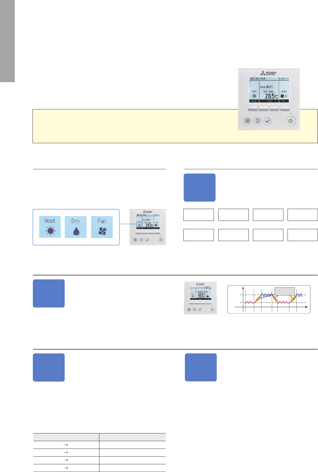
25
Energy-
Saving
Schedule
Busy
hours
5
■
Setting Example
(restaurant in summer time)
Display Example [Operation Mode]
Full Dot LCD
Multi-
Ianguage
26
25
24
23
22
0
10:00 12:00 14:00 16:00 18:00 20:00 22:00 24:00
Temperature setting (°C)
Opening
time
Lunch time
Preparation
Dinner time
8-patterns setting
Closing time
Set to lower temperatureSet to higher temperature
1
2
4
3
6
7
8
(Time)
Necessary to change temperature settings for cooling/heating times.
*Joint research conducted with Japan Facility Solutions, Inc.
■ Setting pattern example
CONTROL TECHNOLOGIES
User-friendly Deluxe Remote Controller with Excellent
Operability and Visibility
Full Dot Liquid-crystal Display Adopted
Easier to read thanks to use of a full dot liquid-crystal display
with backlight, and easier to use owing to adopting a menu
format that has reduced the number of operating buttons.
Operation Control Functions
Multi-language Display
Control panel operation in eight
different languages
Choose the desired language, among the
following languages.
Temperature Control
Two preset temperatures
When the operation mode is set to the Auto (dual
set point) mode, two preset temperatures (one
each for cooling and heating) can be set. Depend-
ing on the room temperature, indoor unit will
automatically operate in either the COOL or HEAT mode and keep
the room temperature within the preset range.
Precise control of power consumption
The amount of power consumed in each time period is managed so
that the demand value is not exceeded. The demand control func-
tion can be set to start and finish in 5-minute units. Additionally, the
level can be adjusted to 0, 50, 60, 70, 80 or 90% of maximum capac-
ity, and up to 4 patterns can be set per day. Air-conditioning opera-
tion is automatically controlled to ensure that electricity in excess of
the contracted volume is not consumed.
Auto-return
Prevents wasteful operation by automati-
cally returning to the preset temperature
after specified operating time
After adjusting the temperature for initial heating in winter or cool-
ing on a hot summer day, it is easy to forget to return the tempera-
ture setting to its original value. The Auto-return function automati-
cally resets the temperature back to the original setting after a spec-
ified period of time, thereby preventing overheating/overcooling.
The Auto-return activation time can be set in 10-minute units, in a
range between 30 and 120 minutes.
*Auto-return cannot be used when Temperature Range Restrictions is in use.
Easy To Read & Easy To Use
Energy-efficient Control
Temperature
Range
Restriction
Cooling/Dry
Office Restaurant
Recommended for
(Setting example of minimum temp. in 25°C)
Lower temperature limit
Possible temperature range setting
19(˚C) 30(˚C)
30(˚C)25(˚C)
To prevent excessive cooling
Lower temperatures cannot
be selected
Temperature Range Restriction prevents
overheating/overcooling
Using a temperature that is 1°C lower/higher for heating/cooling re-
sults in a 10% reduction in power consumption.* Temperature
Range Restriction limits the maximum and minimum temperature
settings, contributing to the prevention of overheating/overcooling.
*In-house calculations
Night
Setback
Keep desired room temperatures
automatically
This function monitors the room temperature and automatically acti-
vates the heating mode when the temperature drops below the
preset minimal temperature setting. It has the same function for
cooling, automatically activating the cooling mode when the tem-
perature rises above the preset maximum temperature setting.
Meeting room Changing room
Recommended for
Auto-off
Timer
Turns heating/cooling off automatically
after preset time elapses
When using Auto-off Timer, even if one forgets to turn off the unit,
operation stops automatically after the preset time elapses, thereby
preventing wasteful operation. Auto-off Timer can be set in 10-
minute units, in a range between 30 minutes and 4 hours. Elimi-
nates all anxiety about forgetting to turn off the unit.
Weekly
Timer
Set up to 8 patterns per day including temperature control
The Weekly Timer enables the setting of operation start and finish times and adjusting the temperature as standard features. Up to 8 patterns per
day can be set, providing operation that matches the varying conditions of each period, such as the number of customers in the store.
*Weekly Timer cannot be used when On/Off Timer is in use.
Computer server facility
Recommended for
Office
School
Hospital
Public hall
Operation
Lock
Fixed temperature setting promotes
energy savings
In addition to operation start/stop, the operation mode, temperature
setting and airflow direction can be locked. Unwanted adjustment
of temperature settings is prevented and an appropriate tempera-
ture is constantly maintained, leading to energy savings. This fea-
ture is also useful in preventing erroneous operation or tampering.
PAR-32MAA
Off-peak
hours
Start time
8:15
12:00
13:00
17:00
Finish time
12:00
13:00
17:00
21:00
Capacity savings
80%
50%
90%
50%
Dual
set point
*Please refer to the function list on pages 23-24 for the combination of
the available units.
Operation pattern during Auto (dual set point) mode
Preset temp.
(COOL)
Preset temp.
(HEAT)
Room
temperature
HEAT HEATCOOL COOL
The room temperature
changes corresponding
to the change in the
outside temperature.
English Spanish Italian Turkish
French Greek Portuguese Swedish
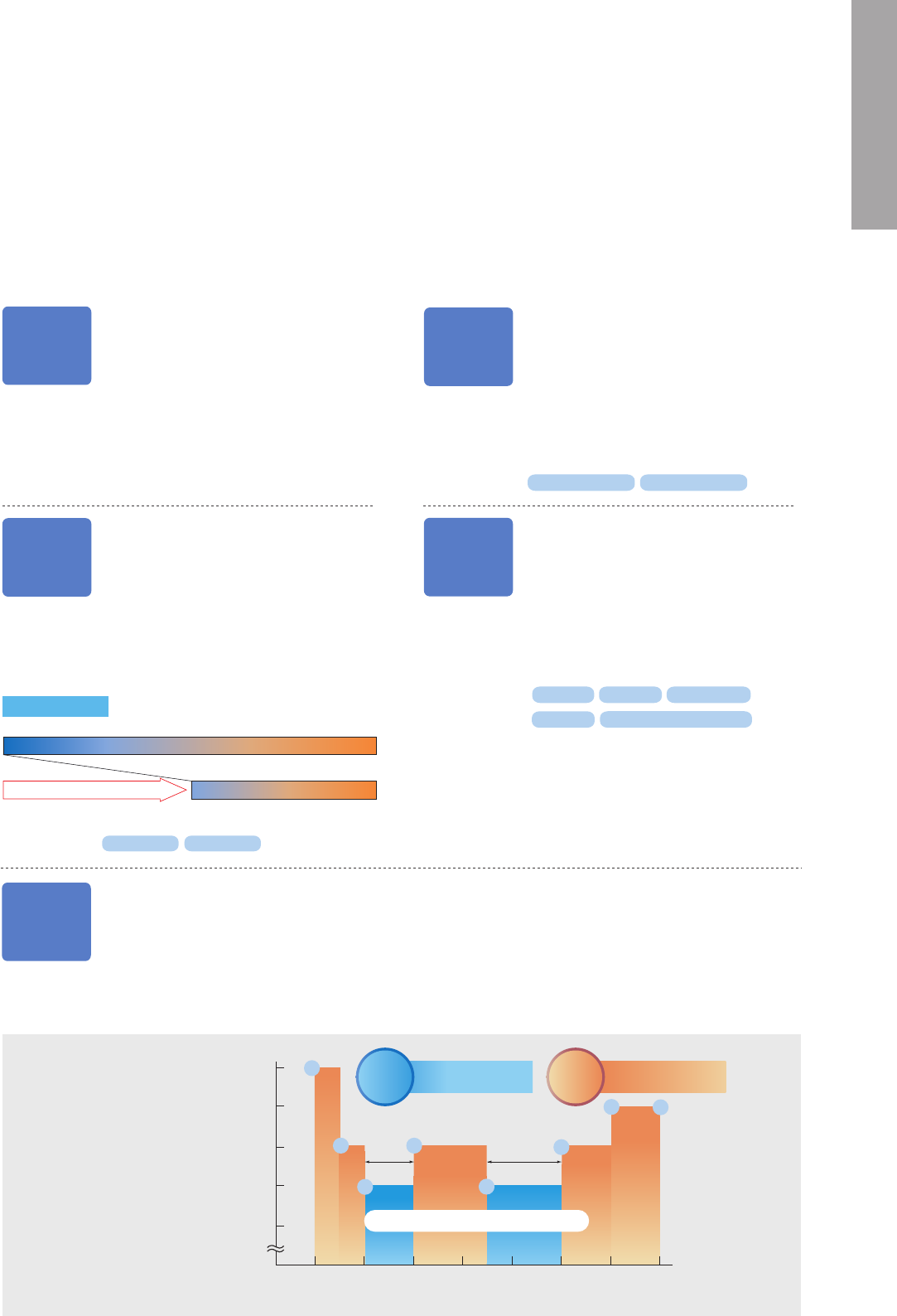
26
Energy-
Saving
Schedule
Busy
hours
5
■
Setting Example
(restaurant in summer time)
Display Example [Operation Mode]
Full Dot LCD
Multi-
Ianguage
26
25
24
23
22
0
10:00 12:00 14:00 16:00 18:00 20:00 22:00 24:00
Temperature setting (°C)
Opening
time
Lunch time
Preparation
Dinner time
8-patterns setting
Closing time
Set to lower temperatureSet to higher temperature
1
2
4
3
6
7
8
(Time)
Necessary to change temperature settings for cooling/heating times.
*Joint research conducted with Japan Facility Solutions, Inc.
■ Setting pattern example
CONTROL TECHNOLOGIES
User-friendly Deluxe Remote Controller with Excellent
Operability and Visibility
Full Dot Liquid-crystal Display Adopted
Easier to read thanks to use of a full dot liquid-crystal display
with backlight, and easier to use owing to adopting a menu
format that has reduced the number of operating buttons.
Operation Control Functions
Multi-language Display
Control panel operation in eight
different languages
Choose the desired language, among the
following languages.
Temperature Control
Two preset temperatures
When the operation mode is set to the Auto (dual
set point) mode, two preset temperatures (one
each for cooling and heating) can be set. Depend-
ing on the room temperature, indoor unit will
automatically operate in either the COOL or HEAT mode and keep
the room temperature within the preset range.
Precise control of power consumption
The amount of power consumed in each time period is managed so
that the demand value is not exceeded. The demand control func-
tion can be set to start and finish in 5-minute units. Additionally, the
level can be adjusted to 0, 50, 60, 70, 80 or 90% of maximum capac-
ity, and up to 4 patterns can be set per day. Air-conditioning opera-
tion is automatically controlled to ensure that electricity in excess of
the contracted volume is not consumed.
Auto-return
Prevents wasteful operation by automati-
cally returning to the preset temperature
after specified operating time
After adjusting the temperature for initial heating in winter or cool-
ing on a hot summer day, it is easy to forget to return the tempera-
ture setting to its original value. The Auto-return function automati-
cally resets the temperature back to the original setting after a spec-
ified period of time, thereby preventing overheating/overcooling.
The Auto-return activation time can be set in 10-minute units, in a
range between 30 and 120 minutes.
*Auto-return cannot be used when Temperature Range Restrictions is in use.
Easy To Read & Easy To Use
Energy-efficient Control
Temperature
Range
Restriction
Cooling/Dry
Office Restaurant
Recommended for
(Setting example of minimum temp. in 25°C)
Lower temperature limit
Possible temperature range setting
19(˚C) 30(˚C)
30(˚C)25(˚C)
To prevent excessive cooling
Lower temperatures cannot
be selected
Temperature Range Restriction prevents
overheating/overcooling
Using a temperature that is 1°C lower/higher for heating/cooling re-
sults in a 10% reduction in power consumption.* Temperature
Range Restriction limits the maximum and minimum temperature
settings, contributing to the prevention of overheating/overcooling.
*In-house calculations
Night
Setback
Keep desired room temperatures
automatically
This function monitors the room temperature and automatically acti-
vates the heating mode when the temperature drops below the
preset minimal temperature setting. It has the same function for
cooling, automatically activating the cooling mode when the tem-
perature rises above the preset maximum temperature setting.
Meeting room Changing room
Recommended for
Auto-off
Timer
Turns heating/cooling off automatically
after preset time elapses
When using Auto-off Timer, even if one forgets to turn off the unit,
operation stops automatically after the preset time elapses, thereby
preventing wasteful operation. Auto-off Timer can be set in 10-
minute units, in a range between 30 minutes and 4 hours. Elimi-
nates all anxiety about forgetting to turn off the unit.
Weekly
Timer
Set up to 8 patterns per day including temperature control
The Weekly Timer enables the setting of operation start and finish times and adjusting the temperature as standard features. Up to 8 patterns per
day can be set, providing operation that matches the varying conditions of each period, such as the number of customers in the store.
*Weekly Timer cannot be used when On/Off Timer is in use.
Computer server facility
Recommended for
Office
School
Hospital
Public hall
Operation
Lock
Fixed temperature setting promotes
energy savings
In addition to operation start/stop, the operation mode, temperature
setting and airflow direction can be locked. Unwanted adjustment
of temperature settings is prevented and an appropriate tempera-
ture is constantly maintained, leading to energy savings. This fea-
ture is also useful in preventing erroneous operation or tampering.
PAR-32MAA
Off-peak
hours
Start time
8:15
12:00
13:00
17:00
Finish time
12:00
13:00
17:00
21:00
Capacity savings
80%
50%
90%
50%
Dual
set point
*Please refer to the function list on pages 23-24 for the combination of
the available units.
Operation pattern during Auto (dual set point) mode
Preset temp.
(COOL)
Preset temp.
(HEAT)
Room
temperature
HEAT HEATCOOL COOL
The room temperature
changes corresponding
to the change in the
outside temperature.
English Spanish Italian Turkish
French Greek Portuguese Swedish
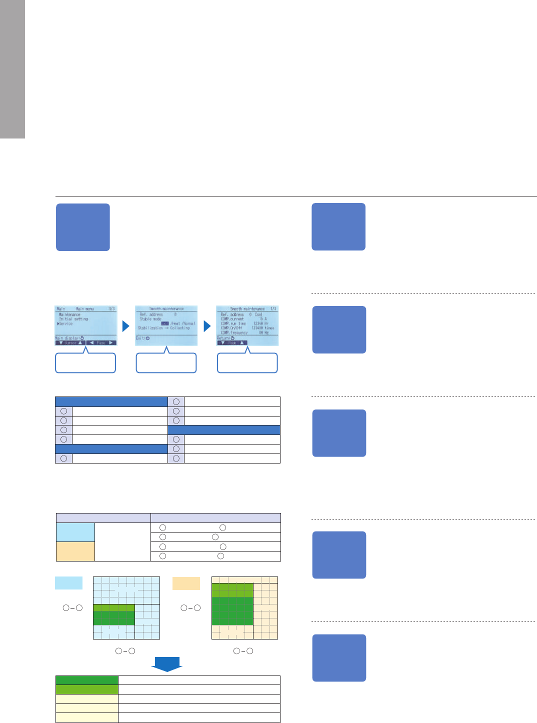
27
Simple MA Remote Controller
PAC-YT52CRA
CONTROL TECHNOLOGIES
Backlit LCD
Features a liquid-crystal display (LCD) with backlight for
operation in dark conditions.
Flat Back
The slim and flat-back shape makes installation easier without
requiring a hole in the wall. Thickness is 14.5mm or less.
Vane Angle Setting
Installation/Maintenance Support Functions
Smooth
Maintenance
Outdoor unit data accessed immediately,
enabling fast maintenance
(only PUHZ type)
Using the Stable Operation Control (fixed frequency) of the Smooth
Maintenance function, the operating status of the inverter can be
checked easily via the screen on the remote controller.
✽
1:
Due to indoor and outdoor temperatures, “Filter inspection” may be displayed even if the filter is
not blocked.
✽
The above graphs are based on trial data. Results may vary depending on installation/temperature
conditions.
●
Stable operation may not be possible under the following temperature conditions:
a) In cooling mode when the outdoor induction temperature is over 40°C or the indoor induction
temperature is below 23°C.
b) In heating mode when the outdoor induction temperature is over 20°C or when the indoor
induction temperature is over 25°C.
●
If the above temperature conditions do not apply and stable operation is not achieved after 30
minutes has passed, please inspect the units.
●
The operating status may change due to frost on the outdoor heat exchanger.
Manual
Vane Angle
Setting
Direction of vertical airflow for each
vane can be set
Setting the vertical airflow direction for each individual vane can be
performed simply via illustrated display. Seasonal settings such as
switching between cooling and heating are easily changed as well.
Three outdoor noise level setting
(4-way ceiling
cassette)
Auto-
descending
Panel
Operation
Easily raise/lower panels using the
remote controller
Auto-descending panel operation is available as an option. Panels
can be raise/lower using a button on the wired remote controller.
Filter cleaning can be performed easily.
Refrigerant
Leakage
Check
Easily check refrigerant leakage
The Mr. Slim Power Inverter units come equipped with a useful
“Refrigerant Leakage Check” function. Using a wired remote con-
troller, it is easy to check if refrigerant has been lost over a long
period of use. This reduces service time and gives an added sense
of safety.
Silent Mode
Initial
Password
Setting
Select the service
from menu
Activate Stable
Operation
Data is displayed
Inspection Guidelines
The computed temperature difference is plotted as in the graph below and
operating status is determined.
COMP. current (A)
COMP. run time (Hr)
COMP. ON/OFF (times)
COMP. frequency (Hz)
Sub cool (°C)
OU TH7 temp. (°C)
IU air temp. (°C)
IU HEX temp. (°C)
IU filter operating time* (Hr)
2
9
1
8
OU TH6 temp. (°C)
7
OU TH4 temp. (°C)
6
3
10
6 7
4
11
5
40
45
35
30
25
20
15
10
5
0
10 20 30 40 50 60 70 80
(°C)
(°C)
40
45
35
30
25
20
15
10
5
0
10 20 30 40 50 60 70 80
(°C)
(°C)
Cooling
operation
Heating
operation
Normal
Filter inspection
Normal
Filter inspection
Inspection C
Inspection B
Inspection A
Inspection C
Inspection B
Inspection A
Result
■
Smooth Maintenance Function Operating Procedure
Display information (11 items)
*IU filter operating time is the time elapsed since filter was reset.
Compressor
Outdoor Unit
Indoor Unit
9
6
10
10
Temp. difference
Cooling
Heating
Item
( OU TH4 temp.) – ( OU TH6 temp.)
( IU air temp.) – ( IU HEX temp.)
( OU TH4 temp.) – ( IU HEX temp.)
( IU HEX temp.) – ( IU air temp.)
6 7
9 10
6 10
10 9
9
10
The outdoor noise level can be reduced on demand according to the
surrounding environment. Select from three setting mode: standard
mode (rated), silent mode and ultra-silent mode.
Password for initial settings
A password is required (default setting is “0000”) for initial settings
such as time and display language.
Normal
Filter inspection
Inspection A
Inspection B
Inspection C
Normal operating status.
Filter may be blocked.
✽
1
Capacity is reduced. Detailed inspection is necessary.
Refrigerant level is low.
Filter or indoor unit heat exchanger is blocked.
Rotation, Back-up and 2nd Stage Cut-in Functions (PAR-32MAA)
(1) Rotation and Back-up Functions
Function Outline
• Main and sub units take turns operating according
to a rotation interval setting.
• If one unit malfunctions, the other unit automati-
cally begins operation (Back-up function)
Operation Pattern
System Image
O/U : Outdoor unit
I/U : Indoor unit
R/C : Wired remote controller
Operation Pattern
[Back-up function only]
Start operation
Error occurs on main unit.
Main Sub
[Rotation function] & [Back-up function]
(Ex: When the request code is “313”, each unit operates alternately in daily cycle.)
Start operation
1–28 days 1–28 days
Main SubSub Main
Error occurs on main unit.
Main Sub
Main
unit
I/U-1
Sub
unit
I/U-2
Run
Stop
Abnormal condition
Run
Main
unit
I/U-1
Sub
unit
I/U-2
RunStopRun
Stop
Abnormal condition
RunStopRun
[2nd stage cut-in function]
Start operation
Room temp.
>
=
Set point
Sub unit starts operation
Room temp.
>
=
Set point –4°C
Sub unit stops
Main
unit
I/U-1
Sub
unit
I/U-2
Run
Stop RunStop
O/U-1 O/U-2
I/U-1
R/C
I/U-2
Sub
unit
Main
unit
(2) 2nd Stage Cut-in Function
Function Outline
• Number of units operating is based on room tem-
perature and predetermined settings.
• When room temperature rises above the desired
setting, the standby unit starts (2-unit operation).
• When the room temperature falls 4°C below the
predetermined setting, the standby unit stops (1-
unit operation).
System Constraint
• This function is only available for rotation operation
and when the back-up function is in cooling mode.
The vane button has been added to allow users to change the
airflow direction (ceiling-cassette and wall-mounted units).
Pressing the button will switch
the vane direction.
AUTO Setting 1 Setting 2Setting 3Setting 4Setting 5 Swing
* The settable vane directions vary depending on the indoor unit model to be connected.
* If the unit has no vane function, the vane direction cannot be set. In this case, the vane icon flashes when the button is pressed.
Flat
back
120mm
(4-23/32 in)
70mm (2-3/4 in)
Max
14.5mm (9/16 in)
*Please refer to the function list on pages 23-24 for the combination of
the available units.
Operation pattern during Auto (dual set point) mode
Preset temp.
(COOL)
Preset temp.
(HEAT)
Room
temperature
HEAT HEATCOOL COOL
The room temperature
changes corresponding
to the change in the
outside temperature.
Dual set point
Two preset temperatures
When the operation mode is set to the Auto (dual set point) mode, two preset
temperatures (one each for cooling and heating) can be set. Depending on
the room temperature, indoor unit will automatically operate in either the
COOL or HEAT mode and keep the room temperature within the preset range.
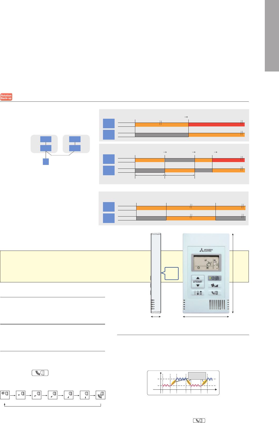
28
Simple MA Remote Controller
PAC-YT52CRA
CONTROL TECHNOLOGIES
Backlit LCD
Features a liquid-crystal display (LCD) with backlight for
operation in dark conditions.
Flat Back
The slim and flat-back shape makes installation easier without
requiring a hole in the wall. Thickness is 14.5mm or less.
Vane Angle Setting
Installation/Maintenance Support Functions
Smooth
Maintenance
Outdoor unit data accessed immediately,
enabling fast maintenance
(only PUHZ type)
Using the Stable Operation Control (fixed frequency) of the Smooth
Maintenance function, the operating status of the inverter can be
checked easily via the screen on the remote controller.
✽
1:
Due to indoor and outdoor temperatures, “Filter inspection” may be displayed even if the filter is
not blocked.
✽
The above graphs are based on trial data. Results may vary depending on installation/temperature
conditions.
●
Stable operation may not be possible under the following temperature conditions:
a) In cooling mode when the outdoor induction temperature is over 40°C or the indoor induction
temperature is below 23°C.
b) In heating mode when the outdoor induction temperature is over 20°C or when the indoor
induction temperature is over 25°C.
●
If the above temperature conditions do not apply and stable operation is not achieved after 30
minutes has passed, please inspect the units.
●
The operating status may change due to frost on the outdoor heat exchanger.
Manual
Vane Angle
Setting
Direction of vertical airflow for each
vane can be set
Setting the vertical airflow direction for each individual vane can be
performed simply via illustrated display. Seasonal settings such as
switching between cooling and heating are easily changed as well.
Three outdoor noise level setting
(4-way ceiling
cassette)
Auto-
descending
Panel
Operation
Easily raise/lower panels using the
remote controller
Auto-descending panel operation is available as an option. Panels
can be raise/lower using a button on the wired remote controller.
Filter cleaning can be performed easily.
Refrigerant
Leakage
Check
Easily check refrigerant leakage
The Mr. Slim Power Inverter units come equipped with a useful
“Refrigerant Leakage Check” function. Using a wired remote con-
troller, it is easy to check if refrigerant has been lost over a long
period of use. This reduces service time and gives an added sense
of safety.
Silent Mode
Initial
Password
Setting
Select the service
from menu
Activate Stable
Operation
Data is displayed
Inspection Guidelines
The computed temperature difference is plotted as in the graph below and
operating status is determined.
COMP. current (A)
COMP. run time (Hr)
COMP. ON/OFF (times)
COMP. frequency (Hz)
Sub cool (°C)
OU TH7 temp. (°C)
IU air temp. (°C)
IU HEX temp. (°C)
IU filter operating time* (Hr)
2
9
1
8
OU TH6 temp. (°C)
7
OU TH4 temp. (°C)
6
3
10
6 7
4
11
5
40
45
35
30
25
20
15
10
5
0
10 20 30 40 50 60 70 80
(°C)
(°C)
40
45
35
30
25
20
15
10
5
0
10 20 30 40 50 60 70 80
(°C)
(°C)
Cooling
operation
Heating
operation
Normal
Filter inspection
Normal
Filter inspection
Inspection C
Inspection B
Inspection A
Inspection C
Inspection B
Inspection A
Result
■
Smooth Maintenance Function Operating Procedure
Display information (11 items)
*IU filter operating time is the time elapsed since filter was reset.
Compressor
Outdoor Unit
Indoor Unit
9
6
10
10
Temp. difference
Cooling
Heating
Item
( OU TH4 temp.) – ( OU TH6 temp.)
( IU air temp.) – ( IU HEX temp.)
( OU TH4 temp.) – ( IU HEX temp.)
( IU HEX temp.) – ( IU air temp.)
6 7
9 10
6 10
10 9
9
10
The outdoor noise level can be reduced on demand according to the
surrounding environment. Select from three setting mode: standard
mode (rated), silent mode and ultra-silent mode.
Password for initial settings
A password is required (default setting is “0000”) for initial settings
such as time and display language.
Normal
Filter inspection
Inspection A
Inspection B
Inspection C
Normal operating status.
Filter may be blocked.
✽
1
Capacity is reduced. Detailed inspection is necessary.
Refrigerant level is low.
Filter or indoor unit heat exchanger is blocked.
Rotation, Back-up and 2nd Stage Cut-in Functions (PAR-32MAA)
(1) Rotation and Back-up Functions
Function Outline
• Main and sub units take turns operating according
to a rotation interval setting.
• If one unit malfunctions, the other unit automati-
cally begins operation (Back-up function)
Operation Pattern
System Image
O/U : Outdoor unit
I/U : Indoor unit
R/C : Wired remote controller
Operation Pattern
[Back-up function only]
Start operation
Error occurs on main unit.
Main Sub
[Rotation function] & [Back-up function]
(Ex: When the request code is “313”, each unit operates alternately in daily cycle.)
Start operation
1–28 days 1–28 days
Main SubSub Main
Error occurs on main unit.
Main Sub
Main
unit
I/U-1
Sub
unit
I/U-2
Run
Stop
Abnormal condition
Run
Main
unit
I/U-1
Sub
unit
I/U-2
RunStopRun
Stop
Abnormal condition
RunStopRun
[2nd stage cut-in function]
Start operation
Room temp.
>
=
Set point
Sub unit starts operation
Room temp.
>
=
Set point –4°C
Sub unit stops
Main
unit
I/U-1
Sub
unit
I/U-2
Run
Stop RunStop
O/U-1 O/U-2
I/U-1
R/C
I/U-2
Sub
unit
Main
unit
(2) 2nd Stage Cut-in Function
Function Outline
• Number of units operating is based on room tem-
perature and predetermined settings.
• When room temperature rises above the desired
setting, the standby unit starts (2-unit operation).
• When the room temperature falls 4°C below the
predetermined setting, the standby unit stops (1-
unit operation).
System Constraint
• This function is only available for rotation operation
and when the back-up function is in cooling mode.
The vane button has been added to allow users to change the
airflow direction (ceiling-cassette and wall-mounted units).
Pressing the button will switch
the vane direction.
AUTO Setting 1 Setting 2Setting 3Setting 4Setting 5 Swing
* The settable vane directions vary depending on the indoor unit model to be connected.
* If the unit has no vane function, the vane direction cannot be set. In this case, the vane icon flashes when the button is pressed.
Flat
back
120mm
(4-23/32 in)
70mm (2-3/4 in)
Max
14.5mm (9/16 in)
*Please refer to the function list on pages 23-24 for the combination of
the available units.
Operation pattern during Auto (dual set point) mode
Preset temp.
(COOL)
Preset temp.
(HEAT)
Room
temperature
HEAT HEATCOOL COOL
The room temperature
changes corresponding
to the change in the
outside temperature.
Dual set point
Two preset temperatures
When the operation mode is set to the Auto (dual set point) mode, two preset
temperatures (one each for cooling and heating) can be set. Depending on
the room temperature, indoor unit will automatically operate in either the
COOL or HEAT mode and keep the room temperature within the preset range.
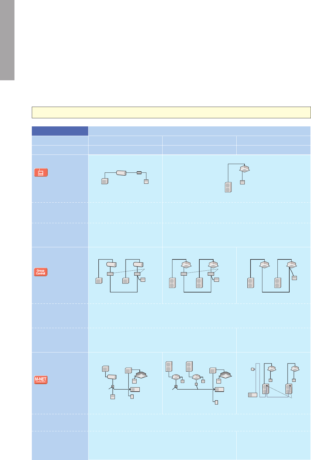
29
SYSTEM CONTROL
Versatile system controls can be realised using optional parts, relay circuits, control panels, etc.
MAJOR SYSTEM CONTROL
OTHERS
2-remote Controller
Control
With two remote controllers, control
can be performed locally and
remotely from two locations.
Operation Control by
Level Signal
Air conditioner can be started/
stopped remotely. In addition,
On/Off operation by local remote
controller can be prohibited/permitted.
Operation Control by
Pulse Signal
Remote Display of
Operating Status
Operating status can be
displayed at a remote location.
Allows On/Off operation with
timer
*For control by an external
timer, refer to B Operation
Control by Level Signal.
Timer Operation
PAR-32MAA
PAC-YT52CRA
PAR-32MAA
PAC-YT52CRA
(Example of 1 : 1 system)
(Example of 1 : 1 system)
Relay box (to be purchased) locally)
Relay box (to be purchased) locally)
Adapter for
remote
On/Off
Adapter for
remote
On/Off
PAR-SL97A-E
PAR-SL97A-E
(Example of 1 : 1 system)
PAR-32MAA
(Example of 1 : 1 system x 2)
Relay box (to be purchased locally)
(Example of 1 : 1 system x 2)
* Set "Main" and "Sub"
remote controllers.
* When using wired and
wireless remote controllers
PAR-SL97A-E
(Example of Simultaneous Twin)
(Example of Simultaneous Twin)
• Wired Remote Controller
PAR-32MAA
PAC-YT52CRA
(for PKA, PAC-SH29TC-E is required)
• Wireless Remote Controller
PAR-SL97A-E (Except for SLZ)
• Wireless Remote Controller Kit for PCA
PAR-SL99B-E
• Adapter for remote On/Off
PAC-SE55RA-E
• Relay box (to be purchased locally)
• Remote control panel (to be purchased
locally)
Standard functions of
PAR-32MAA
A
B
C
D
E
Details
Major Optional Parts Required
System Examples
Wired remote controller Wireless remote controller
Remote
display
panel
Remote
display
panel
PAR-32MAA/PAC-YT52CRA
Remote
control
panel
Remote
control
panelWired remote
controller
• Up to two remote controllers can be
connected to one group.
• Both wired and wireless remote controllers
can be used in combination.
• Operation other than On/Off (e.g., adjust-
ment of temperature, fan speed, and airflow)
can be performed even when remote
controller operation is prohibited.
• Timer control is possible with an external
timer.
Connector
cable for
remote
display
Connector
cable for
remote
display
PAR-SL97A-E
(Example of 1 : 1 system x 2)
Relay box (to be purchased locally)
(Example of 1 : 1 system x 2)
• Connector cable for remote display
PAC-SA88HA-E/PAC-725AD
(10 pcs. x PAC-SA88HA-E)
• Relay box (to be purchased locally)
• Remote control panel (to be purchased
locally)
Remote
control
panel
Remote
control
panelWired remote
controller
• The pulse signal can be turned On/Off.
• Operation/emergency signal can be
received at a remote location.
• Operation/emergency signal can be
received at a remote location (when
channeled through the PAC-SF40RM-E
no-voltage signal, when channeled through
the PAC-SA88HA-E DC 12V signal).
• Weekly Timer:
On/Off and up to 8 pattern temperatures can
be set for each calendar day. (Initial setting)
• On/Off Timer:
On/Off can be set once each within 72 hr in
intervals of 5-minute units.
• Auto-off Timer:
Operation will be switched off after a certain
time elapse. Set time can be changed from
30 min. to 4 hr. at 10 min. intervals.
*Simple Timer and Auto-off Timer
cannot be used at the same time.
• Remote display panel (to be purchased
locally)
• Connector cable for remote display
PAC-SA88HA-E/PAC-725AD
(10 pcs. x PAC-SA88HA-E)
• Relay box (to be purchased locally)
• Remote operation adapter
PAC-SF40RM-E
*Unable to use with wireless remote controller
Remote operation adapter/
Connector cable for remote display +
Relay box
Remote operation adapter/
Connector cable for remote display +
Relay box
For P Series and S Series Indoor Units
For M Series Indoor Units (New A-control Models Only)
1
2
Remote On/Off
Operation
Remote Display of
Operation Status
Control Details Major Optional Parts RequiredSystem Examples Connection Details
• MAC-333IF-E or MAC-397IF-E
(Interface)
• Parts for circuit such as relay
box, lead wire, etc. (to be
purchased locally)
• MAC-333IF-E or MAC-397IF-E
(Interface)
• Parts for circuit to be
purchased locally (DC power
source needed)
• External power source (12V DC)
is required when using
MAC-333IF-E.
Connect the interface to the air
conditioner. Then connect the
locally purchased remote controller
to the terminal in the interface.
Connect the interface to the air
conditioner. Then connect the
locally purchased remote controller
to the terminal in the interface.
On/Off operation is possible from
a remote location.
The operation status
(On/Off) or error signals can be
monitored from a remote location.
Outdoor unit
Indoor unit
MAC-333IF-E
MAC-397IF-E
Remote control section
(to be purchased locally)
Switch
Outdoor unit
Indoor unit
MAC-333IF-E
MAC-397IF-E
Remote monitor section
(to be purchased locally)
Power supply
Resistance
LED
• Air conditioner can be started/
stopped remotely.
( 1 and 2 can be used in
combination)
• The On/Off status of air
conditioners can be confirmed
remotely.
( 1 and 2 can be used in
combination)
M Series Indoor Unit
M Series and MXZ Series Outdoor
Indoor Unit
Outdoor Unit
S Series & P Series Indoor Unit
System Examples
S Series and MXZ Series Outdoor
P Series Indoor Unit
P Series Outdoor
Details
Major Optional Parts Required
• Group of air conditioners can be controlled by MELANS system controller (M-NET).
• MAC-333IF-E (M-NET Interface)
• MELANS System controller
• PAC-SC51KUA (power supply unit)
• PAC-SF83MA-E or PAC-SJ19MA-E
(M-NET converter)
• MELANS System controller
• PAC-SC51KUA (power supply unit)
Details
Major Optional Parts Required
• Wired remote controller can be connected to
indoor unit
• MAC-333IF-E or MAC-397IF-E (Interface)
• PAR-32MAA (Wired remote controller)
• PAC-YT52CRA (Wired remote controller)
• PAR-32MAA (Wired remote controller)
• PAC-YT52CRA (Wired remote controller)
Standard equipment (for indoor units compatible with wired remote controllers)
Details
Major Optional Parts Required
• One remote controller can control plural air conditioners with the same settings simultaneously.
• One remote controller can control up to 16 refrigerant systems.
(When connected to a MXZ unit, MAC-333IF-E or MAC-397IF-E is counted as one system.)
• Up to two remote controller can be connected.
• MAC-333IF-E or MAC-397IF-E (Interface)
• PAR-32MAA (Wired remote controller)
• PAC-YT52CRA (Wired remote controller)
• PAR-32MAA (Wired remote controller)
• PAC-YT52CRA (Wired remote controller)
Outdoor unit
Outdoor unit
Outdoor unit
Indoor unit
MAC-333IF-E
ME remote controller
(PAR-F27MEA)
PAC-SC51KUA
Power supply
unit
City Multi
indoor unit
PAR-32MAA
PAC-YT52CRA
MAC-333IF-E
MAC-397IF-E
PAR-32MAA
PAC-YT52CRA
PAR-32MAA Control
PAC-YT52CRA Control
System Group Control
M-NET Connections
PAR-32MAA
PAC-YT52CRA
Outdoor
unit
Indoor unit
MAC-333IF-E
MELANS
system controller
(AG-150A etc)
MELANS
system controller
(AG-150A etc)
PAC-SC51KUA
Power supply
unit
City Multi
indoor unit
PAR-32MAA
PAC-YT52CRA
Outdoor
unit
Outdoor
unit
Outdoor
unit
Indoor unit
PAR-32MAA
PAC-YT52CRA
M-NET adapter
PAC-SF83MA-E
PAC-SJ19MA-E
MELANS
system controller
(AG-150A etc)
PAC-SC51KUA
Power supply
kit
PAR-32MAA
PAC-YT52CRA
PAR-32MAA
PAC-YT52CRA
Indoor unitIndoor unit
PAR-32MAA
PAC-YT52CRA
MAC-333IF-E
MAC-397IF-E
Indoor unit
Outdoor unit
Indoor unit
Outdoor unit
Outdoor unit
Outdoor unit
Outdoor unit Outdoor unit Outdoor unit Outdoor unit
Indoor unit
Indoor unit
Indoor unit Indoor unit Indoor unit Indoor unit
MAC-333IF-E
MAC-397IF-E
PAR-32MAA
PAC-YT52CRA
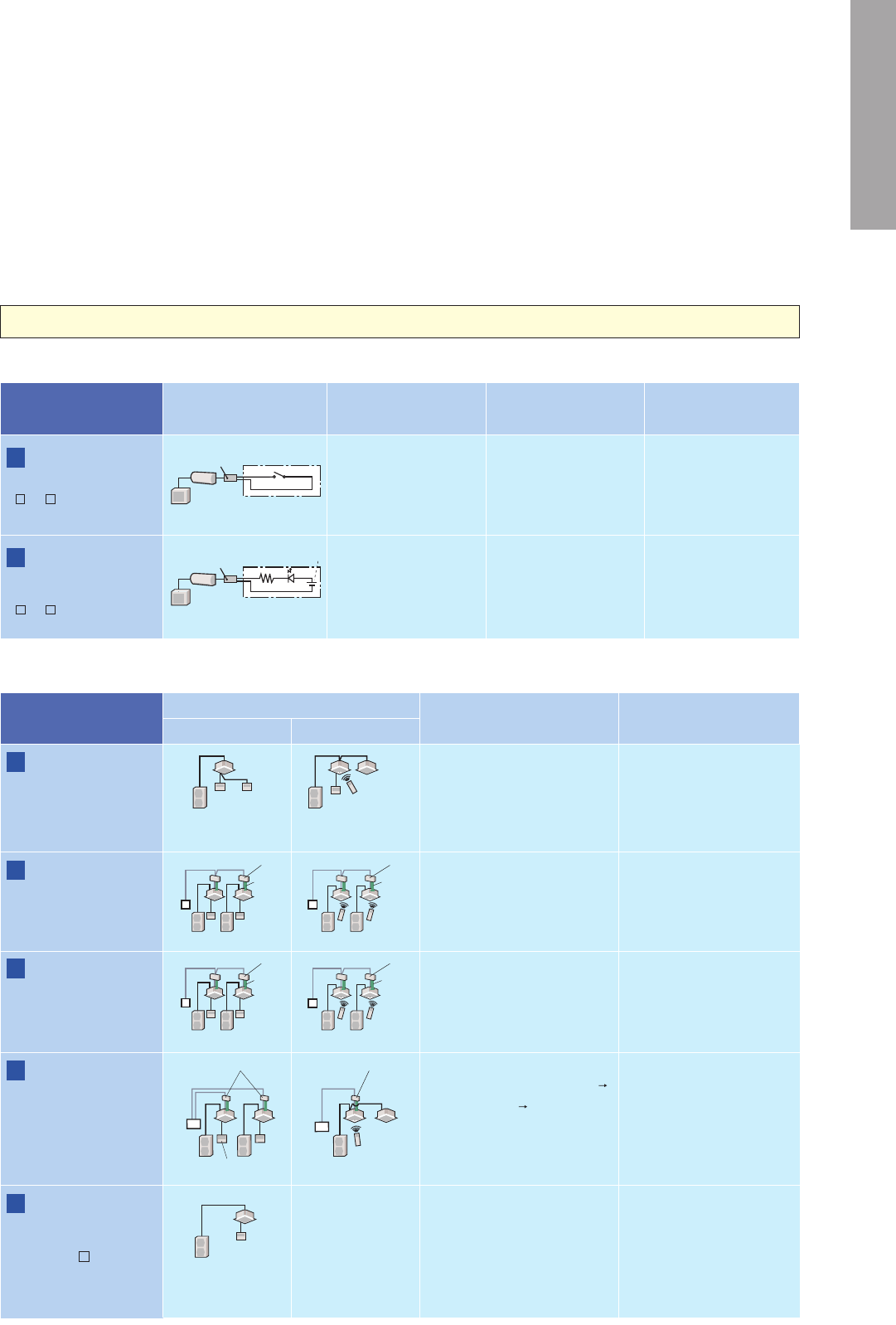
30
SYSTEM CONTROL
Versatile system controls can be realised using optional parts, relay circuits, control panels, etc.
MAJOR SYSTEM CONTROL
OTHERS
2-remote Controller
Control
With two remote controllers, control
can be performed locally and
remotely from two locations.
Operation Control by
Level Signal
Air conditioner can be started/
stopped remotely. In addition,
On/Off operation by local remote
controller can be prohibited/permitted.
Operation Control by
Pulse Signal
Remote Display of
Operating Status
Operating status can be
displayed at a remote location.
Allows On/Off operation with
timer
*For control by an external
timer, refer to B Operation
Control by Level Signal.
Timer Operation
PAR-32MAA
PAC-YT52CRA
PAR-32MAA
PAC-YT52CRA
(Example of 1 : 1 system)
(Example of 1 : 1 system)
Relay box (to be purchased) locally)
Relay box (to be purchased) locally)
Adapter for
remote
On/Off
Adapter for
remote
On/Off
PAR-SL97A-E
PAR-SL97A-E
(Example of 1 : 1 system)
PAR-32MAA
(Example of 1 : 1 system x 2)
Relay box (to be purchased locally)
(Example of 1 : 1 system x 2)
* Set "Main" and "Sub"
remote controllers.
* When using wired and
wireless remote controllers
PAR-SL97A-E
(Example of Simultaneous Twin)
(Example of Simultaneous Twin)
• Wired Remote Controller
PAR-32MAA
PAC-YT52CRA
(for PKA, PAC-SH29TC-E is required)
• Wireless Remote Controller
PAR-SL97A-E (Except for SLZ)
• Wireless Remote Controller Kit for PCA
PAR-SL99B-E
• Adapter for remote On/Off
PAC-SE55RA-E
• Relay box (to be purchased locally)
• Remote control panel (to be purchased
locally)
Standard functions of
PAR-32MAA
A
B
C
D
E
Details
Major Optional Parts Required
System Examples
Wired remote controller Wireless remote controller
Remote
display
panel
Remote
display
panel
PAR-32MAA/PAC-YT52CRA
Remote
control
panel
Remote
control
panelWired remote
controller
• Up to two remote controllers can be
connected to one group.
• Both wired and wireless remote controllers
can be used in combination.
• Operation other than On/Off (e.g., adjust-
ment of temperature, fan speed, and airflow)
can be performed even when remote
controller operation is prohibited.
• Timer control is possible with an external
timer.
Connector
cable for
remote
display
Connector
cable for
remote
display
PAR-SL97A-E
(Example of 1 : 1 system x 2)
Relay box (to be purchased locally)
(Example of 1 : 1 system x 2)
• Connector cable for remote display
PAC-SA88HA-E/PAC-725AD
(10 pcs. x PAC-SA88HA-E)
• Relay box (to be purchased locally)
• Remote control panel (to be purchased
locally)
Remote
control
panel
Remote
control
panelWired remote
controller
• The pulse signal can be turned On/Off.
• Operation/emergency signal can be
received at a remote location.
• Operation/emergency signal can be
received at a remote location (when
channeled through the PAC-SF40RM-E
no-voltage signal, when channeled through
the PAC-SA88HA-E DC 12V signal).
• Weekly Timer:
On/Off and up to 8 pattern temperatures can
be set for each calendar day. (Initial setting)
• On/Off Timer:
On/Off can be set once each within 72 hr in
intervals of 5-minute units.
• Auto-off Timer:
Operation will be switched off after a certain
time elapse. Set time can be changed from
30 min. to 4 hr. at 10 min. intervals.
*Simple Timer and Auto-off Timer
cannot be used at the same time.
• Remote display panel (to be purchased
locally)
• Connector cable for remote display
PAC-SA88HA-E/PAC-725AD
(10 pcs. x PAC-SA88HA-E)
• Relay box (to be purchased locally)
• Remote operation adapter
PAC-SF40RM-E
*Unable to use with wireless remote controller
Remote operation adapter/
Connector cable for remote display +
Relay box
Remote operation adapter/
Connector cable for remote display +
Relay box
For P Series and S Series Indoor Units
For M Series Indoor Units (New A-control Models Only)
1
2
Remote On/Off
Operation
Remote Display of
Operation Status
Control Details Major Optional Parts RequiredSystem Examples Connection Details
• MAC-333IF-E or MAC-397IF-E
(Interface)
• Parts for circuit such as relay
box, lead wire, etc. (to be
purchased locally)
• MAC-333IF-E or MAC-397IF-E
(Interface)
• Parts for circuit to be
purchased locally (DC power
source needed)
• External power source (12V DC)
is required when using
MAC-333IF-E.
Connect the interface to the air
conditioner. Then connect the
locally purchased remote controller
to the terminal in the interface.
Connect the interface to the air
conditioner. Then connect the
locally purchased remote controller
to the terminal in the interface.
On/Off operation is possible from
a remote location.
The operation status
(On/Off) or error signals can be
monitored from a remote location.
Outdoor unit
Indoor unit
MAC-333IF-E
MAC-397IF-E
Remote control section
(to be purchased locally)
Switch
Outdoor unit
Indoor unit
MAC-333IF-E
MAC-397IF-E
Remote monitor section
(to be purchased locally)
Power supply
Resistance
LED
• Air conditioner can be started/
stopped remotely.
( 1 and 2 can be used in
combination)
• The On/Off status of air
conditioners can be confirmed
remotely.
( 1 and 2 can be used in
combination)
M Series Indoor Unit
M Series and MXZ Series Outdoor
Indoor Unit
Outdoor Unit
S Series & P Series Indoor Unit
System Examples
S Series and MXZ Series Outdoor
P Series Indoor Unit
P Series Outdoor
Details
Major Optional Parts Required
• Group of air conditioners can be controlled by MELANS system controller (M-NET).
• MAC-333IF-E (M-NET Interface)
• MELANS System controller
• PAC-SC51KUA (power supply unit)
• PAC-SF83MA-E or PAC-SJ19MA-E
(M-NET converter)
• MELANS System controller
• PAC-SC51KUA (power supply unit)
Details
Major Optional Parts Required
• Wired remote controller can be connected to
indoor unit
• MAC-333IF-E or MAC-397IF-E (Interface)
• PAR-32MAA (Wired remote controller)
• PAC-YT52CRA (Wired remote controller)
• PAR-32MAA (Wired remote controller)
• PAC-YT52CRA (Wired remote controller)
Standard equipment (for indoor units compatible with wired remote controllers)
Details
Major Optional Parts Required
• One remote controller can control plural air conditioners with the same settings simultaneously.
• One remote controller can control up to 16 refrigerant systems.
(When connected to a MXZ unit, MAC-333IF-E or MAC-397IF-E is counted as one system.)
• Up to two remote controller can be connected.
• MAC-333IF-E or MAC-397IF-E (Interface)
• PAR-32MAA (Wired remote controller)
• PAC-YT52CRA (Wired remote controller)
• PAR-32MAA (Wired remote controller)
• PAC-YT52CRA (Wired remote controller)
Outdoor unit
Outdoor unit
Outdoor unit
Indoor unit
MAC-333IF-E
ME remote controller
(PAR-F27MEA)
PAC-SC51KUA
Power supply
unit
City Multi
indoor unit
PAR-32MAA
PAC-YT52CRA
MAC-333IF-E
MAC-397IF-E
PAR-32MAA
PAC-YT52CRA
PAR-32MAA Control
PAC-YT52CRA Control
System Group Control
M-NET Connections
PAR-32MAA
PAC-YT52CRA
Outdoor
unit
Indoor unit
MAC-333IF-E
MELANS
system controller
(AG-150A etc)
MELANS
system controller
(AG-150A etc)
PAC-SC51KUA
Power supply
unit
City Multi
indoor unit
PAR-32MAA
PAC-YT52CRA
Outdoor
unit
Outdoor
unit
Outdoor
unit
Indoor unit
PAR-32MAA
PAC-YT52CRA
M-NET adapter
PAC-SF83MA-E
PAC-SJ19MA-E
MELANS
system controller
(AG-150A etc)
PAC-SC51KUA
Power supply
kit
PAR-32MAA
PAC-YT52CRA
PAR-32MAA
PAC-YT52CRA
Indoor unitIndoor unit
PAR-32MAA
PAC-YT52CRA
MAC-333IF-E
MAC-397IF-E
Indoor unit
Outdoor unit
Indoor unit
Outdoor unit
Outdoor unit
Outdoor unit
Outdoor unit Outdoor unit Outdoor unit Outdoor unit
Indoor unit
Indoor unit
Indoor unit Indoor unit Indoor unit Indoor unit
MAC-333IF-E
MAC-397IF-E
PAR-32MAA
PAC-YT52CRA

SERIES
SELECTION
Choose the model that best matches room conditions.
SELECT OUTDOOR UNIT
Some outdoor units in the line-up have heaters for use in cold regions. Units with an “H” in the model name are equipped with heaters.
Heater Installed
Energy Rank
SEER
A
SCOP
A
Super energy-saving
Super
energy-
saving
Ultra-quiet operation
Ultra-quiet
Cooling and heating operation
Cooling
Heating
✽
To conrm compatibility with the MXZ Series multi-type system, refer to the MXZ Series page.
STEP 2
Selecting a Heater-equipped Model
In regions with the following conditions, there is a possibility that water resulting from condensation on the outdoor unit when operating in the heating mode
will freeze and not drain from the base.
1) Cold outdoor temperatures (temperature does not rise above 0
C all day)
2) Areas where dew forms easily (in the mountains, valleys(surrounded by mountains), near a forest, near unfrozen lakes, ponds, rivers or hot springs), or areas
with snowfall
To prevent water from freezing in the base, it is recommended that a unit with a built-in heater be purchased. Please ask your dealer representative about
the best
model for you.
MUZ-FH25/35VEHZ
MUZ-EF25/35VEH
MUZ-SF25/35/42VEH
MUFZ-KJ25/35VEHZ
MUZ-FH50VEHZ
MUZ-SF50VEH
MUFZ-KJ50VEHZ
Inverter
Compatible for connection to MXZ Series system
MSZ-F SERIES MSZ-E SERIES
MSZ-G SERIES
MFZ SERIES MLZ SERIES
MSZ-H SERIES
SELECT SERIESSTEP 1
Wall-mounted Units
A multiple series line-up to choose from, each with various outstanding features. In addition to inverter-equipped models, constant-speed,
oor-standing and cassette models can be selected. Choose the best series to match usage needs.
Cassette UnitsFloor-standing
✽
MXZ connection only
SEER
A
+++
SCOP
A
+++
SEER
A
++
SCOP
A
+
25/3525/3525/35
25/35 25/35
Super
energy-
saving
Ultra-quiet
Cooling
Heating
Cooling
Heating
Cooling
Heating
Cooling
Heating
SEER
A
++
SCOP
A
+
SEER
A
+
SCOP
A
+
50/60/71 50/60/71
Cooling
Heating
Cooling
Heating
MSZ-S SERIES
SEER
A
+++
SCOP
A
++
Cooling
Heating
SEER
A
+++
25
SCOP
A
+
MSZ-HJ60/71
MSZ-HJ25/35/50
31
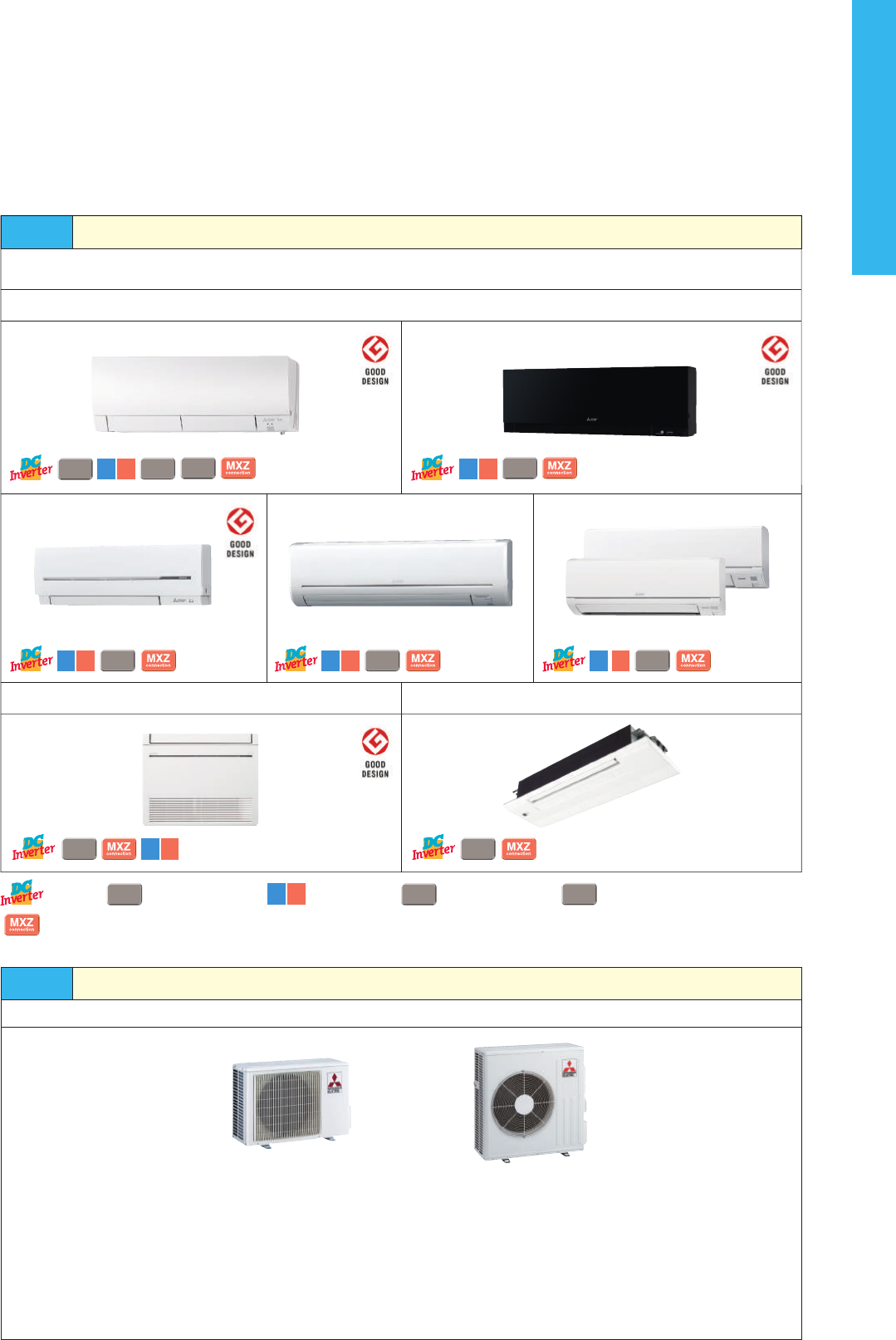
SERIES
SELECTION
Choose the model that best matches room conditions.
SELECT OUTDOOR UNIT
Some outdoor units in the line-up have heaters for use in cold regions. Units with an “H” in the model name are equipped with heaters.
Heater Installed
Energy Rank
SEER
A
SCOP
A
Super energy-saving
Super
energy-
saving
Ultra-quiet operation
Ultra-quiet
Cooling and heating operation
Cooling
Heating
✽
To conrm compatibility with the MXZ Series multi-type system, refer to the MXZ Series page.
STEP 2
Selecting a Heater-equipped Model
In regions with the following conditions, there is a possibility that water resulting from condensation on the outdoor unit when operating in the heating mode
will freeze and not drain from the base.
1) Cold outdoor temperatures (temperature does not rise above 0
C all day)
2) Areas where dew forms easily (in the mountains, valleys(surrounded by mountains), near a forest, near unfrozen lakes, ponds, rivers or hot springs), or areas
with snowfall
To prevent water from freezing in the base, it is recommended that a unit with a built-in heater be purchased. Please ask your dealer representative about
the best
model for you.
MUZ-FH25/35VEHZ
MUZ-EF25/35VEH
MUZ-SF25/35/42VEH
MUFZ-KJ25/35VEHZ
MUZ-FH50VEHZ
MUZ-SF50VEH
MUFZ-KJ50VEHZ
Inverter
Compatible for connection to MXZ Series system
MSZ-F SERIES MSZ-E SERIES
MSZ-G SERIES
MFZ SERIES MLZ SERIES
MSZ-H SERIES
SELECT SERIESSTEP 1
Wall-mounted Units
A multiple series line-up to choose from, each with various outstanding features. In addition to inverter-equipped models, constant-speed,
oor-standing and cassette models can be selected. Choose the best series to match usage needs.
Cassette UnitsFloor-standing
✽
MXZ connection only
SEER
A
+++
SCOP
A
+++
SEER
A
++
SCOP
A
+
25/3525/3525/35
25/35 25/35
Super
energy-
saving
Ultra-quiet
Cooling
Heating
Cooling
Heating
Cooling
Heating
Cooling
Heating
SEER
A
++
SCOP
A
+
SEER
A
+
SCOP
A
+
50/60/71 50/60/71
Cooling
Heating
Cooling
Heating
MSZ-S SERIES
SEER
A
+++
SCOP
A
++
Cooling
Heating
SEER
A
+++
25
SCOP
A
+
MSZ-HJ60/71
MSZ-HJ25/35/50
32

MSZ-F
SERIES
The F Series is designed for optimum cooling/heating performance as well as operational
comfort. Quiet, energy-saving operation is supported by some of Mitsubishi Electric’s latest
technologies. Advanced functions such as “3D i-see Sensor” temperature control and the
Plasma Quad air purication system raise room comfort levels to new heights.
SEER
A
+++
SCOP
A
+++
Cooling
Heating
SCOP
5.1
SEER
8.9
SCOP
5.1
MSZ-FH25VE MSZ-FH35VE
SEER
7.2
SCOP
4.6
MSZ-FH50VE
SEER
9.1
SEER Rank A(5.1)
SCOP Rank A(3.8)
High Energy Eciency
Power consumption has been reduced for the cooling and heating
modes thanks to the incorporation of our newest inverter technologies.
The high energy eciency of the Size 25 units has obtained a rating of
more than 5.0 for both seasonal coecient of performance (SCOP) and
seasonal energy eciency rating (SEER).
MSZ-FH25/35/50VE2
Hyper Heating
The Hyper Heating feature is incorporated, realizing powerful heating even in the harsh cold. Even users in cold regions can comfortably rely on
the MSZ-FH Series for all their heating needs.
MUZ-FH VEHZ can be operated at outside temperatures
as low as -25°C, so there are no concerns about use
even in very cold climates.
With rated capacity ensured at outside temperature as
low as -15°C, the FH Series can be relied upon to properly
warm living spaces even in severe cold snaps.
The Freeze-prevention heater prevents lowered capacity
due to the drain freezing and also inhibits operation
shutdowns.
Operation Guaranteed at
Outside Temperature of
-25°C
MUZ-FH25VEMUZ-FH25VEHZ MUZ-FH35VEMUZ-FH35VEHZ
2.5
kW
kW kW
kW
3.23.2
4.0
-25
o
C -20
o
C -15
o
C -10
o
C
MUZ-FH VEHZ
MUZ-FH VE
Rated Capacity Demonstrated at
Outside Temperatures of
-15°C
Freeze-prevention Heater
Equipped as Standard (VEHZ)
Without Freeze-prevention heater
Frozen drain
With Freeze-prevention heater
Drain does not freeze
Selecting a Heater-equipped Model
In regions with the following conditions, there is a possibility that water resulting from condensation on the outdoor unit when operating in the heating
mode will freeze and not drain from the base.
1) Cold outdoor temperatures (temperature does not rise above 0°C all day)
2) Areas where dew forms easily (in the mountains, valleys(surrounded by mountains), near a forest, near unfrozen lakes, ponds, rivers or hot springs), or areas
with snowfall
To prevent water from freezing in the base, it is recommended that a unit with a built-in heater be purchased. Please ask your dealer representative about the
best model for you.
Air, like water, is something we use everyday unconsciously. Yet, clean, fresh air is a vital part of creating a healthy space for humans. Achieving this
healthy air is Plasma Quad, a plasma-based lter system that eectively removes four kinds of air pollutants; namely, bacteria, viruses, allergens and
dust, which the air contains countless particles of.
Principle of Plasma Quad
Plasma Quad attacks bacteria and viruses from inside the unit using a strong curtain-like electrical
eld and discharge of electric current across the whole inlet-air opening of the unit. Tungsten
discharge electrodes are used as they provide both discharge capacity and strength. In addition,
through attening the standard, round form of the eld to a ribbon-like shape, a strong electrical
eld is produced.
[ Eective Range ]
MacroNanoParticulate size
Plasma Quad Air-purifying lter
Viruses
Pollen Bacteria
Fish odours
Pet odours
Mold spores
Rubbish odours
Dust VirusesAllergens Bad Odours
Allergens
In a test, air containing cat fur and pollen was
passed through the air cleaning device at the low
airow setting. Before and after measurements
conrm that Plasma Quad neutralizes 94% of cat fur
and 98% of pollen.
Viruses
Without Plasma QuadWith Plasma Quad
Test results have conrmed that Plasma Quad
neutralizes 99% of virus particles in 65 minutes in
a 25m
3
test space.
* Hepatic cells turn transparent when affected by a virus.
Round:
Flattened: a strong electrical field is produced.
Air
Virus
Bacteria
Dust
Air
Neutralization/inactivation
Plasma
field
Bacteria
Test results have conrmed that Plasma Quad
neutralizes 99% of bacteria in 115 minutes in a
25m
3
test space.
Plasma Quad oPlasma Quad on
Dust
In a test, air containing dust and ticks was passed
through the air cleaning device at the low airow
setting. Before and after measurements conrm
that Plasma Quad removes 88.6% of dust and ticks.
Eective deodorizing using
the air-purifying lter
(Image)
25/35 25/35
33
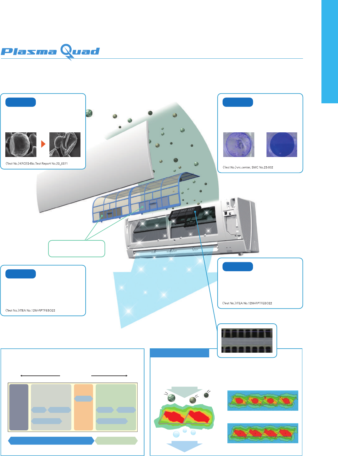
MSZ-F
SERIES
The F Series is designed for optimum cooling/heating performance as well as operational
comfort. Quiet, energy-saving operation is supported by some of Mitsubishi Electric’s latest
technologies. Advanced functions such as “3D i-see Sensor” temperature control and the
Plasma Quad air purication system raise room comfort levels to new heights.
SEER
A
+++
SCOP
A
+++
Cooling
Heating
SCOP
5.1
SEER
8.9
SCOP
5.1
MSZ-FH25VE MSZ-FH35VE
SEER
7.2
SCOP
4.6
MSZ-FH50VE
SEER
9.1
SEER Rank A(5.1)
SCOP Rank A(3.8)
High Energy Eciency
Power consumption has been reduced for the cooling and heating
modes thanks to the incorporation of our newest inverter technologies.
The high energy eciency of the Size 25 units has obtained a rating of
more than 5.0 for both seasonal coecient of performance (SCOP) and
seasonal energy eciency rating (SEER).
MSZ-FH25/35/50VE2
Hyper Heating
The Hyper Heating feature is incorporated, realizing powerful heating even in the harsh cold. Even users in cold regions can comfortably rely on
the MSZ-FH Series for all their heating needs.
MUZ-FH VEHZ can be operated at outside temperatures
as low as -25°C, so there are no concerns about use
even in very cold climates.
With rated capacity ensured at outside temperature as
low as -15°C, the FH Series can be relied upon to properly
warm living spaces even in severe cold snaps.
The Freeze-prevention heater prevents lowered capacity
due to the drain freezing and also inhibits operation
shutdowns.
Operation Guaranteed at
Outside Temperature of
-25°C
MUZ-FH25VEMUZ-FH25VEHZ MUZ-FH35VEMUZ-FH35VEHZ
2.5
kW
kW kW
kW
3.23.2
4.0
-25
o
C -20
o
C -15
o
C -10
o
C
MUZ-FH VEHZ
MUZ-FH VE
Rated Capacity Demonstrated at
Outside Temperatures of
-15°C
Freeze-prevention Heater
Equipped as Standard (VEHZ)
Without Freeze-prevention heater
Frozen drain
With Freeze-prevention heater
Drain does not freeze
Selecting a Heater-equipped Model
In regions with the following conditions, there is a possibility that water resulting from condensation on the outdoor unit when operating in the heating
mode will freeze and not drain from the base.
1) Cold outdoor temperatures (temperature does not rise above 0°C all day)
2) Areas where dew forms easily (in the mountains, valleys(surrounded by mountains), near a forest, near unfrozen lakes, ponds, rivers or hot springs), or areas
with snowfall
To prevent water from freezing in the base, it is recommended that a unit with a built-in heater be purchased. Please ask your dealer representative about the
best model for you.
Air, like water, is something we use everyday unconsciously. Yet, clean, fresh air is a vital part of creating a healthy space for humans. Achieving this
healthy air is Plasma Quad, a plasma-based lter system that eectively removes four kinds of air pollutants; namely, bacteria, viruses, allergens and
dust, which the air contains countless particles of.
Principle of Plasma Quad
Plasma Quad attacks bacteria and viruses from inside the unit using a strong curtain-like electrical
eld and discharge of electric current across the whole inlet-air opening of the unit. Tungsten
discharge electrodes are used as they provide both discharge capacity and strength. In addition,
through attening the standard, round form of the eld to a ribbon-like shape, a strong electrical
eld is produced.
[ Eective Range ]
MacroNanoParticulate size
Plasma Quad Air-purifying lter
Viruses
Pollen Bacteria
Fish odours
Pet odours
Mold spores
Rubbish odours
Dust VirusesAllergens Bad Odours
Allergens
In a test, air containing cat fur and pollen was
passed through the air cleaning device at the low
airow setting. Before and after measurements
conrm that Plasma Quad neutralizes 94% of cat fur
and 98% of pollen.
Viruses
Without Plasma QuadWith Plasma Quad
Test results have conrmed that Plasma Quad
neutralizes 99% of virus particles in 65 minutes in
a 25m
3
test space.
* Hepatic cells turn transparent when affected by a virus.
Round:
Flattened: a strong electrical field is produced.
Air
Virus
Bacteria
Dust
Air
Neutralization/inactivation
Plasma
field
Bacteria
Test results have conrmed that Plasma Quad
neutralizes 99% of bacteria in 115 minutes in a
25m
3
test space.
Plasma Quad oPlasma Quad on
Dust
In a test, air containing dust and ticks was passed
through the air cleaning device at the low airow
setting. Before and after measurements conrm
that Plasma Quad removes 88.6% of dust and ticks.
Eective deodorizing using
the air-purifying lter
(Image)
25/35 25/35
34
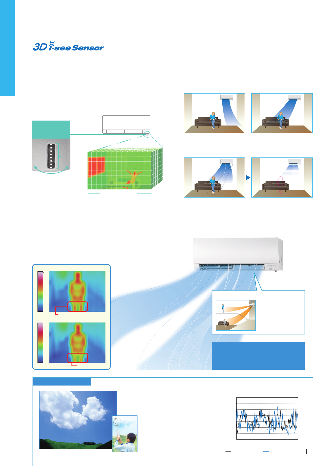
Base data for Natural Flow
Natural Flow
To create “healthy” airow, the most important aspect is that the ow of air
feels natural. Mitsubishi Electric’ s solution to this is Natural Flow, only
possible thanks to our technology that freely and exibly controls airow.
Kirigamine Highland is one of the most
famous sightseeing spots in Japan, and is
visited by a large number of people for its
pleasant and comfortable environment. At
Mitsubishi Electric, we have attempted to
recreate this Kirigamine Highland comfort.
As part of development, seeking to create a
natural airow, we measured actual data
on the refreshing breezes of Kirigamine
Highland. Through imitating the natural
waveforms of this data, we have been able to
recreate almost-imperceptible currents of
gently comforting airow.
Analysis of natural wind
Wind of Kirigamine
Through realizing airflow that imitates a
natural breeze, we have avoided the
unpleasant feeling of being hit directly by
constant, unnatural airflow.
Direct airflow
(in Cooling)
Legs become too cold
Natural Flow (in Cooling)
Kirigamine Highland
Gentle airflow that avoids overcooling
Mitsubishi Electric’ s double
vane separates the airow in
the left and right directions to
deliver airow not only across
a wide area of the room, but
also simultaneously to two
people in dierent locations.
Double Vane
Natural Flow(FH SERIES)
Wind speed [cm/s]
Time [s]
0
0
20
40
60
80
100
120
140
20 40 60 80 100120
measuring actual data
of natural wind
The FH Series is equipped with 3D i-see Sensor, an infrared-ray sensor that
measures the temperature at distant positions. While moving to the left
and right, eight vertically arranged sensor elements analyze the room
temperature in three dimensions. This detailed analysis makes it possible
to judge where people are in the room, thus allowing creation of
features such as “Indirect airow,” to avoid airow hitting people directly,
and “direct airow” to deliver airow to where people are.
8 × 94 areas
(Image)
Divided into 94
Sensor with
eight elements
Sensor measures while
moving to the left to right
The indirect airow setting can be used when
the ow of air feels too strong or direct. For
example, it can be used during cooling to avert
airow and prevent body temperature from
becoming excessively cooled.
Indirect Airflow
The sensors detect whether there are people in the room. When no-one is in the room, the
unit automatically switches to energy-saving mode.
The “3D i-see Sensor” detects people’s absence and the power consumption is automatically reduced approxi-
mately 10% after 10 minutes and 20% after 60 minutes.
Absence Detection
This setting can be used to directly target
airow at people such as for immediate
comfort when coming indoors on a hot
(cold) day.
Direct Airflow
40.0
23.0
40.0
23.0
MUZ-FH25/35VE
MUZ-FH50VE
SEER
A
+++
SCOP
A
+++
VERTICALHORIZONTAL
OptionalOptional
Optional Optional
Indoor Unit Outdoor Unit
MSZ-F SERIES
Remote Controller
Please fill out the requested information
Please fill out the requested information
HUMAN
Natural Flow
25 / 35 25 / 35
Wi-Fi
Interface
Electrostatic
Anti-allergy
MSZ-FH25/35/50VE2
24-hour Timer
35
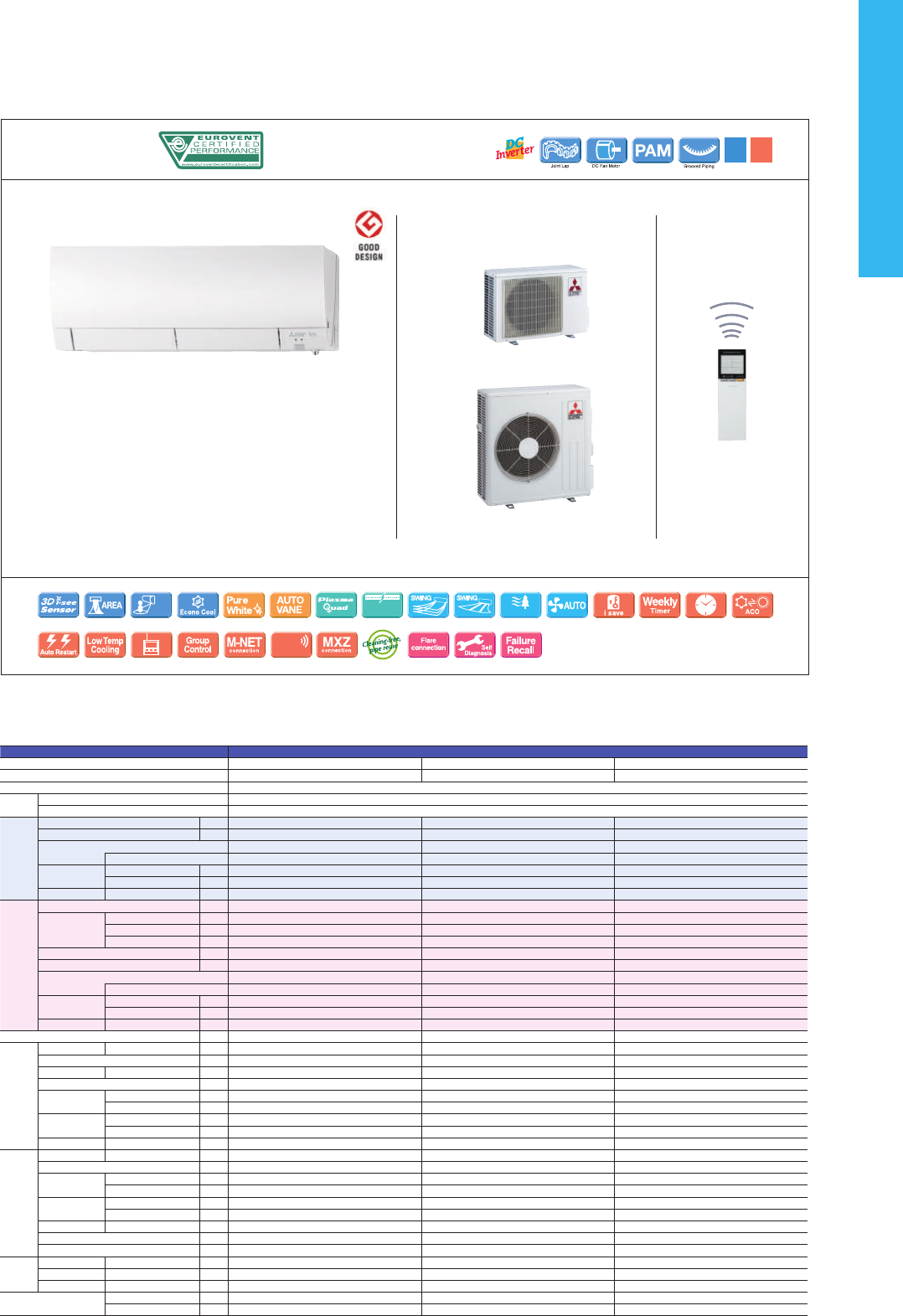
Base data for Natural Flow
Natural Flow
To create “healthy” airow, the most important aspect is that the ow of air
feels natural. Mitsubishi Electric’ s solution to this is Natural Flow, only
possible thanks to our technology that freely and exibly controls airow.
Kirigamine Highland is one of the most
famous sightseeing spots in Japan, and is
visited by a large number of people for its
pleasant and comfortable environment. At
Mitsubishi Electric, we have attempted to
recreate this Kirigamine Highland comfort.
As part of development, seeking to create a
natural airow, we measured actual data
on the refreshing breezes of Kirigamine
Highland. Through imitating the natural
waveforms of this data, we have been able to
recreate almost-imperceptible currents of
gently comforting airow.
Analysis of natural wind
Wind of Kirigamine
Through realizing airflow that imitates a
natural breeze, we have avoided the
unpleasant feeling of being hit directly by
constant, unnatural airflow.
Direct airflow
(in Cooling)
Legs become too cold
Natural Flow (in Cooling)
Kirigamine Highland
Gentle airflow that avoids overcooling
Mitsubishi Electric’ s double
vane separates the airow in
the left and right directions to
deliver airow not only across
a wide area of the room, but
also simultaneously to two
people in dierent locations.
Double Vane
Natural Flow(FH SERIES)
Wind speed [cm/s]
Time [s]
0
0
20
40
60
80
100
120
140
20 40 60 80 100120
measuring actual data
of natural wind
The FH Series is equipped with 3D i-see Sensor, an infrared-ray sensor that
measures the temperature at distant positions. While moving to the left
and right, eight vertically arranged sensor elements analyze the room
temperature in three dimensions. This detailed analysis makes it possible
to judge where people are in the room, thus allowing creation of
features such as “Indirect airow,” to avoid airow hitting people directly,
and “direct airow” to deliver airow to where people are.
8 × 94 areas
(Image)
Divided into 94
Sensor with
eight elements
Sensor measures while
moving to the left to right
The indirect airow setting can be used when
the ow of air feels too strong or direct. For
example, it can be used during cooling to avert
airow and prevent body temperature from
becoming excessively cooled.
Indirect Airflow
The sensors detect whether there are people in the room. When no-one is in the room, the
unit automatically switches to energy-saving mode.
The “3D i-see Sensor” detects people’s absence and the power consumption is automatically reduced approxi-
mately 10% after 10 minutes and 20% after 60 minutes.
Absence Detection
This setting can be used to directly target
airow at people such as for immediate
comfort when coming indoors on a hot
(cold) day.
Direct Airflow
40.0
23.0
40.0
23.0
MUZ-FH25/35VE
MUZ-FH50VE
SEER
A
+++
SCOP
A
+++
VERTICALHORIZONTAL
OptionalOptional
Optional Optional
Indoor Unit Outdoor Unit
MSZ-F SERIES
Remote Controller
Please fill out the requested information
Please fill out the requested information
HUMAN
Natural Flow
25 / 35 25 / 35
Wi-Fi
Interface
Electrostatic
Anti-allergy
MSZ-FH25/35/50VE2
24-hour Timer
36
Type Inverter Heat Pump
Indoor Unit MSZ-FH25VE(2) MSZ-FH35VE(2) MSZ-FH50VE(2)
Outdoor Unit MUZ-FH25VE MUZ-FH35VE MUZ-FH50VE
Refrigerant R410A
(*1)
Power
Supply
Source
Outdoor Power supply
Outdoor ( V / Phase / Hz )
230/Single/50
Cooling
Design load
kW
2.5 3.5 5.0
Annual electricity consumption
(*2)
kWh/a
96 138 244
SEER
(*4)
9.1 8.9 7.2
Energy efficiency class
A
+++
A
+++
A
++
Capacity
Rated
kW
2.5 3.5 5.0
Min-Max
kW
1.4-3.5 0.8-4.0 1.9-6.0
Total Input
Rated
kW
0.485 0.820 1.380
Heating
(Average
Season)
(*5)
Design load
kW
3.0(-10°C) 3.6(-10°C) 4.5(-10°C)
Declared
Capacity
at reference design temperature
kW
3.0(-10°C) 3.6(-10°C) 4.5(-10°C)
at bivalent temperature
kW
3.0(-10°C) 3.6(-10°C) 4.5(-10°C)
at operation limit temperature
kW
2.5(-15°C) 3.2(-15°C) 5.2(-15°C)
Back up heating capacity
kW
0.0(-10°C) 0.0(-10°C) 0.0(-10°C)
Annual electricity consumption
(*2)
kWh/a
819 986 1372
SCOP
(*4)
5.1 5.1 4.6
Energy efficiency class
A
+++
A
+++
A
++
Capacity
Rated
kW
3.2 4.0 6.0
Min-Max
kW
1.8-5.5 1.0-6.3 1.7-8.7
Total Input
Rated
kW
0.580 0.800 1.480
Operating Current (Max)
A
9.6 10.0 14.0
Indoor
Unit
Input
Rated
kW
0.029 0.029 0.031
Operating Current(Max)
A
0.4 0.4 0.4
Dimensions
H*W*D
mm
305(+17)-925-234 305(+17)-925-234 305(+17)-925-234
Weight
kg
13.5 13.5 13.5
Air Volume (SLo-Lo-
Mid-Hi-SHi
(*3)
(Dry/Wet))
Cooling
m
3
/min
3.9-4.7-6.3-8.6-11.6 3.9-4.7-6.3-8.6-11.6 6.4-7.4-8.6-10.1-12.4
Heating
m
3
/min
4.0-4.7-6.4-9.2-13.2 4.0-4.7-6.4-9.2-13.2 5.7-7.2-9.0-11.2-14.6
Sound Level (SPL)
(SLo-Lo-Mid-Hi-SHi
(*3)
)
Cooling
dB(A)
20-23-29-36-42 21-24-29-36-42 27-31-35-39-44
Heating
dB(A)
20-24-29-36-44 21-24-29-36-44 25-29-34-39-46
Sound Level (PWL)
Cooling
dB(A)
58 58 60
Outdoor
Unit
Dimensions
H*W*D
mm
550-800-285 550-800-285 880-840-330
Weight
kg
37 37 55
Air Volume
Cooling
m
3
/min
31.3 33.6 48.8
Heating
m
3
/min
31.3 33.6 51.3
Sound Level (SPL)
Cooling
dB(A)
46 49 51
Heating
dB(A)
49 50 54
Sound Level (PWL)
Cooling
dB(A)
60 61 64
Operating Current (Max)
A
9.6 9.6 13.6
Breaker Size
A
9.2 10 16
Ext.
Piping
Diameter
Liquid/Gas
mm
6.35/9.52 6.35/9.52 6.35 / 12.7
Max.Length
Out-In
m
20 20 30
Max.Height
Out-In
m
12 12 15
Guaranteed Operating
Range (Outdoor)
Cooling
˚C
-10 ~ +46 -10 ~ +46 -10 ~ +46
Heating
˚C
-15 ~ +24 -15 ~ +24 -15 ~ +24
(*1) Refrigerant leakage contributes to climate change. Refrigerant with lower global warming potential (GWP) would contribute less to global warming than a refrigerant with higher GWP, if leaked to the atmosphere. This appliance contains a refrigerant fluid with
a GWP equal to 1975. This means that if 1 kg of this refrigerant fluid would be leaked to the atmosphere, the impact on global warming would be 1975 times higher than 1 kg of CO
2, over a period of 100 years. Never try to interfere with the refrigerant circuit
yourself or disassemble the product yourself and always ask a professional.
(*2) Energy consumption based on standard test results.Actual energy consumption will depend on how the appliance is used and where it is located.
(*3) SHi: Super High
(*4) SEER, SCOP and other related description are based on COMMISSION DELEGATED REGULATION (EU) No.626/2011. The temperature conditions for calculating SCOP are based on “Average Season”.
(*5) Please see page 47 for heating (warmer season) specifications.
MSZ-E
SERIES
Developed to complement modern interior room décor, Kirigamine ZEN air
conditioners are available in three colours specially chosen to blend in
naturally wherever installed.
Stylish Line-up Matches
Any Room Décor
The streamlined wall-mounted indoor units have eloquent sil-
ver-bevelled edges, expressing sophistication and quality. Com-
bining impressively low power consumption and quiet yet pow-
erful performance, these units provide a best-match scenario
for diverse interior designs while simultaneously ensuring maxi-
mum room and energy savings.
Energy-ecient Operation
All models in the series have achieved high energy-savings rating, and are contributing to reduced energy consumption in homes, oces and a range of other set-
tings. Oered in a variety of output capacities and installation patterns, the vast applicability promises an ideal match for any user.
Quiet Comfort All Day Long
Mitsubishi Electric’s advanced “Silent Mode” fan speed setting provides su-
per-quiet operation as low as 21dB for EF18/22/25/35 models. This unique
feature makes the Kirigamine ZEN series ideal for use in any situation.
Superior Exterior
and Operating Design Concept
The indoor unit of the Kirigamine ZEN keeps its amazingly thin form even
during operation. The only physical change notable is the movement of
the variable vent. As a result, a slim attractive look is maintained.
Closed Open
Low Standby Power
Electrical devices consume standby power even when they are not in
actual use. While we obviously strive to reduce power consumption
during actual use, reducing this wasted power that cannot be seen is also
very important.
Outdoor Units for Cold Region
Single split-type outdoor units are available in both standard and heater-
equipped units. An electric heater is installed in each unit to prevent
freezing in cold outdoor environments
MUZ-EF25/35VE
MUZ-EF25/35VEH
Standard Units
Heater Installed
(25/35)
SEER
A
+++
SCOP
A
++
● Noise Level
10dB40dB60dB80dB
Subway car
interior
Quiet passenger
car interior
(40km/h)
Library interior
An in-company
investigation
Human
hearing limits
(Extremely quiet)
Sound of
rustling leaves
–
–
A
+++
/A
++
(A
++
*)
A
+++
/A
++
(A
+
*)
A
++
/A
++
A
++
/A
+
2D33VA
MUZ-EF25/35VE(H)
MUZ-EF42/50VE
2D40VA 2D53VA 3D54VA 3D68VA 4D72VA 4D83VA 5D102VA6C122VA
*VEH
MSZ-EF18VE2
MSZ-EF22VE2
MSZ-EF25VE2
MSZ-EF35VE2
MSZ-EF42VE2
MSZ-EF50VE2
Outdoor
Indoor
CompatibilityRank A for single connection
MXZ
Only
21dB
(for EF18/22/25/35 models)
25-35 25-42*
*Soft-dry Cloth is enclosed with Black models.
Indoor Unit
MUZ-EF25/35VE
(
H
)
,42VE
MUZ-EF50VE
MSZ-EF18/22/25/35/42/50VE3W
MSZ-EF18/22/25/35/42/50VE3S
MSZ-EF18/22/25/35/42/50VE3B*
White
Silver
Black
Outdoor Unit
MSZ-E SERIES
Remote Controller
SEER
A
+++
SCOP
A
++
Optional Optional
Optional
25 - 35 25 - 42*
*except for VEH
Electrostatic
Anti-allergy
Please fill out the requested information
Please fill out the requested information
*except for VEH
without
“Low standby power”
with
“Low standby power”
around
10W
below
1W
around
90%
reduction
around
90%
reduction
Nano
Platinum
MSZ-EF18-50VE3B
Optional
Wi-Fi
Interface
37
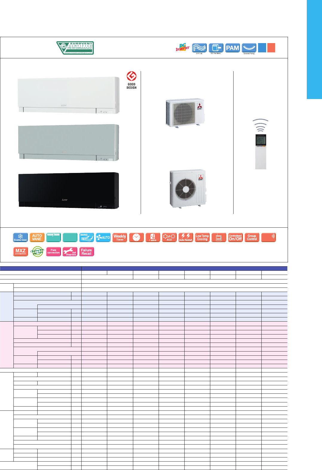
MSZ-E
SERIES
Developed to complement modern interior room décor, Kirigamine ZEN air
conditioners are available in three colours specially chosen to blend in
naturally wherever installed.
Stylish Line-up Matches
Any Room Décor
The streamlined wall-mounted indoor units have eloquent sil-
ver-bevelled edges, expressing sophistication and quality. Com-
bining impressively low power consumption and quiet yet pow-
erful performance, these units provide a best-match scenario
for diverse interior designs while simultaneously ensuring maxi-
mum room and energy savings.
Energy-ecient Operation
All models in the series have achieved high energy-savings rating, and are contributing to reduced energy consumption in homes, oces and a range of other set-
tings. Oered in a variety of output capacities and installation patterns, the vast applicability promises an ideal match for any user.
Quiet Comfort All Day Long
Mitsubishi Electric’s advanced “Silent Mode” fan speed setting provides su-
per-quiet operation as low as 21dB for EF18/22/25/35 models. This unique
feature makes the Kirigamine ZEN series ideal for use in any situation.
Superior Exterior
and Operating Design Concept
The indoor unit of the Kirigamine ZEN keeps its amazingly thin form even
during operation. The only physical change notable is the movement of
the variable vent. As a result, a slim attractive look is maintained.
Closed Open
Low Standby Power
Electrical devices consume standby power even when they are not in
actual use. While we obviously strive to reduce power consumption
during actual use, reducing this wasted power that cannot be seen is also
very important.
Outdoor Units for Cold Region
Single split-type outdoor units are available in both standard and heater-
equipped units. An electric heater is installed in each unit to prevent
freezing in cold outdoor environments
MUZ-EF25/35VE
MUZ-EF25/35VEH
Standard Units
Heater Installed
(25/35)
SEER
A
+++
SCOP
A
++
● Noise Level
10dB40dB60dB80dB
Subway car
interior
Quiet passenger
car interior
(40km/h)
Library interior
An in-company
investigation
Human
hearing limits
(Extremely quiet)
Sound of
rustling leaves
–
–
A
+++
/A
++
(A
++
*)
A
+++
/A
++
(A
+
*)
A
++
/A
++
A
++
/A
+
2D33VA
MUZ-EF25/35VE(H)
MUZ-EF42/50VE
2D40VA 2D53VA 3D54VA 3D68VA 4D72VA 4D83VA 5D102VA6C122VA
*VEH
MSZ-EF18VE2
MSZ-EF22VE2
MSZ-EF25VE2
MSZ-EF35VE2
MSZ-EF42VE2
MSZ-EF50VE2
Outdoor
Indoor
CompatibilityRank A for single connection
MXZ
Only
21dB
(for EF18/22/25/35 models)
25-35 25-42*
*Soft-dry Cloth is enclosed with Black models.
Indoor Unit
MUZ-EF25/35VE
(
H
)
,42VE
MUZ-EF50VE
MSZ-EF18/22/25/35/42/50VE3W
MSZ-EF18/22/25/35/42/50VE3S
MSZ-EF18/22/25/35/42/50VE3B*
White
Silver
Black
Outdoor Unit
MSZ-E SERIES
Remote Controller
SEER
A
+++
SCOP
A
++
Optional Optional
Optional
25 - 35 25 - 42*
*except for VEH
Electrostatic
Anti-allergy
Please fill out the requested information
Please fill out the requested information
*except for VEH
without
“Low standby power”
with
“Low standby power”
around
10W
below
1W
around
90%
reduction
around
90%
reduction
Nano
Platinum
MSZ-EF18-50VE3B
Optional
Wi-Fi
Interface
38
Type Inverter Heat Pump
Indoor Unit MSZ-EF18VE2(3) MSZ-EF22VE2(3) MSZ-EF25VE2(3) MSZ-EF25VE2(3) MSZ-EF35VE2(3) MSZ-EF35VE2(3) MSZ-EF42VE2(3) MSZ-EF50VE2(3)
Outdoor Unit for MXZ connection MUZ-EF25VE MUZ-EF25VEH MUZ-EF35VE MUZ-EF35VEH MUZ-EF42VE MUZ-EF50VE
Refrigerant R410A
(*1)
Power
Supply
Source
Outdoor Power supply
Outdoor ( V / Phase / Hz )
230/Single/50
Cooling
Design load
kW
- - 2.5 2.5 3.5 3.5 4.2 5.0
Annual electricity consumption
(*2)
kWh/a
- - 103 103 144 144 192 244
SEER
(*4)
- - 8.5 8.5 8.5 8.5 7.7 7.2
Energy efficiency class
- - A
+++
A
+++
A
+++
A
+++
A
++
A
++
Capacity
Rated
kW
- - 2.5 2.5 3.5 3.5 4.2 5.0
Min-Max
kW
- - 1.2-3.4 1.2-3.4 1.4-4.0 1.4-4.0 0.9-4.6 1.4-5.4
Total Input
Rated
kW
- - 0.545 0.545 0.910 0.910 1.280 1.560
Heating
(Average
Season)
(*5)
Design load
kW
- - 2.4(-10ºC) 2.4(-10ºC) 2.9(-10ºC) 2.9(-10ºC) 3.8(-10ºC) 4.2(-10ºC)
Declared
Capacity
at reference design temperature
kW
- - 2.4(-10ºC) 2.4(-10ºC) 2.9(-10ºC) 2.9(-10ºC) 3.8(-10ºC) 4.2(-10ºC)
at bivalent temperature
kW
- - 2.4(-10ºC) 2.4(-10ºC) 2.9(-10ºC) 2.9(-10ºC) 3.8(-10ºC) 4.2(-10ºC)
at operation limit temperature
kW
- - 2.0(-15ºC) 1.6(-20ºC) 2.4(-15ºC) 1.7(-20ºC) 3.4(-15ºC) 3.5(-15ºC)
Back up heating capacity
kW
- - 0.0(-10ºC) 0.0(-10ºC) 0.0(-10ºC) 0.0(-10ºC) 0.0(-10ºC) 0.0(-10ºC)
Annual electricity consumption
(*2)
kWh/a
- - 716 730 882 910 1155 1309
SCOP
(*4)
- - 4.7 4.6 4.6 4.5 4.6 4.5
Energy efficiency class
- - A
++
A
++
A
++
A
+
A
++
A
+
Capacity
Rated
kW
- - 3.2 3.2 4.0 4.0 5.4 5.8
Min-Max
kW
- - 1.1-4.2 1.1-4.2 1.8-5.5 1.8-5.5 1.4-6.3 1.6-7.5
Total Input
Rated
kW
- - 0.700 0.700 0.955 0.955 1.460 1.565
Operating Current (Max)
A
- - 7.3 7.3 8.5 8.5 9.5 12.4
Indoor
Unit
Input
Rated
kW
0.027 0.027 0.027 0.027 0.031 0.031 0.031 0.034
Operating Current(Max)
A
0.3 0.3 0.3 0.3 0.3 0.3 0.3 0.4
Dimensions
H*W*D
mm
299-885-195 299-885-195 299-885-195 299-885-195 299-885-195 299-885-195 299-885-195 299-885-195
Weight
kg
11.5 11.5 11.5 11.5 11.5 11.5 11.5 11.5
Air Volume (SLo-Lo-
Mid-Hi-SHi
(*3)
(Dry/Wet))
Cooling
m
3
/min
4.0 - 4.6 - 6.3 - 8.3 - 10.5 4.0 - 4.6 - 6.3 - 8.3 - 10.5 4.0 - 4.6 - 6.3 - 8.3 - 10.5 4.0 - 4.6 - 6.3 - 8.3 - 10.5 4.0 - 4.6 - 6.3 - 8.3 - 10.5 4.0 - 4.6 - 6.3 - 8.3 - 10.5 5.8 - 6.6 - 7.7 - 8.9 - 10.3 5.8 - 6.8 - 7.9 - 9.3 - 11.0
Heating
m
3
/min
4.0 - 4.6 - 6.2 - 8.9 - 11.9 4.0 - 4.6 - 6.2 - 8.9 - 11.9 4.0 - 4.6 - 6.2 - 8.9 - 11.9 4.0 - 4.6 - 6.2 - 8.9 - 11.9 4.0 - 4.6 - 6.2 - 8.9 - 12.7 4.0 - 4.6 - 6.2 - 8.9 - 12.7 5.5 - 6.3 - 7.8 - 9.9 - 12.7 6.4 - 7.3 - 9.0 - 11.1 - 13.2
Sound Level (SPL)
(SLo-Lo-Mid-Hi-SHi
(*3)
)
Cooling
dB(A)
21 - 23 - 29 - 36 - 42 21 - 23 - 29 - 36 - 42 21 - 23 - 29 - 36 - 42 21 - 23 - 29 - 36 - 42 21 - 24 - 29 - 36 - 42 21 - 24 - 29 - 36 - 42 28 - 31 - 35 - 39 - 42 30 - 33 - 36 - 40 - 43
Heating
dB(A)
21 - 24 - 29 - 37 - 45 21 - 24 - 29 - 37 - 45 21 - 24 - 29 - 37 - 45 21 - 24 - 29 - 37 - 45 21 - 24 - 30 - 38 - 46 21 - 24 - 30 - 38 - 46 28 - 30 - 35 - 41 - 48 30 - 33 - 37 - 43 - 49
Sound Level (PWL)
Cooling
dB(A)
- - 60 60 60 60 60 60
Outdoor
Unit
Dimensions
H*W*D
mm
- - 550-800-285 550-800-285 550-800-285 550-800-285 550-800-285 880-840-330
Weight
kg
- - 30 30 35 35 35 54
Air Volume
Cooling
m
3
/min
- - 32.6 32.6 33.6 33.6 35.2 44.6
Heating
m
3
/min
- - 32.2 32.2 33.6 33.6 33.6 44.6
Sound Level (SPL)
Cooling
dB(A)
- - 47 47 49 49 50 52
Heating
dB(A)
- - 48 48 50 50 51 52
Sound Level (PWL)
Cooling
dB(A)
- - 58 58 61 61 62 65
Operating Current (Max)
A
- - 7.0 7.0 8.2 8.2 9.2 12.0
Breaker Size
A
- - 10 10 10 10 10 16
Ext.
Piping
Diameter
Liquid/Gas
mm
- - 6.35 / 9.52 6.35 / 9.52 6.35 / 9.52 6.35 / 9.52 6.35 / 9.52 6.35 / 12.7
Max.Length
Out-In
m
- - 20 20 20 20 20 30
Max.Height
Out-In
m
- - 12 12 12 12 12 15
Guaranteed Operating
Range (Outdoor)
Cooling
˚C
- - -10 ~ +46 -10 ~ +46 -10 ~ +46 -10 ~ +46 -10 ~ +46 -10 ~ +46
Heating
˚C
- - -15 ~ +24 -20 ~ +24 -15 ~ +24 -20 ~ +24 -15 ~ +24 -15 ~ +24
(*1) Refrigerant leakage contributes to climate change. Refrigerant with lower global warming potential (GWP) would contribute less to global warming than a refrigerant with higher GWP, if leaked to the atmosphere. This appliance contains a refrigerant fluid with
a GWP equal to 1975. This means that if 1 kg of this refrigerant fluid would be leaked to the atmosphere, the impact on global warming would be 1975 times higher than 1 kg of CO
2, over a period of 100 years. Never try to interfere with the refrigerant circuit
yourself or disassemble the product yourself and always ask a professional.
(*2) Energy consumption based on standard test results.Actual energy consumption will depend on how the appliance is used and where it is located.
(*3) SHi: Super High
(*4) SEER, SCOP and other related description are based on COMMISSION DELEGATED REGULATION (EU) No.626/2011. The temperature conditions for calculating SCOP are based on “Average Season”.
(*5) Please see page 47 for heating (warmer season) specifications.
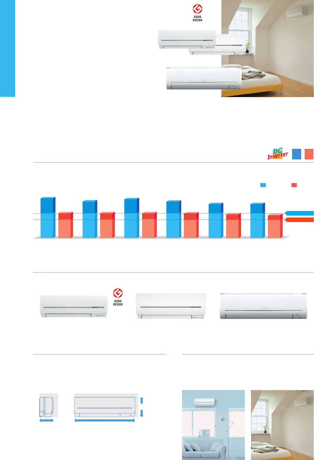
MSZ-G
SERIES
MSZ-S
SERIES
Introducing a compact and stylish indoor unit with
amazingly quiet performance.
Not only are neat
installations in small bedrooms possible, increase
energy-savings by selecting the optimal capacity required
for each room.
MSZ-GF60/71VE2
MSZ-SF15/20VA
MSZ-SF25/35/42/50VE3
•
Start by pushing the “SET” button and follow the instructions to set the desired patterns. Once all of
the desired patterns are input, point the top end of the remote controller at the indoor unit and
push the “SET” button one more time. (Push the “SET” button only after inputting all of the desired
patterns into the remote controller memory. Pushing the “CANCEL” button will end the set-up pro-
cess without sending the operation patterns to the indoor unit).
•
It takes a few seconds to transmit the Weekly Timer operation patterns to the indoor unit. Please
continue to point the remote controller at the indoor unit until all data has been sent.
•
When “Weekly Timer” is set, temperature can not be set 10°C.
■
Easy set-up using dedicated buttons
Ready to set
Complete
Select ON/OFF Select the time
Set the temperature
Select the daySelect the period
How to set
the Weekly
Timer
PUSH PUSH
PUSHPUSHPUSH
PUSH
PUSH
Pattern Settings: Input up to four settings for each day
Settings:
•
Start/Stop operation
•
Temperature setting
✽
The operation mode cannot be set.
■ Example Operation Pattern (Winter/Heating mode)
Mon. Tues.Wed.Thurs.Fri.Sat. Sun.
ON 20°CON 20°C ON 20°C ON 20°CON 20°C ON 20°C ON 20°C
Automatically changes to high-power operation at wake-up time
Automatically lowers temperature at bedtime for energy-saving operation at night
ON 18°CON 18°C ON 18°C ON 18°CON 18°C ON 18°C ON 18°C
Settings
(during sleeping hours)
The remote controller is
equipped with buttons that
are used exclusively for set-
ting the Weekly Timer. Set-
ting operation patterns is
easy and quick.
Automatically turned o during work hours
Midday is warmer,
so the temperature is set lower
OFFOFFOFF OFFOFF ON 18°C ON 18°C
Automatically turns on, synchronized with arrival at home
Automatically raises temperature setting to
match time when outside-air temperature is low
ON 20°CON 20°C ON 20°C ON 20°CON 20°C ON 20°C ON 20°C
MSZ-SF15 / 20VA*
(MSZ-SF15/20VA)
*for MXZ connection
MSZ-SF25 / 35 / 42 / 50VE3 MSZ-GF60 / 71VE2
Wide Line-up
Eight dierent indoor units (Model 15-71) are available to meet your diversied air conditioning needs.
“Weekly Timer”
Easily set desired temperatures and operation start/stop times to match lifestyle patterns. Reduce wasted energy consumption by using the timer to prevent
forgetting to turn o the unit and eliminate temperature setting adjustments.
Low Standby Power
Electrical devices consume standby power even when they are not in actual use. While
we obviously strive to reduce power consumption during actual use, reducing this
wasted power that cannot be seen is also very important.
“Rank A
++
/A
+
” Energy Savings Achieved for Entire Range of Series
All models in the series, from the low-capacity 25 to the high-capacity 71, have achieved the “Rank A
++
” for SEER and “Rank A
+
” for SCOP as energy-savings
rating. For home use, such as in bedrooms and living rooms, to light commercial use, such as in oces, our air conditioners are contributing to reduced
energy consumption in a wide range.
SEER
A
++
SCOP
A
+
“i save” is a simplied setting function that recalls the preferred (preset)
temperature by pressing a single button on the remote controller. Press
the same button twice in repetition to immediately return to the previous
temperature setting. Using this function contributes to comfortable,
waste-free operation, realising the most suitable air conditioning settings
and saving on power consumption when, for example, leaving the room
or going to bed.
“i save” Mode
✽ Temperature can be preset to 10°C when heating in the “i-save” mode.
22°C
18°C
Heating Heating
25-71 25-71
Compact and Stylish
The stylish, square indoor unit adds a touch of class to any room interior.
The compact design is 64mm thinner than our previous indoor unit with
the lowest output capacity (MSZ-GE22VA).
Family Design
(MSZ-SF15/20/25/35/42/50)
Models in the 25-50 class are introduced as single-split units while
retaining the popular design of the SF15/20VA* as indoor units
exclusively for multi-systems. From small rooms to living rooms, it is
possible to coordinate residences with a unied design.
*Size may vary.
64mm less
38mm less
Comparison with our previous model GE
45mm less
Air Purifying Filter
This lter incorporates Silver-ionized agents that generate stable antibac-
terial and deodourising eects. The size of the three-dimensional surface
has been increased as well, enlarging the lter capture area. These fea-
tures give the Purifying Filter better dust collection performance than
conventional lters. The superior air-cleaning eectiveness raises room
comfort yet an-other level.
✽ It is okay to wash the lter with water
(air-cleaning eect is maintained)
3D surface (Waved surface)
Outdoor Units for Cold Region
Single split-type outdoor units are available in both standard and
heater-equipped units. An electric heater is installed in each unit to pre-
vent freezing in cold outdoor environments.
MUZ-SF25/35/42VE MUZ-SF50VE
MUZ-SF25/35/42VEH MUZ-SF50VEH
Standard Units
Heater Installed
(25/35/42/50)
without
“Low standby power”
with
“Low standby power”
around
10W
below
1W
around
90%
reduction
around
90%
reduction
Cooling Heating
SCOP
4.4
SEER
7.2
SCOP
4.4
SEER
7.5
SCOP
4.4
SEER
7.2
SCOP
4.4
SCOP
4.3
SEER
6.8
SCOP
4.2
MSZ-SF25VE MSZ-SF35VE MSZ-SF42VE MSZ-SF50VE MSZ-GF60VE MSZ-GF71VE
SEER
6.8
SEER
7.6
SEER Rank A(5.1)
SCOP Rank A(3.8)
39
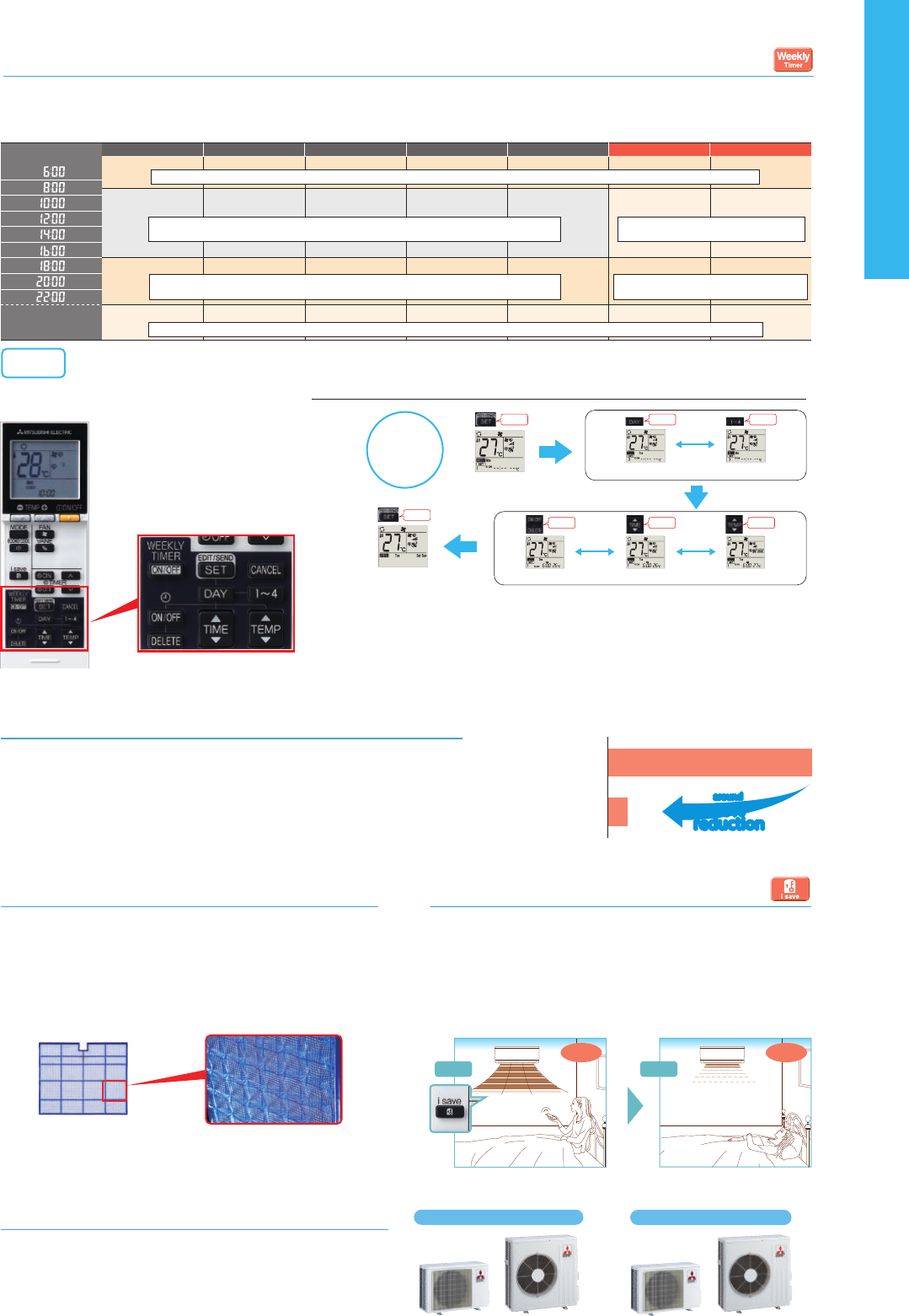
MSZ-G
SERIES
MSZ-S
SERIES
Introducing a compact and stylish indoor unit with
amazingly quiet performance.
Not only are neat
installations in small bedrooms possible, increase
energy-savings by selecting the optimal capacity required
for each room.
MSZ-GF60/71VE2
MSZ-SF15/20VA
MSZ-SF25/35/42/50VE3
•
Start by pushing the “SET” button and follow the instructions to set the desired patterns. Once all of
the desired patterns are input, point the top end of the remote controller at the indoor unit and
push the “SET” button one more time. (Push the “SET” button only after inputting all of the desired
patterns into the remote controller memory. Pushing the “CANCEL” button will end the set-up pro-
cess without sending the operation patterns to the indoor unit).
•
It takes a few seconds to transmit the Weekly Timer operation patterns to the indoor unit. Please
continue to point the remote controller at the indoor unit until all data has been sent.
•
When “Weekly Timer” is set, temperature can not be set 10°C.
■
Easy set-up using dedicated buttons
Ready to set
Complete
Select ON/OFF Select the time
Set the temperature
Select the daySelect the period
How to set
the Weekly
Timer
PUSH PUSH
PUSHPUSHPUSH
PUSH
PUSH
Pattern Settings: Input up to four settings for each day
Settings:
•
Start/Stop operation
•
Temperature setting
✽
The operation mode cannot be set.
■ Example Operation Pattern (Winter/Heating mode)
Mon. Tues.Wed.Thurs.Fri.Sat. Sun.
ON 20°CON 20°C ON 20°C ON 20°CON 20°C ON 20°C ON 20°C
Automatically changes to high-power operation at wake-up time
Automatically lowers temperature at bedtime for energy-saving operation at night
ON 18°CON 18°C ON 18°C ON 18°CON 18°C ON 18°C ON 18°C
Settings
(during sleeping hours)
The remote controller is
equipped with buttons that
are used exclusively for set-
ting the Weekly Timer. Set-
ting operation patterns is
easy and quick.
Automatically turned o during work hours
Midday is warmer,
so the temperature is set lower
OFFOFFOFF OFFOFF ON 18°C ON 18°C
Automatically turns on, synchronized with arrival at home
Automatically raises temperature setting to
match time when outside-air temperature is low
ON 20°CON 20°C ON 20°C ON 20°CON 20°C ON 20°C ON 20°C
MSZ-SF15 / 20VA*
(MSZ-SF15/20VA)
*for MXZ connection
MSZ-SF25 / 35 / 42 / 50VE3 MSZ-GF60 / 71VE2
Wide Line-up
Eight dierent indoor units (Model 15-71) are available to meet your diversied air conditioning needs.
“Weekly Timer”
Easily set desired temperatures and operation start/stop times to match lifestyle patterns. Reduce wasted energy consumption by using the timer to prevent
forgetting to turn o the unit and eliminate temperature setting adjustments.
Low Standby Power
Electrical devices consume standby power even when they are not in actual use. While
we obviously strive to reduce power consumption during actual use, reducing this
wasted power that cannot be seen is also very important.
“Rank A
++
/A
+
” Energy Savings Achieved for Entire Range of Series
All models in the series, from the low-capacity 25 to the high-capacity 71, have achieved the “Rank A
++
” for SEER and “Rank A
+
” for SCOP as energy-savings
rating. For home use, such as in bedrooms and living rooms, to light commercial use, such as in oces, our air conditioners are contributing to reduced
energy consumption in a wide range.
SEER
A
++
SCOP
A
+
“i save” is a simplied setting function that recalls the preferred (preset)
temperature by pressing a single button on the remote controller. Press
the same button twice in repetition to immediately return to the previous
temperature setting. Using this function contributes to comfortable,
waste-free operation, realising the most suitable air conditioning settings
and saving on power consumption when, for example, leaving the room
or going to bed.
“i save” Mode
✽ Temperature can be preset to 10°C when heating in the “i-save” mode.
22°C
18°C
Heating Heating
25-71 25-71
Compact and Stylish
The stylish, square indoor unit adds a touch of class to any room interior.
The compact design is 64mm thinner than our previous indoor unit with
the lowest output capacity (MSZ-GE22VA).
Family Design
(MSZ-SF15/20/25/35/42/50)
Models in the 25-50 class are introduced as single-split units while
retaining the popular design of the SF15/20VA* as indoor units
exclusively for multi-systems. From small rooms to living rooms, it is
possible to coordinate residences with a unied design.
*Size may vary.
64mm less
38mm less
Comparison with our previous model GE
45mm less
Air Purifying Filter
This lter incorporates Silver-ionized agents that generate stable antibac-
terial and deodourising eects. The size of the three-dimensional surface
has been increased as well, enlarging the lter capture area. These fea-
tures give the Purifying Filter better dust collection performance than
conventional lters. The superior air-cleaning eectiveness raises room
comfort yet an-other level.
✽ It is okay to wash the lter with water
(air-cleaning eect is maintained)
3D surface (Waved surface)
Outdoor Units for Cold Region
Single split-type outdoor units are available in both standard and
heater-equipped units. An electric heater is installed in each unit to pre-
vent freezing in cold outdoor environments.
MUZ-SF25/35/42VE MUZ-SF50VE
MUZ-SF25/35/42VEH MUZ-SF50VEH
Standard Units
Heater Installed
(25/35/42/50)
without
“Low standby power”
with
“Low standby power”
around
10W
below
1W
around
90%
reduction
around
90%
reduction
Cooling Heating
SCOP
4.4
SEER
7.2
SCOP
4.4
SEER
7.5
SCOP
4.4
SEER
7.2
SCOP
4.4
SCOP
4.3
SEER
6.8
SCOP
4.2
MSZ-SF25VE MSZ-SF35VE MSZ-SF42VE MSZ-SF50VE MSZ-GF60VE MSZ-GF71VE
SEER
6.8
SEER
7.6
SEER Rank A(5.1)
SCOP Rank A(3.8)
40
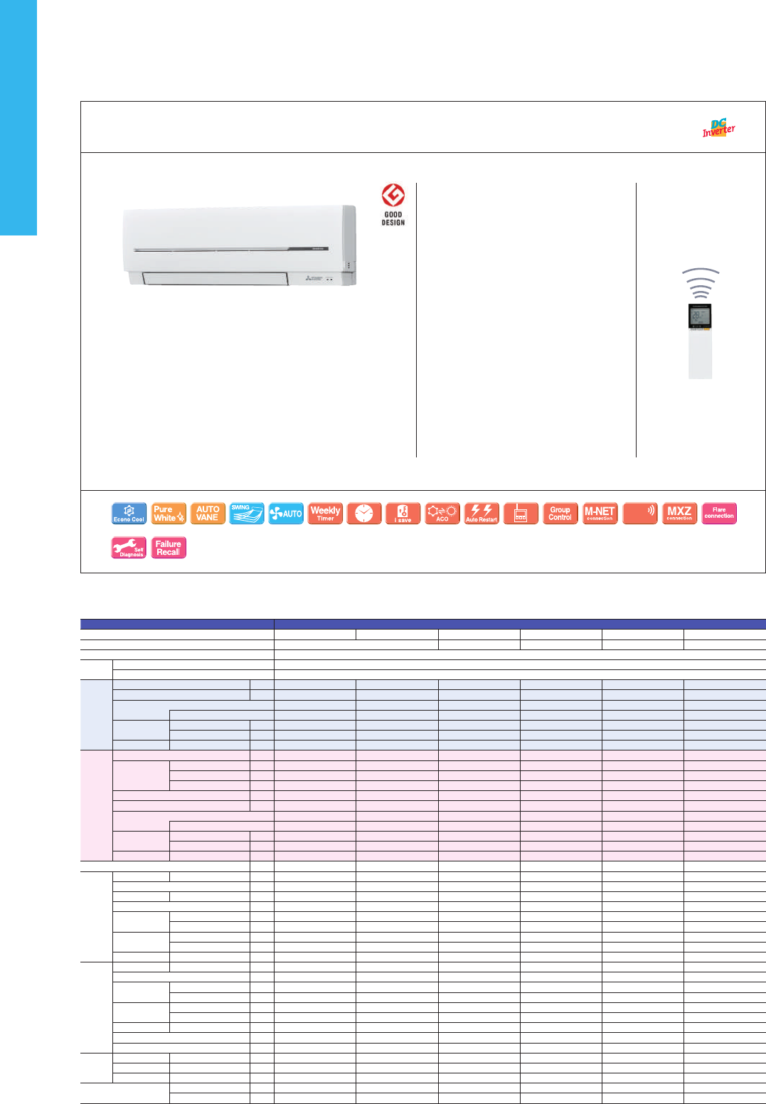
MSZ-SF15/20VA
For MXZ Connection Only
Optional
Optional Optional Optional
Wi-Fi
Interface
Indoor Unit Outdoor Unit
MSZ-S SERIES
Remote Controller
Indoor Unit
MUZ-SF50VE(H)
MUZ-GF60/71VE
MUZ-SF25/35/42VE(H)
MSZ-GF60/71VE2
Outdoor Unit
MSZ-G
SERIES
MSZ-S SERIES
Remote Controller
SEER
A
++
SCOP
A
+
Optional
Optional
Optional Optional Optional
Wi-Fi
Interface
Electrostatic
Anti-allergy
Optional
Nano
Platinum
Please fill out the requested information
Please fill out the requested information
MSZ-SF25/35/42/50VE3
41
Type Inverter Heat Pump
Indoor Unit MSZ-SF15VA MSZ-SF20VA MSZ-SF25VE2(3) MSZ-SF25VE2(3) MSZ-SF35VE2(3) MSZ-SF35VE2(3)
Outdoor Unit for MXZ connection MUZ-SF25VE MUZ-SF25VEH MUZ-SF35VE MUZ-SF35VEH
Refrigerant R410A
(*1)
Power
Supply
Source
Outdoor Power supply
Outdoor ( V / Phase / Hz )
230/Single/50
Cooling
Design load
kW
- - 2.5 2.5 3.5 3.5
Annual electricity consumption
(*2)
kWh/a
- - 116 116 171 171
SEER
(*4)
- - 7.6 7.6 7.2 7.2
Energy efficiency class
- - A
++
A
++
A
++
A
++
Capacity
Rated
kW
- - 2.5 2.5 3.5 3.5
Min-Max
kW
- - 0.9-3.4 0.9-3.4 1.1-3.8 1.1-3.8
Total Input
Rated
kW
- - 0.600 0.600 1.080 1.080
Heating
(Average
Season)
(*5)
Design load
kW
- - 2.4(-10ºC) 2.4(-10ºC) 2.9(-10ºC) 2.9(-10ºC)
Declared
Capacity
at reference design temperature
kW
- - 2.4(-10ºC) 2.4(-10ºC) 2.9(-10ºC) 2.9(-10ºC)
at bivalent temperature
kW
- - 2.4(-10ºC) 2.4(-10ºC) 2.9(-10ºC) 2.9(-10ºC)
at operation limit temperature
kW
- - 2.0(-15ºC) 1.6(-20ºC) 2.2(-15ºC) 1.6(-20ºC)
Back up heating capacity
kW
- - 0.0(-10ºC) 0.0(-10ºC) 0.0(-10ºC) 0.0(-10ºC)
Annual electricity consumption
(*2)
kWh/a
- - 764 790 923 948
SCOP
(*4)
- - 4.4 4.3 4.4 4.3
Energy efficiency class
- - A
+
A
+
A
+
A
+
Capacity
Rated
kW
- - 3.2 3.2 4.0 4.0
Min-Max
kW
- - 1.0-4.1 1.0-4.1 1.3-4.6 1.3-4.6
Total Input
Rated
kW
- - 0.780 0.780 1.030 1.030
Operating Current (Max)
A
- - 8.4 8.4 8.5 8.5
Indoor
Unit
Input
Rated
kW
0.017 0.019 0.024 0.024 0.027 0.027
Operating Current(Max)
A
0.17 0.19 0.2 0.2 0.3 0.3
Dimensions
H*W*D
mm
250-760-168 250-760-168 299-798-195 299-798-195 299-798-195 299-798-195
Weight
kg
7.7 7.7 10 10 10 10
Air Volume (SLo-Lo-
Mid-Hi-SHi
(*3)
(Dry/Wet))
Cooling
m
3
/min
3.5 - 3.9 - 4.6 - 5.5 - 6.4 3.5 - 3.9 - 4.6 - 5.5 - 6.9
3.2 - 4.1 - 5.6 - 7.2 - 9.1 3.2 - 4.1 - 5.6 - 7.2 - 9.1 3.2 - 4.1 - 5.6 - 7.2 - 9.1 3.2 - 4.1 - 5.6 - 7.2 - 9.1
Heating
m
3
/min
3.7 - 4.4 - 5.0 - 6.0 - 6.8 3.7 - 4.4 - 5.0 - 6.0 - 7.3
3.0 - 4.1 - 6.7 - 8.2 - 10.3 3.0 - 4.1 - 6.7 - 8.2 - 10.3 3.0 - 4.1 - 6.7 - 8.3 - 11.0 3.0 - 4.1 - 6.7 - 8.3 - 11.0
Sound Level (SPL)
(SLo-Lo-Mid-Hi-SHi
(*3)
)
Cooling
dB(A)
21 - 26 - 30 - 35 - 40 21 - 26 - 30 - 35 - 42
19
(*6)
- 24 - 30 - 36 - 42 19
(*6)
- 24 - 30 - 36 - 42 19
(*6)
- 24 - 30 - 36 - 42 19
(*6)
- 24 - 30 - 36 - 42
Heating
dB(A)
21 - 26 - 30 - 35 - 40 21 - 26 - 30 - 35 - 42
19
(*6)
- 24 - 34 - 39 - 45 19
(*6)
- 24 - 34 - 39 - 45 19
(*6)
- 24 - 34 - 40 - 46 19
(*6)
- 24 - 34 - 40 - 46
Sound Level (PWL)
Cooling
dB(A)
59 60 57 57 57 57
Outdoor
Unit
Dimensions
H*W*D
mm
- - 550-800-285 550-800-285 550-800-285 550-800-285
Weight
kg
- - 31 31 31 31
Air Volume
Cooling
m
3
/min
- - 31.1 31.1 35.9 35.9
Heating
m
3
/min
- - 30.7 30.7 35.9 35.9
Sound Level (SPL)
Cooling
dB(A)
- - 47 47 49 49
Heating
dB(A)
- - 48 48 50 50
Sound Level (PWL)
Cooling
dB(A)
- - 58 58 62 62
Operating Current (Max)
A
- - 8.2 8.2 8.2 8.2
Breaker Size
A
- - 10 10 10 10
Ext.
Piping
Diameter
Liquid/Gas
mm
6.35/9.52 6.35/9.52 6.35 / 9.52 6.35 / 9.52 6.35 / 9.52 6.35 / 9.52
Max.Length
Out-In
m
- - 20 20 20 20
Max.Height
Out-In
m
- - 12 12 12 12
Guaranteed Operating
Range (Outdoor)
Cooling
˚C
- - -10 ~ +46 -10 ~ +46 -10 ~ +46 -10 ~ +46
Heating
˚C
- - -15 ~ +24 -20 ~ +24 -15 ~ +24 -20 ~ +24
(*1) Refrigerant leakage contributes to climate change. Refrigerant with lower global warming potential (GWP) would contribute less to global warming than a refrigerant with higher GWP, if leaked to the atmosphere. This appliance contains a refrigerant fluid with
a GWP equal to 1975. This means that if 1 kg of this refrigerant fluid would be leaked to the atmosphere, the impact on global warming would be 1975 times higher than 1 kg of CO
2, over a period of 100 years. Never try to interfere with the refrigerant circuit
yourself or disassemble the product yourself and always ask a professional.
(*2) Energy consumption based on standard test results.Actual energy consumption will depend on how the appliance is used and where it is located.
(*3) SHi: Super High
(*4) SEER, SCOP and other related description are based on COMMISSION DELEGATED REGULATION (EU) No.626/2011. The temperature conditions for calculating SCOP are based on “Average Season”.
(*5) Please see page 47 for heating (warmer season) specifications.
(*6) For single use: only 19dB(A). For multi use (MXZ): 21dB(A).
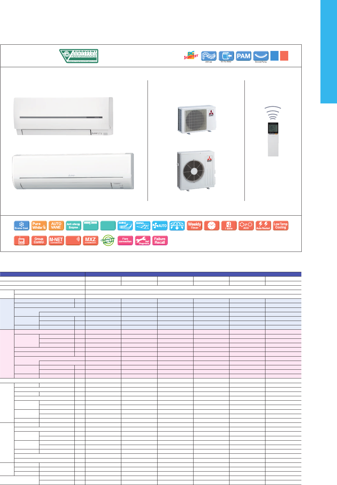
MSZ-SF15/20VA
For MXZ Connection Only
Optional
Optional Optional Optional
Wi-Fi
Interface
Indoor Unit Outdoor Unit
MSZ-S SERIES
Remote Controller
Indoor Unit
MUZ-SF50VE(H)
MUZ-GF60/71VE
MUZ-SF25/35/42VE(H)
MSZ-GF60/71VE2
Outdoor Unit
MSZ-G
SERIES
MSZ-S SERIES
Remote Controller
SEER
A
++
SCOP
A
+
Optional
Optional
Optional Optional Optional
Wi-Fi
Interface
Electrostatic
Anti-allergy
Optional
Nano
Platinum
Please fill out the requested information
Please fill out the requested information
MSZ-SF25/35/42/50VE3
Type Inverter Heat Pump
Indoor Unit MSZ-SF42VE2(3) MSZ-SF42VE2(3) MSZ-SF50VE2(3) MSZ-SF50VE2(3) MSZ-GF60VE(2) MSZ-GF71VE(2)
Outdoor Unit MUZ-SF42VE MUZ-SF42VEH MUZ-SF50VE MUZ-SF50VEH MUZ-GF60VE MUZ-GF71VE
Refrigerant R410A
(*1)
Power
Supply
Source
Outdoor Power supply
Outdoor ( V / Phase / Hz )
230/Single/50
Cooling
Design load
kW
4.2 4.2 5 5 6.1 7.1
Annual electricity consumption
(*2)
kWh/a
196 196 246 246 311 364
SEER
(*4)
7.5 7.5 7.2 7.2 6.8 6.8
Energy efficiency class
A
++
A
++
A
++
A
++
A
++
A
++
Capacity
Rated
kW
4.2 4.2 5 5 6.1 7.1
Min-Max
kW
0.8-4.5 0.8-4.5 1.4-5.4 1.4-5.4 1.4-7.5 2.0-8.7
Total Input
Rated
kW
1.340 1.340 1.660 1.660 1.790 2.130
Heating
(Average
Season)
(*5)
Design load
kW
3.8 (-10ºC) 3.8 (-10ºC) 4.2 (-10ºC) 4.2 (-10ºC) 4.6 (-10ºC) 6.7 (-10ºC)
Declared
Capacity
at reference design temperature
kW
3.8 (-10ºC) 3.8 (-10ºC) 4.2 (-10ºC) 4.2 (-10ºC) 4.6 (-10ºC) 6.7 (-10ºC)
at bivalent temperature
kW
3.8 (-10ºC) 3.8 (-10ºC) 4.2 (-10ºC) 4.2 (-10ºC) 4.6 (-10ºC) 6.7 (-10ºC)
at operation limit temperature
kW
3.4 (-15ºC) 2.2 (-20ºC) 3.4 (-15ºC) 2.3 (-20ºC) 3.7 (-15ºC) 5.4 (-15ºC)
Back up heating capacity
kW
0.0 (-10ºC) 0.0 (-10ºC) 0.0 (-10ºC) 0.0 (-10ºC) 0.0 (-10ºC) 0.0 (-10ºC)
Annual electricity consumption
(*2)
kWh/a
1215 1242 1351 1380 1489 2204
SCOP
(*4)
4.4 4.3 4.4 4.3 4.3 4.2
Energy efficiency class
A
+
A
+
A
+
A
+
A
+
A
+
Capacity
Rated
kW
5.4 5.4 5.8 5.8 6.8 8.1
Min-Max
kW
1.3-6.0 1.3-6.0 1.4-7.3 1.4-7.3 2.0-9.3 2.2-9.9
Total Input
Rated
kW
1.580 1.58 1.7 1.7 1.81 2.23
Operating Current (Max)
A
9.5 9.5 12.3 12.3 14.5 16.6
Indoor
Unit
Input
Rated
kW
0.027 0.027 0.035 0.035 0.062 0.058
Operating Current(Max)
A
0.3 0.3 0.3 0.3 0.5 0.5
Dimensions
H*W*D
mm
299-798-195 299-798-195 299-798-195 299-798-195 325-1100-238 325-1100-238
Weight
kg
10 10 10 10 16 16
Air Volume (SLo-Lo-
Mid-Hi-SHi
(*3)
(Dry/Wet))
Cooling
m
3
/min 4.7 - 5.8 - 6.7 - 7.9 - 9.1 4.7 - 5.8 - 6.7 - 7.9 - 9.1 5.1 - 6.2 - 7.0 - 8.2 - 9.9 5.1 - 6.2 - 7.0 - 8.2 - 9.9 9.8-11.3-13.4-15.6-18.3 9.7-11.5-13.3-15.4-17.8
Heating
m
3
/min 4.7 - 5.8 - 7.2 - 9.1 - 11.4 4.7 - 5.8 - 7.2 - 9.1 - 11.4 5.1 - 6.4 - 8.0 - 9.8 - 12.0 5.1 - 6.4 - 8.0 - 9.8 - 12.0 9.8-11.3-13.4-15.6-18.3 10.2-11.5-13.3-15.4-17.8
Sound Level (SPL)
(SLo-Lo-Mid-Hi-SHi
(*3)
)
Cooling
dB(A)
26
(*6)
- 31 - 34 - 38 - 42 26
(*6)
- 31 - 34 - 38 - 42 28
(*7)
- 33 - 36 - 40 - 45 28
(*7)
- 33 - 36 - 40 - 45
29 - 37 -41 - 45 - 49 30 - 37 - 41 - 45 - 49
Heating
dB(A)
26
(*6)
- 31 - 36 - 42 - 47 26
(*6)
- 31 - 36 - 42 - 47 28
(*7)
- 33 - 38 - 43 - 49 28
(*7)
- 33 - 38 - 43 - 49
29 - 37 - 41 - 45 - 49 30 - 37 - 41 - 45 - 49
Sound Level (PWL)
Cooling
dB(A)
57 57 58 58 65 65
Outdoor
Unit
Dimensions
H*W*D
mm
550-800-285 550-800-285 880-840-330 880-840-330 880-840-330 880-840-330
Weight
kg
35 35 55 55 50 53
Air Volume
Cooling
m
3
/min
35.2 35.2 44.6 44.6 49.2 50.1
Heating
m
3
/min
33.6 33.6 44.6 44.6 49.2 48.2
Sound Level (SPL)
Cooling
dB(A)
50 50 52 52 55 55
Heating
dB(A)
51 51 52 52 55 55
Sound Level (PWL)
Cooling
dB(A)
63 63 65 65 65 65
Operating Current (Max)
A
9.2 9.2 12 12 14 16.1
Breaker Size
A
10 10 16 16 20 20
Ext.
Piping
Diameter
Liquid/Gas
mm
6.35 / 9.52 6.35 / 9.52 6.35 / 12.7 6.35 / 12.7 6.35/15.88 9.52/15.88
Max.Length
Out-In
m
20 20 30 30 30 30
Max.Height
Out-In
m
12 12 15 15 15 15
Guaranteed Operating
Range (Outdoor)
Cooling
˚C
-10 ~ +46 -10 ~ +46 -10 ~ +46 -10 ~ +46 -10 ~ +46 -10 ~ +46
Heating
˚C
-15 ~ +24 -20 ~ +24 -15 ~ +24 -20 ~ +24 -15 ~ +24 -15 ~ +24
(*1) Refrigerant leakage contributes to climate change. Refrigerant with lower global warming potential (GWP) would contribute less to global warming than a refrigerant with higher GWP, if leaked to the atmosphere. This appliance contains a refrigerant fluid with
a GWP equal to 1975. This means that if 1 kg of this refrigerant fluid would be leaked to the atmosphere, the impact on global warming would be 1975 times higher than 1 kg of CO
2, over a period of 100 years. Never try to interfere with the refrigerant circuit
yourself or disassemble the product yourself and always ask a professional.
(*2) Energy consumption based on standard test results.Actual energy consumption will depend on how the appliance is used and where it is located.
(*3) SHi: Super High
(*4) SEER, SCOP and other related description are based on COMMISSION DELEGATED REGULATION (EU) No.626/2011. The temperature conditions for calculating SCOP are based on “Average Season”.
(*5) Please see page 47 for heating (warmer season) specifications.
(*6) For single use: only 26dB(A), For multi use (MXZ): 28dB(A).
(*7) For single use: only 28dB(A), For multi use (MXZ): 30dB(A).
42
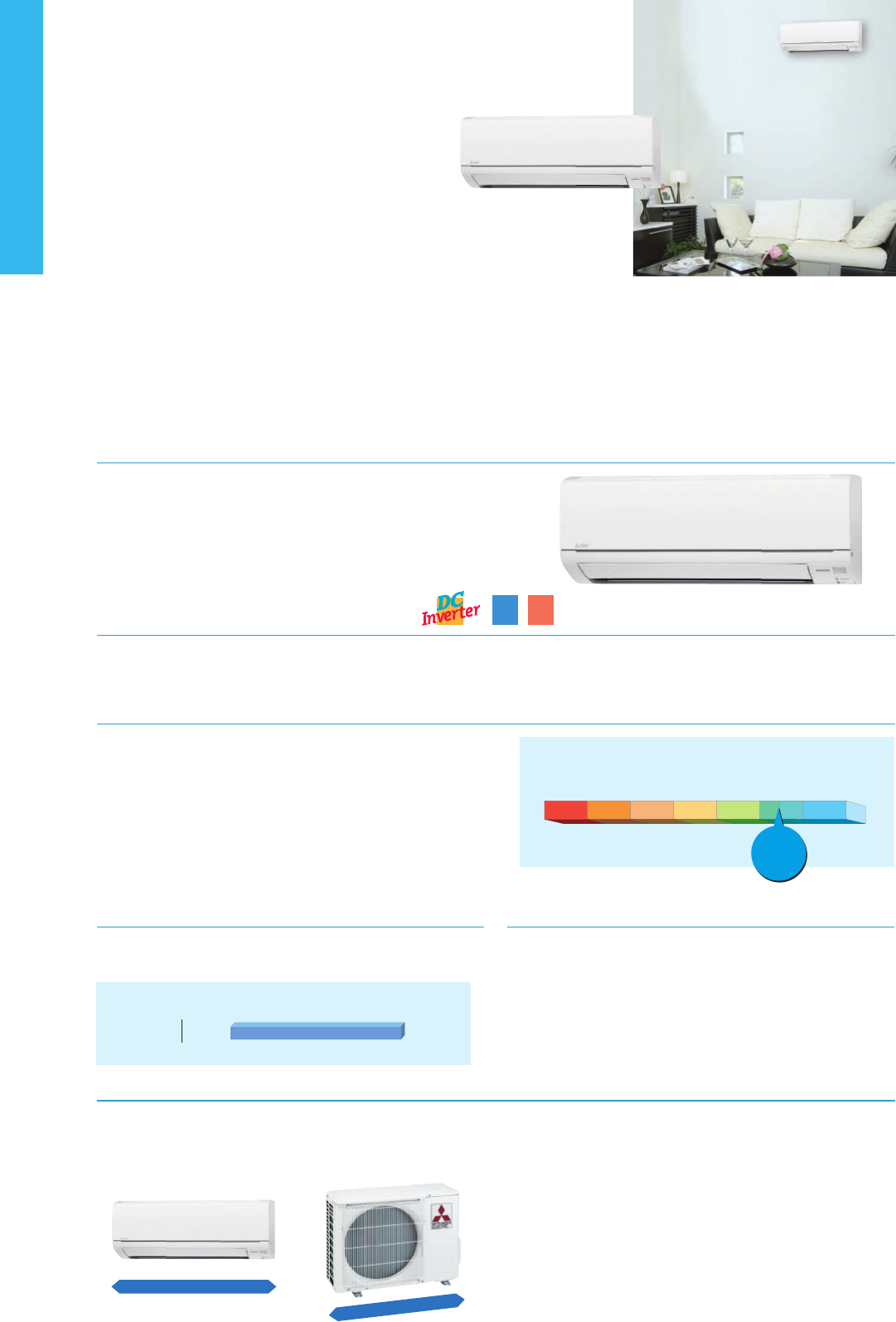
MSZ-D
SERIES
Compact, high-performance indoor and outdoor units and advanced inverter technologies
provide superior energy savings and comfort in all rooms.
Stylish Design with Flat Panel Front
A stylish at panel design is employed for the front of the indoor unit.
The simple look matches room aesthetics.
Silent Operation
Quiet, relaxing space is within reach. Operational noise is a low 22dB (25/35
classes). Operation is so silent you might even forget the air conditioner is on.
Wide operating range
In order to satisfy a larger type of applications, operating range in
cooling mode is possible until -10 °C of outdoor temperature.
Multi-functional connectors added
Thanks to built-in multi-functional connectors, MSZ-DM series can be
connected to several accessories. This allows unit control through
wired remote controller, M-net connection and MELCloud
compatibility.
Compact Units
The widths of both indoor and outdoor units are compact, making installa-
tion in smaller, tighter spaces possible.
Advanced Inverter Control –
Ecient Operation All the Time
Mitsubishi Electric’s cutting-edge inverter technologies are adopted to provide automatic adjustment of operation load according to need. This reduces
excessive consumption of electricity, and thereby realises an Energy Rank “A+” rating for both 25 and 35 classes.
.
● Noise Level
10dB40dB60dB80dB
Subway car
interior
Quiet passenger
car interior
(40km/h)
Library interior
Human
hearing limits
(Extremely quiet)
*MSZ-HJ25/35VA
Sound of
rustling leaves
22dB
*
Only
SEER
A
+
SCOP
A
+
● Operating Range (Cooling)
MUZ-DM
-10°C +46°C
MSZ-DM25/35VA
SEER
A
+
SCOP
A
+
Indoor Unit Outdoor Unit
Remote
Controller
MSZ-D SERIES
MUZ-DM25/35VA
Please fill out the requested information
Please fill out the requested information
50/60/7150/60/71 50/60/71
Only 699mm widt
h
Indoor Unit: MSZ-DM25/35VA
Outdoor Unit: MUZ-DM25/35VA
Only 799mm width
Optional
An in-company
investigation
MUZ
MUZ-
M
M
M
MUZ
M
MUZ-
MUZ-
MUZ
M
MUZ
MUZ
MUZ
M
MU
MUZ
MUZ
MUZ-
MUZ
MU
MUZ
MUZ-
MUZ-
Z
Z
MUZ
Z
MUZ
MUZ-
Z
Z
UZ-
MUZ-
-
UZ-
M
MU
MU
MUZ
MU
U
U
MU
U
Z
Z
-
M
MUZ
MUZ-
M
MUZ
U
UZ
Z-
Z
Z
Z-
UZ-
MU
MU
UZ
Z
MU
M
U
MU
U
U
UZ
Z
MUZ-
UZ
-
Z-
Z-
U
U
MU
U
Z
Z
Z-
MU
M
M
M
U
U
U
Z
Z
UU
Z
Z
MU
U
M
MU
U
Z
Z
-
MUZ
MUZ
M
M
UZ
UZ-
MUZ
UZ
MUZ
U
MUZ
Z
Z
Z
UZ
-
-
MUZ
MUZ-
MU
U
U
U
UZ-
U
UZ
U
Z-
-
-
UZ-
MU
M
M
MU
U
U
U
Z
Z
Z
Z
Z
M
MUZ
U
U
Z
Z
MU
MUZ
M
U
Z
U
DM
DM
D
DM
DM
DM
D
DM
DM2
DM
M2
DM
DM2
DM
M
DM
M
M
M2
M
M
M2
DM2
DM2
M25
2
2
25
2
2
2
25
M25
5
M
2
2
DM2
5
D
D
2
2
DM2
2
2
2
M2
M2
2
2
M
M
2
2
2
2
25
2
DM2
2
2
DM2
M
2
2
2
2
2
D
M2
2
D
M
2
2
2
2
M
2
2
2
D
DM
D
D
DM
M
M
M
M
2
2
2
2
2
D
D
D
D
D
D
D
D
DM
D
M
M
DM
M
DM
M
DM
M
DM
M2
2
DM2
2
2
5
D
D
D
D
D
D
D
D
M2
M
M
M2
M
M
M
2
2
2
2
D
D
DM
D
D
D
DM2
M
M
M
M
M
M
M
2
2
2
2
2
2
2
D
D
M2
M
M
2
2
D
D
2
2
DM2
2
D
D
D
D
M
M
M
M
M
2
2
D
M
M
/35V
/35V
A
A
MSZ-DM25/35VA MUZ-DM25/35VA
Wi-Fi
Interface
43
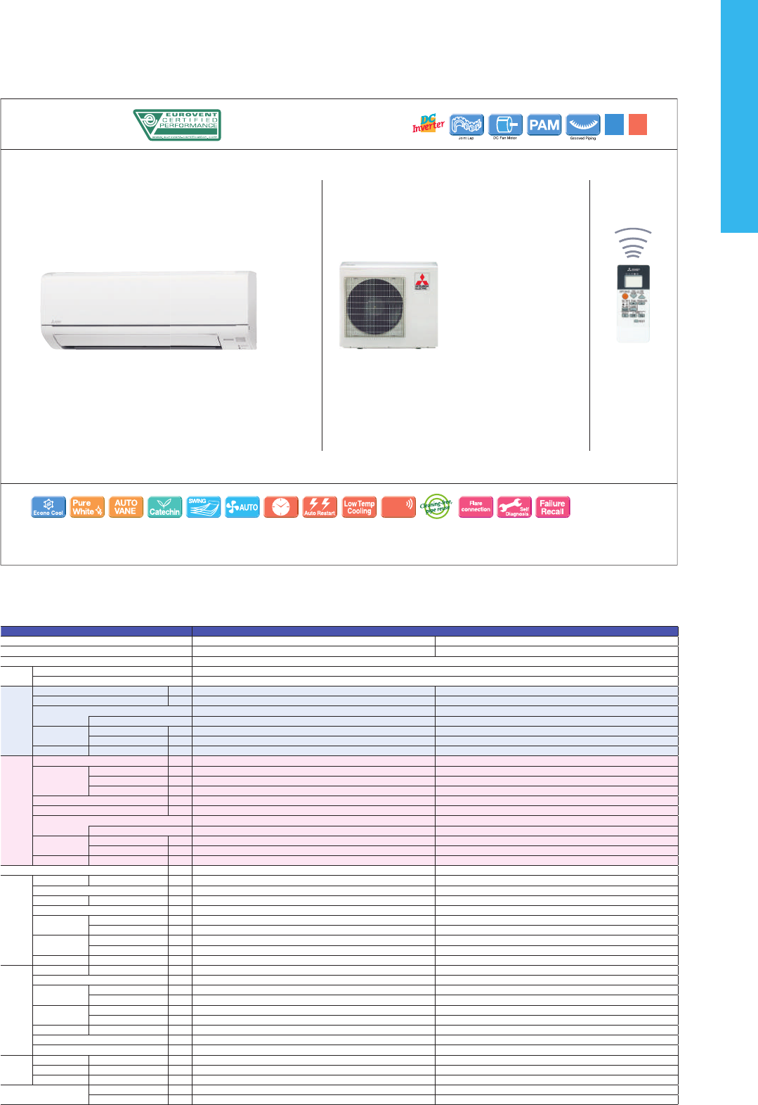
MSZ-D
SERIES
Compact, high-performance indoor and outdoor units and advanced inverter technologies
provide superior energy savings and comfort in all rooms.
Stylish Design with Flat Panel Front
A stylish at panel design is employed for the front of the indoor unit.
The simple look matches room aesthetics.
Silent Operation
Quiet, relaxing space is within reach. Operational noise is a low 22dB (25/35
classes). Operation is so silent you might even forget the air conditioner is on.
Wide operating range
In order to satisfy a larger type of applications, operating range in
cooling mode is possible until -10 °C of outdoor temperature.
Multi-functional connectors added
Thanks to built-in multi-functional connectors, MSZ-DM series can be
connected to several accessories. This allows unit control through
wired remote controller, M-net connection and MELCloud
compatibility.
Compact Units
The widths of both indoor and outdoor units are compact, making installa-
tion in smaller, tighter spaces possible.
Advanced Inverter Control –
Ecient Operation All the Time
Mitsubishi Electric’s cutting-edge inverter technologies are adopted to provide automatic adjustment of operation load according to need. This reduces
excessive consumption of electricity, and thereby realises an Energy Rank “A” rating for 25/35 classes and “A
+
” for 50/60/71 classes.
● Noise Level
10dB40dB60dB80dB
Subway car
interior
Quiet passenger
car interior
(40km/h)
Library interior
Human
hearing limits
(Extremely quiet)
*MSZ-HJ25/35VA
Sound of
rustling leaves
22dB
*
Only
SEER
A
+
SCOP
A
+
● Operating Range (Cooling)
MUZ-DM
-10°C +43°C
MSZ-DM25/35VA
SEER
A
+
SCOP
A
+
Indoor Unit Outdoor Unit
Remote
Controller
MSZ-D SERIES
MUZ-DM25/35VA
Please fill out the requested information
Please fill out the requested information
50/60/7150/60/71 50/60/71
Only 699mm widt
h
Indoor Unit: MSZ-DM25/35VA
Outdoor Unit: MUZ-DM25/35VA
Only 799mm width
Optional
An in-company
investigation
MUZ
MUZ-
M
M
M
MUZ
M
MUZ-
MUZ-
MUZ
M
MUZ
MUZ
MUZ
M
MU
MUZ
MUZ
MUZ-
MUZ
MU
MUZ
MUZ-
MUZ-
Z
Z
MUZ
Z
MUZ
MUZ-
Z
Z
UZ-
MUZ-
-
UZ-
M
MU
MU
MUZ
MU
U
U
MU
U
Z
Z
-
M
MUZ
MUZ-
M
MUZ
U
UZ
Z-
Z
Z
Z-
UZ-
MU
MU
UZ
Z
MU
M
U
MU
U
U
UZ
Z
MUZ-
UZ
-
Z-
Z-
U
U
MU
U
Z
Z
Z-
MU
M
M
M
U
U
U
Z
Z
U
U
Z
Z
MU
U
M
MU
U
Z
Z
-
MUZ
MUZ
M
M
UZ
UZ-
MUZ
UZ
MUZ
U
MUZ
Z
Z
Z
UZ
-
-
MUZ
MUZ-
MU
U
U
U
UZ-
U
UZ
U
Z-
-
-
UZ-
MU
M
M
MU
U
U
U
Z
Z
Z
Z
Z
M
MUZ
U
U
Z
Z
MU
MUZ
M
U
Z
U
DM
DM
D
DM
DM
DM
D
DM
DM2
DM
M2
DM
DM2
DM
M
DM
M
M
M2
M
M
M2
DM2
DM2
M25
2
2
25
2
2
2
25
M25
5
M
2
2
DM2
5
D
D
2
2
DM2
2
2
2
M2
M2
2
2
M
M
2
2
2
2
25
2
DM2
2
2
DM2
M
2
2
2
2
2
D
M2
2
D
M
2
2
2
2
M
2
2
2
D
DM
D
D
DM
M
M
M
M
2
2
2
2
2
D
D
D
D
D
D
D
D
DM
D
M
M
DM
M
DM
M
DM
M
DM
M2
2
DM2
2
2
5
D
D
D
D
D
D
D
D
M2
M
M
M2
M
M
M
2
2
2
2
D
D
DM
D
D
D
DM2
M
M
M
M
M
M
M
2
2
2
2
2
2
2
D
D
M2
M
M
2
2
D
D
2
2
DM2
2
D
D
D
D
M
M
M
M
M
2
2
D
M
M
/35V
/35V
A
A
MSZ-DM25/35VA MUZ-DM25/35VA
Wi-Fi
Interface
44
Type Inverter Heat Pump
Indoor Unit MSZ-DM25VA MSZ-DM35VA
Outdoor Unit MUZ-DM25VA MUZ-DM35VA
Refrigerant R410A
(*1)
Power
Supply
Source
Indoor Power supply
Outdoor ( V / Phase / Hz )
230V/Single/50Hz
Cooling
Design load
kW
2.5 3.1
Annual electricity consumption
(*2)
kWh/a
151 193
SEER
(*4)
5.8 5.7
Energy efficiency class
A+ A+
Capacity
Rated
kW
2.5 3.15
Min-Max
kW
1.3 - 3.0 1.4 - 3.5
Total Input
Rated
kW
0.730 1.040
Heating
(Average
Season)
(*5)
Design load
kW
1.9 (-10ºC) 2.4 (-10ºC)
Declared
Capacity
at reference design temperature
kW
1.9 (-10ºC) 2.4 (-10ºC)
at bivalent temperature
kW
1.9 (-10ºC) 2.4 (-10ºC)
at operation limit temperature
kW
1.9 (-10ºC) 2.4 (-10ºC)
Back up heating capacity
kW
0.0 (-10ºC) 0.0 (-10ºC)
Annual electricity consumption
(*2)
kWh/a
649 781
SCOP
(*4)
4.1 4.5
Energy efficiency class
A+ A+
Capacity
Rated
kW
3.15 3.6
Min-Max
kW
0.9 - 3.5 1.1 - 4.1
Total Input
Rated
kW
0.870 0.995
Operating Current (Max)
A
5.8 6.5
Indoor
Unit
Input
Rated
kW
NA NA
Operating Current(Max)
A
NA NA
Dimensions
H*W*D
mm
290-799-232 290-799-232
Weight
kg
9 9
Air Volume (SLo-Lo-
Mid-Hi-SHi
(*3)
(Dry/Wet))
Cooling
m
3
/min
3.8 - 5.5 - 7.3 - 9.5 3.8 - 5.7 - 7.8 - 10.9
Heating
m
3
/min
3.5 - 5.5 - 7.5 - 10.0 3.5 - 5.5 - 7.5 - 10.3
Sound Level (SPL)
(SLo-Lo-Mid-Hi-SHi
(*3)
)
Cooling
dB(A)
22 - 30 - 37 - 43 22 - 31 - 38 - 45
Heating
dB(A)
23 - 30 - 37 - 43 23 - 30 - 37 - 44
Sound Level (PWL)
Cooling
dB(A)
57 60
Outdoor
Unit
Dimensions
H*W*D
mm
538-699-249 538-699-249
Weight
kg
24 25
Air Volume
Cooling
m
3
/min
31.5 31.5
Heating
m
3
/min
31.5 31.5
Sound Level (SPL)
Cooling
dB(A)
50 51
Heating
dB(A)
50 51
Sound Level (PWL)
Cooling
dB(A)
63 64
Operating Current (Max)
A
5.8 6.5
Breaker Size
A
10 10
Ext.
Piping
Diameter
Liquid/Gas
mm
6.35/9.52 6.35/9.52
Max.Length
Out-In
m
20 20
Max.Height
Out-In
m
12 12
Guaranteed Operating
Range (Outdoor)
Cooling
˚C
-10 ~ +46 -10 ~ +46
Heating
˚C
-10 ~ +24 -10 ~ +24
(*1) Refrigerant leakage contributes to climate change. Refrigerant with lower global warming potential (GWP) would contribute less to global warming than a refrigerant with higher GWP, if leaked to the atmosphere. This appliance contains a refrigerant fluid with
a GWP equal to 1975. This means that if 1 kg of this refrigerant fluid would be leaked to the atmosphere, the impact on global warming would be 1975 times higher than 1 kg of CO
2, over a period of 100 years. Never try to interfere with the refrigerant circuit
yourself or disassemble the product yourself and always ask a professional.
(*2) Energy consumption based on standard test results.Actual energy consumption will depend on how the appliance is used and where it is located.
(*3) SHi: Super High
(*4) SEER, SCOP and other related description are based on COMMISSION DELEGATED REGULATION (EU) No.626/2011. The temperature conditions for calculating SCOP are based on “Average Season”.
(*5) Please see page 47 for heating (warmer season) specifications.
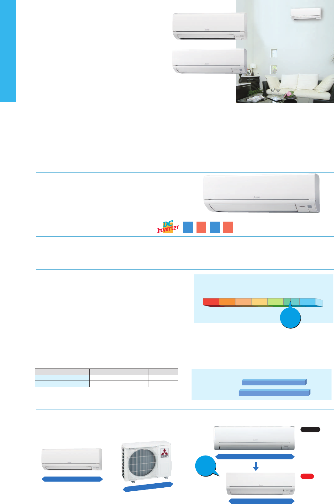
MSZ-H
SERIES
Compact, high-performance indoor and outdoor units and advanced inverter technologies
provide superior energy savings and comfort in all rooms.
Stylish Design with Flat Panel Front
A stylish at panel design is employed for the front of the indoor unit.
The simple look matches room aesthetics.
Silent Operation
Quiet, relaxing space is within reach. Operational noise is a low 22dB (25/35
classes). Operation is so silent you might even forget the air conditioner is on.
Long Piping Length
Compared to previous models, the piping length is signicantly
increased, further enhancing the ease and exibility of installation.
Operating Range
As a result of an extended operating range in cooling, these models
accommodate a wider range of usage environments and applications
than previous models.
Compact Units
The widths of both indoor and outdoor units are compact, making installa-
tion in smaller, tighter spaces possible.
Compared to previous models, width is down by 16%.
Advanced Inverter Control –
Ecient Operation All the Time
Mitsubishi Electric’s cutting-edge inverter technologies are adopted to provide automatic adjustment of operation load according to need. This reduces
excessive consumption of electricity, and thereby realises an Energy Rank “A” rating for 25/35 classes and “A
+
” for 50/60/71 classes.
SEER
A
SCOP
A
● Noise Level
10dB40dB60dB80dB
Subway car
interior
Quiet passenger
car interior
(40km/h)
Library interior
Human
hearing limits
(Extremely quiet)
*MSZ-HJ25/35VA
Sound of
rustling leaves
22dB
*
Only
25/35 25/35
SEER
A
+
SCOP
A
+
50/60/71 50/60/71
MSZ-HJ25/35/50VA
● Operating Range (Cooling)
MUZ-HC
MUZ-HJ
+18°C +43°C
+15°C +46°C
Max piping length
Max piping height dierence
MSZ-HJ60/71
30m
15m
MSZ-HJ25/35/50
20m
12m
MSZ-HC
10m
5m
MSZ-HJ60/71VA
SEER
A
+
SCOP
A
+
Indoor Unit Outdoor Unit
Remote
Controller
MSZ-H SERIES
MSZ-HJ25/35/50VA
MSZ-HJ60/71VA
MUZ-HJ25/35VA MUZ-HJ50VA
MUZ-HJ60/71VA
Please fill out the requested information
Please fill out the requested information
50/60/7150/60/71 50/60/71
16%
Down
Only 699mm widt
h
Indoor Unit: MSZ-HJ25/35/50VA
Outdoor Unit: MUZ-HJ25/35VA Indoor Unit:
MSZ-GF60/71VE
1100mm
923mm
Only 799mm width
Optional
Previous
Indoor Unit:
MSZ-HJ60/71VA
New
An in-company
investigation
45
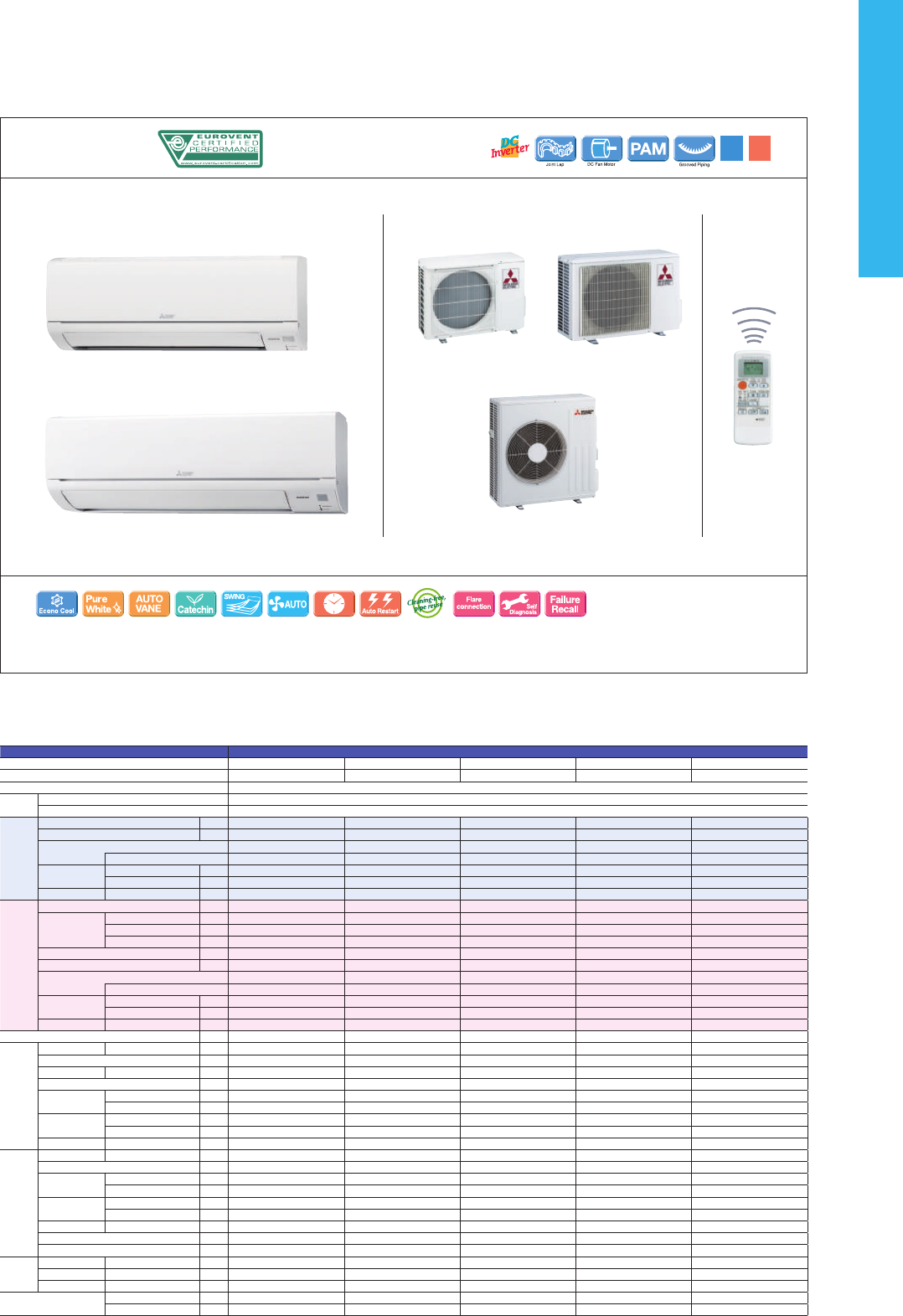
MSZ-H
SERIES
Compact, high-performance indoor and outdoor units and advanced inverter technologies
provide superior energy savings and comfort in all rooms.
Stylish Design with Flat Panel Front
A stylish at panel design is employed for the front of the indoor unit.
The simple look matches room aesthetics.
Silent Operation
Quiet, relaxing space is within reach. Operational noise is a low 22dB (25/35
classes). Operation is so silent you might even forget the air conditioner is on.
Long Piping Length
Compared to previous models, the piping length is signicantly
increased, further enhancing the ease and exibility of installation.
Operating Range
As a result of an extended operating range in cooling, these models
accommodate a wider range of usage environments and applications
than previous models.
Compact Units
The widths of both indoor and outdoor units are compact, making installa-
tion in smaller, tighter spaces possible.
Compared to previous models, width is down by 16%.
Advanced Inverter Control –
Ecient Operation All the Time
Mitsubishi Electric’s cutting-edge inverter technologies are adopted to provide automatic adjustment of operation load according to need. This reduces
excessive consumption of electricity, and thereby realises an Energy Rank “A” rating for 25/35 classes and “A
+
” for 50/60/71 classes.
SEER
A
SCOP
A
● Noise Level
10dB40dB60dB80dB
Subway car
interior
Quiet passenger
car interior
(40km/h)
Library interior
Human
hearing limits
(Extremely quiet)
*MSZ-HJ25/35VA
Sound of
rustling leaves
22dB
*
Only
25/35 25/35
SEER
A
+
SCOP
A
+
50/60/71 50/60/71
MSZ-HJ25/35/50VA
● Operating Range (Cooling)
MUZ-HC
MUZ-HJ
+18°C +43°C
+15°C +46°C
Max piping length
Max piping height dierence
MSZ-HJ60/71
30m
15m
MSZ-HJ25/35/50
20m
12m
MSZ-HC
10m
5m
MSZ-HJ60/71VA
SEER
A
+
SCOP
A
+
Indoor Unit Outdoor Unit
Remote
Controller
MSZ-H SERIES
MSZ-HJ25/35/50VA
MSZ-HJ60/71VA
MUZ-HJ25/35VA MUZ-HJ50VA
MUZ-HJ60/71VA
Please fill out the requested information
Please fill out the requested information
50/60/7150/60/71 50/60/71
16%
Down
Only 699mm widt
h
Indoor Unit: MSZ-HJ25/35/50VA
Outdoor Unit: MUZ-HJ25/35VA Indoor Unit:
MSZ-GF60/71VE
1100mm
923mm
Only 799mm width
Optional
Previous
Indoor Unit:
MSZ-HJ60/71VA
New
An in-company
investigation
46
Type Inverter Heat Pump
Indoor Unit MSZ-HJ25VA MSZ-HJ35VA MSZ-HJ50VA MSZ-HJ60VA MSZ-HJ71VA
Outdoor Unit MUZ-HJ25VA MUZ-HJ35VA MUZ-HJ50VA MUZ-HJ60VA MUZ-HJ71VA
Refrigerant R410A
(*1)
Power
Supply
Source
Indoor Power supply
Outdoor ( V / Phase / Hz )
230V/Single/50Hz
Cooling
Design load
kW
2.5 3.1 5.0 6.1 7.1
Annual electricity consumption
(*2)
kWh/a
171 212 292 354 441
SEER
(*4)
5.1 5.1 6.0 6.0 5.6
Energy efficiency class
A A A
+
A
+
A
+
Capacity
Rated
kW
2.5 3.15 5.0 6.1 7.1
Min-Max
kW
1.3 - 3.0 1.4 - 3.5 1.3 - 5.0 1.7 - 7.1 1.8 - 7.1
Total Input
Rated
kW
0.730 1.040 2.050 1.900 2.330
Heating
(Average
Season)
(*5)
Design load
kW
1.9 (-10ºC) 2.4 (-10ºC) 3.8 (-10ºC) 4.6 (-10ºC) 5.4 (-10ºC)
Declared
Capacity
at reference design temperature
kW
1.9 (-10ºC) 2.4 (-10ºC) 3.8 (-10ºC) 4.6 (-10ºC) 5.4 (-10ºC)
at bivalent temperature
kW
1.9 (-10ºC) 2.4 (-10ºC) 3.8 (-10ºC) 4.6 (-10ºC) 5.4 (-10ºC)
at operation limit temperature
kW
1.9 (-10ºC) 2.4 (-10ºC) 3.8 (-10ºC) 4.6 (-10ºC) 5.4 (-10ºC)
Back up heating capacity
kW
0.0 (-10ºC) 0.0 (-10ºC) 0.0 (-10ºC) 0.0 (-10ºC) 0.0 (-10ºC)
Annual electricity consumption
(*2)
kWh/a
698 885 1267 1544 1854
SCOP
(*4)
3.8 3.8 4.2 4.1 4.0
Energy efficiency class
A A A
+
A
+
A
+
Capacity
Rated
kW
3.15 3.6 5.4 6.8 8.1
Min-Max
kW
0.9 - 3.5 1.1 - 4.1 1.4 - 6.5 1.5 - 8.4 1.5 - 8.5
Total Input
Rated
kW
0.870 0.995 1.480 1.970 2.440
Operating Current (Max)
A
5.8 6.5 9.8 12.5 12.5
Indoor
Unit
Input
Rated
kW
0.020 0.021 0.037 0.055 0.055
Operating Current(Max)
A
0.3 0.3 0.4 0.5 0.5
Dimensions
H*W*D
mm
290-799-232 290-799-232 290-799-232 305-923-250 305-923-250
Weight
kg
9 9 9 13 13
Air Volume (SLo-Lo-
Mid-Hi-SHi
(*3)
(Dry/Wet))
Cooling
m
3
/min
3.8 - 5.5 - 7.3 - 9.5 3.8 - 5.7 - 7.8 - 10.9 6.3 - 9.1 - 11.1 - 12.9 9.3 - 12.2 - 15.0 - 19.9 10.0 - 12.2 - 15.0 - 19.9
Heating
m
3
/min
3.5 - 5.5 - 7.5 - 10.0 3.5 - 5.5 - 7.5 - 10.3 6.1 - 8.3 - 11.1 - 14.3 9.4 - 12.5 - 16.0 - 19.9 10.3 - 12.7 - 16.4 - 19.9
Sound Level (SPL)
(SLo-Lo-Mid-Hi-SHi
(*3)
)
Cooling
dB(A)
22 - 30 - 37 - 43 22 - 31 - 38 - 45 28 - 36 - 40 - 45 31 - 38 - 44 - 50 33 - 38 - 44 - 50
Heating
dB(A)
23 - 30 - 37 - 43 23 - 30 - 37 - 44 27 - 34 - 41 - 47 31 - 38 - 44 - 49 33 - 38 - 44 - 49
Sound Level (PWL)
Cooling
dB(A)
57 60 60 65 65
Outdoor
Unit
Dimensions
H*W*D
mm
538-699-249 538-699-249 550-800-285 880-840-330 880-840-330
Weight
kg
24 25 36 55 55
Air Volume
Cooling
m
3
/min
31.5 31.5 36.3 47.9 49.3
Heating
m
3
/min
31.5 31.5 34.8 47.9 47.9
Sound Level (SPL)
Cooling
dB(A)
50 50 50 55 55
Heating
dB(A)
50 50 51 55 55
Sound Level (PWL)
Cooling
dB(A)
63 64 64 65 66
Operating Current (Max)
A
5.5 6.2 9.4 12 12
Breaker Size
A
10 10 12 16 16
Ext.
Piping
Diameter
Liquid/Gas
mm
6.35/9.52 6.35/9.52 6.35/12.7 6.35/15.88 9.52/15.88
Max.Length
Out-In
m
20 20 20 30 30
Max.Height
Out-In
m
12 12 12 15 15
Guaranteed Operating
Range (Outdoor)
Cooling
˚C
+15 ~ +46 +15 ~ +46 +15 ~ +46 +15 ~ +46 +15 ~ +46
Heating
˚C
-10 ~ +24 -10 ~ +24 -10 ~ +24 -10 ~ +24 -10 ~ +24
(*1) Refrigerant leakage contributes to climate change. Refrigerant with lower global warming potential (GWP) would contribute less to global warming than a refrigerant with higher GWP, if leaked to the atmosphere. This appliance contains a refrigerant fluid with
a GWP equal to 1975. This means that if 1 kg of this refrigerant fluid would be leaked to the atmosphere, the impact on global warming would be 1975 times higher than 1 kg of CO
2, over a period of 100 years. Never try to interfere with the refrigerant circuit
yourself or disassemble the product yourself and always ask a professional.
(*2) Energy consumption based on standard test results.Actual energy consumption will depend on how the appliance is used and where it is located.
(*3) SHi: Super High
(*4) SEER, SCOP and other related description are based on COMMISSION DELEGATED REGULATION (EU) No.626/2011. The temperature conditions for calculating SCOP are based on “Average Season”.
(*5) Please see page 47 for heating (warmer season) specifications.
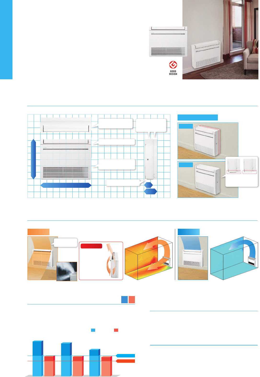
MFZ
SERIES
High Capacity, Energy Savings and a Design in Harmony with Living Spaces
Raise the Value of Your Room to the Next Level.
*The downward airflow is also possible as well as heating.
Cooling Heating
SCOP
4.5
SEER
8.1
SCOP
4.4
MFZ-KJ25VE MFZ-KJ35VE
SEER
6.5
SCOP
4.3
MFZ-KJ50VE
SEER
8.5
SEER Rank A(5.1)
SCOP Rank A(3.8)
Excellent Energy-saving Performance
SEER A
+++
(25) and SCOP A
+
(25/35/50) ratings have been achieved through
development focusing on compliance with European energy-related
product (ErP) regulations.
Weekly Timer
(Introduced in response to market demand)
Temperature settings and On/O control can be managed over a period
of one week using the Weekly Timer. Up to eight setting patterns per cal-
endar day are possible.
Trouble-free Installation and Maintenance
Using the original installation plate that comes as standard equipment,
installation of the unit is a snap. Levelling adjusters are provided, pre-
venting damage to the wall. Generous pipe length (20–30 metres) is
provided, so there is no need to worry about distance to the outdoor
unit. All units are equipped with an automatic self-diagnostics function
as well. Simply access the trouble log recall mode for instant trouble-
shooting.
Operating Current (Max)
Ext.
Piping
Guaranteed Operating Range
[Outdoor]
kW
kWh/a
kW
kW
kW
kW
kW
kW
kW
kW
kWh/a
kW
kW
kW
A
kW
A
mm
kg
m3/min
m3/min
dB(A)
dB(A)
dB(A)
mm
kg
m3/min
m3/min
dB(A)
dB(A)
dB(A)
A
A
mm
m
m
o
C
o
C
MFZ-KJ25VE(2)
MUFZ-KJ25VE
R410A
(*1)
2.5
102
8.5
A
+++
2.5
0.5 - 3.4
0.540
3.4(-10
o
C)
3.4(-10
o
C)
3.4(-10
o
C)
2.4(-15
o
C)
0.0(-10
o
C)
1059
4.5
A
+
3.4
1.2 - 4.6
0.770
9.4
0.016
0.17
600-750-215
15
3.9 - 4.9 - 5.9 - 7.1 - 8.2
3.9 - 5.1 - 6.2 - 7.7 - 9.7
20 - 25 - 30 - 35 - 39
19 - 25 - 30 - 35 - 41
49
550-800-285
37
31.3
33.6
46
51
59
9.2
10
6.35/9.52
20
12
-10 ~ +46
-15 ~ +24
MFZ-KJ35VE(2)
MUFZ-KJ35VE
R410A
(*1)
3.5
150
8.1
A
++
3.5
0.5 - 3.7
0.940
3.5(-10
o
C)
3.5(-10
o
C)
3.5(-10
o
C)
2.9(-15
o
C)
0.0(-10
o
C)
1110
4.4
A
+
4.3
1.2 - 5.5
1.100
9.4
0.016
0.17
600-750-215
15
3.9 - 4.9 - 5.9 - 7.1 - 8.2
3.9 - 5.1 - 6.2 - 7.7 - 9.7
20 - 25 - 30 - 35 - 39
19 - 25 - 30 - 35 - 41
50
550-800-285
37
31.3
33.6
47
51
60
9.2
10
6.35/9.52
20
12
-10 ~ +46
-15 ~ +24
MFZ-KJ50VE(2)
MUFZ-KJ50VE
R410A
(*1)
5.0
266
6.5
A
++
5.0
1.6 - 5.7
1.410
4.4(-10
o
C)
4.4(-10
o
C)
4.4(-10
o
C)
6.0(-15
o
C)
0.0(-10
o
C)
1406
4.3
A
+
6.0
2.2 - 8.2
1.610
14.0
0.038
0.34
600-750-215
15
5.6 - 6.7 - 8.0 - 9.3 - 10.6
6.0 - 7.4 - 9.4 - 11.6 - 14.0
27 - 31 - 35 - 39 - 44
29 - 35 - 40 - 45 - 50
56
880-840-330
55
45.8
45.8
49
51
63
13.6
16
6.35/12.7
30
15
-10 ~ +46
-15 ~ +24
Outdoor power supply
230 / Single / 50
(*1) Refrigerant leakage contributes to climate change. Refrigerant with lower global warming potential (GWP) would contribute less to global warming than a refrigerant with higher GWP, if leaked to the atmosphere. This appliance
contains a refrigerant uid with a GWP equal to 1975. This means that if 1 kg of this refrigerant uid would be leaked to the atmosphere, the impact on global warming would be 1975 times higher than 1 kg of CO
2 , over a period
of 100 years. Never try to interfere with the refrigerant circuit yourself or disassemble the product yourself and always ask a professional.
(*2) Energy consumption based on standard test results. Actual energy consumption will depend on how the appliance is used and where it is located.
(
*3) SHi: Super High
(*4) SEER, SCOP and other related description are based on COMMISSION DELEGATED REGULATION (EU) No.626/2011. The temperature conditions for calculating SCOP are based on “Average Season”.
Input
Operating Current(Max)
Dimensions
Weight
Air Volume
(SLo-Lo-Mid-Hi-SHi
(*3)
)
Sound Level (SPL)
(SLo-Lo-Mid-Hi-SHi
(*3)
)
Sound Level (PWL)
Dimensions
Weight
Air Volume
Sound Level (SPL)
Sound Level (PWL)
Operating Current(Max)
Breaker Size
Diameter
Max.Length
Max.Height
Source
Outdoor(V/Phase/Hz)
SEER
(*4)
Energy eciency class
Energy eciency class
SCOP
(*4)
Design load
Annual electricity consumption
(*2)
Capacity
Total Input
Capacity
Total Input
Design load
Declared Capacity
Back up heating capacity
Annual electricity consumption
(*2)
at reference design temperature
at bivalent temperature
at operation limit temperature
Rated
Min-Max
Rated
Rated
Min-Max
Rated
Rated
H*W*D
Cooling
Heating
Cooling
Heating
Cooling
H*W*D
Cooling
Heating
Cooling
Heating
Cooling
Liquid/Gas
Out-In
Out-In
Cooling
Heating
Inverter Heat PumpType
Indoor Unit
Outdoor Unit
Refrigerant
Power
Supply
Uneven surfaces have been smoothed to provide a simple design with linear beauty, harmonised with all types of interiors.
Three uniquely shaped vanes control the airow and allow the freedom to customize comfort according to preferences.
Images of installed unit
750mm
600mm
145
mm
215
mm
Unique configuration
realising a flat, stylish look
1
4
m
Simple , Flat Design
Multi-ow Vane
Standard
Semi-inbuilt
Simple, symmetrical design
Removable base section
Ingenious structure realizing
low-profile air inlet
Two-block structure to
accommodate various
installation patterns
Air currents can be
controlled freely
Base can be removed to
accentuate the stylish
main body
Warm air is blown
out in a downward
direction and then
sucked back into
the unit to quickly
raise the tempera-
ture of the air being
blown out.
When heating
Rapid heating
When cooling
SCOP
A
+
SEER
A
+++
25
Cooling
Heating
(Average
Season)
Indoor
Unit
Outdoor
Unit
MFZ-KJ25/35/50VE2
Indoor Unit Outdoor Unit
Remote Controller
MFZ-KJ SERIES
MUFZ-KJ25/35VE
MUFZ-KJ50VE
Optional
Optional
Optional
Nano
Platinum
SCOP
A
+
SEER
A
+++
25
Please fill out the requested information
Please fill out the requested information
Optional
Wi-Fi
Interface
MFZ-KJ25/35/50VE2
47
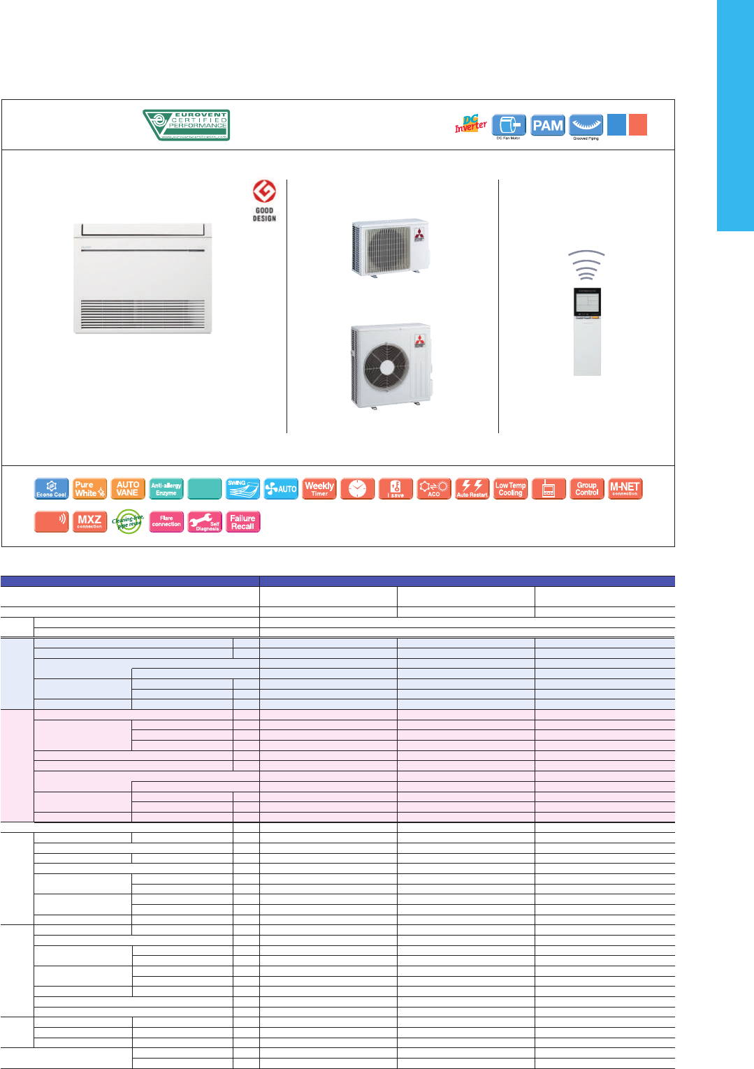
MFZ
SERIES
High Capacity, Energy Savings and a Design in Harmony with Living Spaces
Raise the Value of Your Room to the Next Level.
*The downward airflow is also possible as well as heating.
Cooling Heating
SCOP
4.5
SEER
8.1
SCOP
4.4
MFZ-KJ25VE MFZ-KJ35VE
SEER
6.5
SCOP
4.3
MFZ-KJ50VE
SEER
8.5
SEER Rank A(5.1)
SCOP Rank A(3.8)
Excellent Energy-saving Performance
SEER A
+++
(25) and SCOP A
+
(25/35/50) ratings have been achieved through
development focusing on compliance with European energy-related
product (ErP) regulations.
Weekly Timer
(Introduced in response to market demand)
Temperature settings and On/O control can be managed over a period
of one week using the Weekly Timer. Up to eight setting patterns per cal-
endar day are possible.
Trouble-free Installation and Maintenance
Using the original installation plate that comes as standard equipment,
installation of the unit is a snap. Levelling adjusters are provided, pre-
venting damage to the wall. Generous pipe length (20–30 metres) is
provided, so there is no need to worry about distance to the outdoor
unit. All units are equipped with an automatic self-diagnostics function
as well. Simply access the trouble log recall mode for instant trouble-
shooting.
Operating Current (Max)
Ext.
Piping
Guaranteed Operating Range
[Outdoor]
kW
kWh/a
kW
kW
kW
kW
kW
kW
kW
kW
kWh/a
kW
kW
kW
A
kW
A
mm
kg
m3/min
m3/min
dB(A)
dB(A)
dB(A)
mm
kg
m3/min
m3/min
dB(A)
dB(A)
dB(A)
A
A
mm
m
m
o
C
o
C
MFZ-KJ25VE(2)
MUFZ-KJ25VE
R410A
(*1)
2.5
102
8.5
A
+++
2.5
0.5 - 3.4
0.540
3.4(-10
o
C)
3.4(-10
o
C)
3.4(-10
o
C)
2.4(-15
o
C)
0.0(-10
o
C)
1059
4.5
A
+
3.4
1.2 - 4.6
0.770
9.4
0.016
0.17
600-750-215
15
3.9 - 4.9 - 5.9 - 7.1 - 8.2
3.9 - 5.1 - 6.2 - 7.7 - 9.7
20 - 25 - 30 - 35 - 39
19 - 25 - 30 - 35 - 41
49
550-800-285
37
31.3
33.6
46
51
59
9.2
10
6.35/9.52
20
12
-10 ~ +46
-15 ~ +24
MFZ-KJ35VE(2)
MUFZ-KJ35VE
R410A
(*1)
3.5
150
8.1
A
++
3.5
0.5 - 3.7
0.940
3.5(-10
o
C)
3.5(-10
o
C)
3.5(-10
o
C)
2.9(-15
o
C)
0.0(-10
o
C)
1110
4.4
A
+
4.3
1.2 - 5.5
1.100
9.4
0.016
0.17
600-750-215
15
3.9 - 4.9 - 5.9 - 7.1 - 8.2
3.9 - 5.1 - 6.2 - 7.7 - 9.7
20 - 25 - 30 - 35 - 39
19 - 25 - 30 - 35 - 41
50
550-800-285
37
31.3
33.6
47
51
60
9.2
10
6.35/9.52
20
12
-10 ~ +46
-15 ~ +24
MFZ-KJ50VE(2)
MUFZ-KJ50VE
R410A
(*1)
5.0
266
6.5
A
++
5.0
1.6 - 5.7
1.410
4.4(-10
o
C)
4.4(-10
o
C)
4.4(-10
o
C)
6.0(-15
o
C)
0.0(-10
o
C)
1406
4.3
A
+
6.0
2.2 - 8.2
1.610
14.0
0.038
0.34
600-750-215
15
5.6 - 6.7 - 8.0 - 9.3 - 10.6
6.0 - 7.4 - 9.4 - 11.6 - 14.0
27 - 31 - 35 - 39 - 44
29 - 35 - 40 - 45 - 50
56
880-840-330
55
45.8
45.8
49
51
63
13.6
16
6.35/12.7
30
15
-10 ~ +46
-15 ~ +24
Outdoor power supply
230 / Single / 50
(*1) Refrigerant leakage contributes to climate change. Refrigerant with lower global warming potential (GWP) would contribute less to global warming than a refrigerant with higher GWP, if leaked to the atmosphere. This appliance
contains a refrigerant uid with a GWP equal to 1975. This means that if 1 kg of this refrigerant uid would be leaked to the atmosphere, the impact on global warming would be 1975 times higher than 1 kg of CO
2 , over a period
of 100 years. Never try to interfere with the refrigerant circuit yourself or disassemble the product yourself and always ask a professional.
(*2) Energy consumption based on standard test results. Actual energy consumption will depend on how the appliance is used and where it is located.
(
*3) SHi: Super High
(*4) SEER, SCOP and other related description are based on COMMISSION DELEGATED REGULATION (EU) No.626/2011. The temperature conditions for calculating SCOP are based on “Average Season”.
Input
Operating Current(Max)
Dimensions
Weight
Air Volume
(SLo-Lo-Mid-Hi-SHi
(*3)
)
Sound Level (SPL)
(SLo-Lo-Mid-Hi-SHi
(*3)
)
Sound Level (PWL)
Dimensions
Weight
Air Volume
Sound Level (SPL)
Sound Level (PWL)
Operating Current(Max)
Breaker Size
Diameter
Max.Length
Max.Height
Source
Outdoor(V/Phase/Hz)
SEER
(*4)
Energy eciency class
Energy eciency class
SCOP
(*4)
Design load
Annual electricity consumption
(*2)
Capacity
Total Input
Capacity
Total Input
Design load
Declared Capacity
Back up heating capacity
Annual electricity consumption
(*2)
at reference design temperature
at bivalent temperature
at operation limit temperature
Rated
Min-Max
Rated
Rated
Min-Max
Rated
Rated
H*W*D
Cooling
Heating
Cooling
Heating
Cooling
H*W*D
Cooling
Heating
Cooling
Heating
Cooling
Liquid/Gas
Out-In
Out-In
Cooling
Heating
Inverter Heat PumpType
Indoor Unit
Outdoor Unit
Refrigerant
Power
Supply
Uneven surfaces have been smoothed to provide a simple design with linear beauty, harmonised with all types of interiors.
Three uniquely shaped vanes control the airow and allow the freedom to customize comfort according to preferences.
Images of installed unit
750mm
600mm
145
mm
215
mm
Unique configuration
realising a flat, stylish look
1
4
m
Simple , Flat Design
Multi-ow Vane
Standard
Semi-inbuilt
Simple, symmetrical design
Removable base section
Ingenious structure realizing
low-profile air inlet
Two-block structure to
accommodate various
installation patterns
Air currents can be
controlled freely
Base can be removed to
accentuate the stylish
main body
Warm air is blown
out in a downward
direction and then
sucked back into
the unit to quickly
raise the tempera-
ture of the air being
blown out.
When heating
Rapid heating
When cooling
SCOP
A
+
SEER
A
+++
25
Cooling
Heating
(Average
Season)
Indoor
Unit
Outdoor
Unit
MFZ-KJ25/35/50VE2
Indoor Unit Outdoor Unit
Remote Controller
MFZ-KJ SERIES
MUFZ-KJ25/35VE
MUFZ-KJ50VE
Optional
Optional
Optional
Nano
Platinum
SCOP
A
+
SEER
A
+++
25
Please fill out the requested information
Please fill out the requested information
Optional
Wi-Fi
Interface
MFZ-KJ25/35/50VE2
48
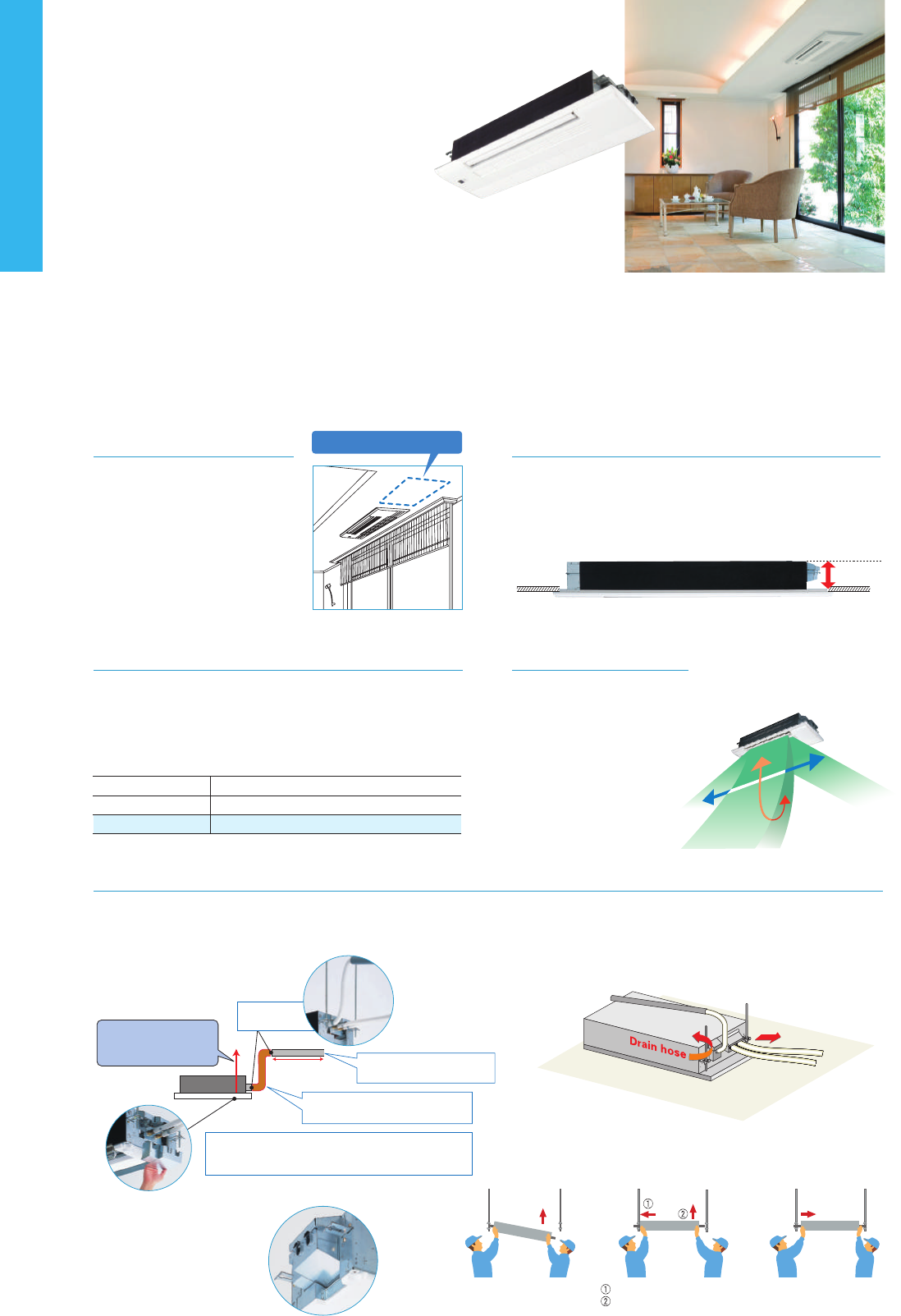
MLZ
SERIES
Introducing a new type of ceiling cassette for the Multi-Split Series with streamed
interior dimensions and a sharp, sleek appearance.
175mm
Ceiling Mounted
Installing the ceiling-mounted MLZ
Series unit in a room creates a more
spacious feel that enhances room
comfort. This overhead format is also
an excellent solution when lighting
equipment is installed at the centre
of the room and fixtures such as
book shelves are mounted on wall
surfaces.
Slim Body
The new units are designed with a slim body (only 175mm high), en-
suring easy installation even when low ceiling cavities limit installa-
tion space. The need for ceiling cavity service space is also elimi-
nated, further reducing the dimensions required for installation.
Easy Installation
A built-in drain pump (500mm lift) and flexible drain joints make attaching the drain hose in the ceiling cavity easy, resulting in simple and fast
installation. Tight yet flexible fittings eliminate the need of wrapping with heat-insulation tape, and ensure that pipe and drain cover connections
are free of condensation.
Insulating material wrapping
only required from this point
Insulation material pretreatment
eliminates need for wrapping.
The newly adopted insulation-free cover eliminates
the need for wrapping pipes with insulation tape and
prevents the forming of condensation.
Flexible drain joints simplify
drain piping work in narrow ceiling areas
●
Drain Piping Supporters
Installation Example
●
Easy Mounting Plate
Suspension work simplified with
well-designed mounting plates
Built-in drain pump
secures drainage
water lift of 500mm
Access door not required
Drain cover
Easy joint
connections!
Secure one side Move unit to the centre
Flexible drain joints
Refrigerant pipe
MLZ-KA25/35/50VA
Set Airflow According to Ceiling Height
Dual-level airflow selection is engineered to accommodate specific
ceiling heights. This is a key feature for adjusting airflow effectively
when it is either too strong or too weak due to being mismatched
with the height of the ceiling.
Up and Down
Left and Right
Standard
High ceiling
25
2.4m
2.7m
2.4m
2.7m
2.4m
2.7m
35 50
Auto Vane Control
Outlet vanes can be moved left
and right, and up and down
using the remote controller. This
improved airflow control feature
solves the problem of drafts.
Push the unit to the other side
Secure the opposite side
MLZ-KA25/35/50VA
For MXZ Connection Only
MLP-440W
OptionalOptional Optional Optional
OptionalOptional
Wi-Fi
Interface
Indoor Unit Outdoor Unit
Panel
Remote Controller
MLZ-KA SERIES
49
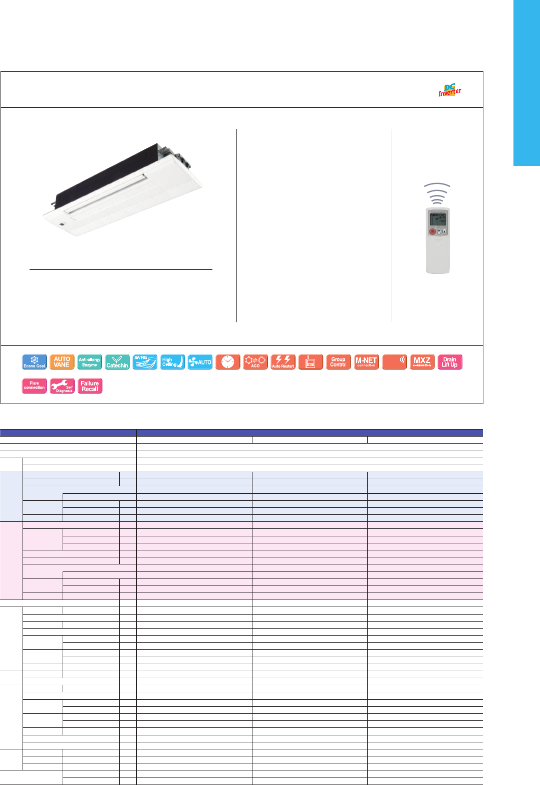
MLZ
SERIES
Introducing a new type of ceiling cassette for the Multi-Split Series with streamed
interior dimensions and a sharp, sleek appearance.
175mm
Ceiling Mounted
Installing the ceiling-mounted MLZ
Series unit in a room creates a more
spacious feel that enhances room
comfort. This overhead format is also
an excellent solution when lighting
equipment is installed at the centre
of the room and fixtures such as
book shelves are mounted on wall
surfaces.
Slim Body
The new units are designed with a slim body (only 175mm high), en-
suring easy installation even when low ceiling cavities limit installa-
tion space. The need for ceiling cavity service space is also elimi-
nated, further reducing the dimensions required for installation.
Easy Installation
A built-in drain pump (500mm lift) and flexible drain joints make attaching the drain hose in the ceiling cavity easy, resulting in simple and fast
installation. Tight yet flexible fittings eliminate the need of wrapping with heat-insulation tape, and ensure that pipe and drain cover connections
are free of condensation.
Insulating material wrapping
only required from this point
Insulation material pretreatment
eliminates need for wrapping.
The newly adopted insulation-free cover eliminates
the need for wrapping pipes with insulation tape and
prevents the forming of condensation.
Flexible drain joints simplify
drain piping work in narrow ceiling areas
●
Drain Piping Supporters
Installation Example
●
Easy Mounting Plate
Suspension work simplified with
well-designed mounting plates
Built-in drain pump
secures drainage
water lift of 500mm
Access door not required
Drain cover
Easy joint
connections!
Secure one side Move unit to the centre
Flexible drain joints
Refrigerant pipe
MLZ-KA25/35/50VA
Set Airflow According to Ceiling Height
Dual-level airflow selection is engineered to accommodate specific
ceiling heights. This is a key feature for adjusting airflow effectively
when it is either too strong or too weak due to being mismatched
with the height of the ceiling.
Up and Down
Left and Right
Standard
High ceiling
25
2.4m
2.7m
2.4m
2.7m
2.4m
2.7m
35 50
Auto Vane Control
Outlet vanes can be moved left
and right, and up and down
using the remote controller. This
improved airflow control feature
solves the problem of drafts.
Push the unit to the other side
Secure the opposite side
MLZ-KA25/35/50VA
For MXZ Connection Only
MLP-440W
OptionalOptional Optional Optional
OptionalOptional
Wi-Fi
Interface
Indoor Unit Outdoor Unit
Panel
Remote Controller
MLZ-KA SERIES
50
Type Inverter Heat Pump
Indoor Unit MLZ-KA25VA MLZ-KA35VA MLZ-KA50VA
Outdoor Unit for MXZ connection
Refrigerant R410A
(*1)
Power
Supply
Source
Outdoor Power supply
Outdoor ( V / Phase / Hz )
230V / Single / 50Hz
Cooling
Design load
kW
- - -
Annual electricity consumption
(*2)
kWh/a
- - -
SEER
(*4)
- - -
Energy efficiency class
- - -
Capacity
Rated
kW
- - -
Min-Max
kW
- - -
Total Input
Rated
kW
- - -
Heating
(Average
Season)
Design load
kW
- - -
Declared
Capacity
at reference design temperature
kW
- - -
at bivalent temperature
kW
- - -
at operation limit temperature
kW
- - -
Back up heating capacity
kW
- - -
Annual electricity consumption
(*2)
kWh/a
- - -
SCOP
(*4)
- - -
Energy efficiency class
- - -
Capacity
Rated
kW
- - -
Min-Max
kW
- - -
Total Input
Rated
kW
- - -
Operating Current (Max)
A
0.4 0.4 0.4
Indoor
Unit
Input
Rated
kW
0.040 0.040 0.040
Operating Current(Max)
A
- - -
Dimensions
H*W*D
mm
175-1102-360 175-1102-360 175-1102-360
Weight
kg
15 15 15
Air Volume (SLo-Lo-
Mid-Hi-SHi
(*3)
(Dry/Wet))
Cooling
m
3
/min
7.2-8.0-8.8 7.3-8.4-9.4 8.3-9.8-11.4
Heating
m
3
/min
7.0-8.2-9.2 7.7-8.8-9.9 8.8-10.3-11.8
Sound Level (SPL)
(SLo-Lo-Mid-Hi-SHi
(*3)
)
Cooling
dB(A)
29-32-35 31-34-37 34-38-43
Heating
dB(A)
28-32-36 31-35-38 34-39-43
Sound Level (PWL)
Cooling
dB(A)
52 54 60
Panel
Dimensions
H*W*D
mm
34-1200-414 34-1200-414 34-1200-414
Weight
kg
3.5 3.5 3.5
Outdoor
Unit
Dimensions
H*W*D
mm
- - -
Weight
kg
- - -
Air Volume
Cooling
m
3
/min
- - -
Heating
m
3
/min
- - -
Sound Level (SPL)
Cooling
dB(A)
- - -
Heating
dB(A)
- - -
Sound Level (PWL)
Cooling
dB(A)
- - -
Operating Current (Max)
A
- - -
Breaker Size
A
- - -
Ext.
Piping
Diameter
Liquid/Gas
mm
6.35/9.52 6.35/9.52 6.35/12.7
Max.Length
Out-In
m
- - -
Max.Height
Out-In
m
- - -
Guaranteed Operating
Range (Outdoor)
Cooling
˚C
- - -
Heating
˚C
- - -
(*1) Refrigerant leakage contributes to climate change. Refrigerant with lower global warming potential (GWP) would contribute less to global warming than a refrigerant with higher GWP, if leaked to the atmosphere. This appliance contains a refrigerant fluid with
a GWP equal to 1975. This means that if 1 kg of this refrigerant fluid would be leaked to the atmosphere, the impact on global warming would be 1975 times higher than 1 kg of CO
2, over a period of 100 years. Never try to interfere with the refrigerant circuit
yourself or disassemble the product yourself and always ask a professional.
(*2) Energy consumption based on standard test results.Actual energy consumption will depend on how the appliance is used and where it is located.
(*3) SHi: Super High
(*4) SEER, SCOP and other related description are based on COMMISSION DELEGATED REGULATION (EU) No.626/2011. The temperature conditions for calculating SCOP are based on “Average Season”.
Type Inverter Heat Pump
Type Inverter Heat Pump
Type Inverter Heat Pump
Type Inverter Heat Pump
Specification on Warmer Condition
Cooling
Design load
kW
Annual electricity consumption
(*2)
kWh/a
SEER
Energy efficiency class
Design load
kW
Declared
Capacity
at reference design temperature
kW
at bivalent temperature
kW
at operation limit temperature
kW
Back up heating capacity
kW
Annual electricity consumption
(*2)
kWh/a
SCOP
Energy efficiency class
Indoor Unit MSZ-HJ25VA MSZ-HJ35VA
Outdoor Unit MUZ-HJ25VA
2.5
171
5.1
A
1.1 (2°C)
1.1 (2°C)
1.1 (2°C)
1.9 (
-
10°C)
0.0 (2°C)
356
4.3
A
+
MUZ-HJ35VA
3.1
212
5.1
A
1.3 (2°C)
1.3 (2°C)
1.3 (2°C)
2.4 (
-
10°C)
0.0 (2°C)
426
4.3
A
+
MSZ-HJ50VA
MUZ-HJ50VA
5.0
292
6.0
A
+
2.1 (2°C)
2.1 (2°C)
2.1 (2°C)
3.8 (
-
10°C)
0.0 (2°C)
539
5.5
A
+++
Refrigerant R410A
(*1)
Cooling
Design load
kW
Annual electricity consumption
(*2)
kWh/a
SEER
Energy efficiency class
Heating
(Warmer
Season)
Design load
kW
Declared
Capacity
at reference design temperature
kW
at bivalent temperature
kW
at operation limit temperature
kW
Back up heating capacity
kW
Annual electricity consumption
(*2)
kWh/a
SCOP
Energy efficiency class
Type Inverter Heat Pump
Indoor Unit MSZ-FH25VE(2) MSZ-FH35VE(2) MSZ-FH50VE(2)
Outdoor Unit MUZ-FH25VE
2.5
96
9.1
A
+++
1.7 (2°C)
1.7 (2°C)
1.7 (2°C)
2.5 (
-
15°C)
0.0 (2°C)
376
6.3
A
+++
MUZ-FH25VEHZ
2.5
96
9.1
A
+++
1.8 (2°C)
1.8 (2°C)
1.8 (2°C)
1.7 (
-
25°C)
0.0 (2°C)
397
6.3
A
+++
MUZ-FH35VE
3.5
138
8.9
A
+++
2.0 (2°C)
2.0 (2°C)
2.0 (2°C)
3.2 (
-
15°C)
0.0 (2°C)
429
6.5
A
+++
MUZ-FH35VEHZ
3.5
138
8.9
A
+++
2.2 (2°C)
2.2 (2°C)
2.2 (2°C)
2.6 (
-
25°C)
0.0 (2°C)
471
4.8 / 6.5
A
+++
MUZ-FH50VE
5.0
244
7.2
A
++
2.5 (2°C)
2.5 (2°C)
2.5 (2°C)
5.2 (
-
15°C)
0.0 (2°C)
614
5.7
A
+++
MUZ-FH50VEHZ
5.0
244
7.2
A
++
3.3 (2°C)
3.3 (2°C)
3.3 (2°C)
3.8 (
-
25°C)
0.0 (2°C)
787
5.9
A
+++
Refrigerant R410A
(*1)
Cooling
Design load
kW
Annual electricity consumption
(*2)
kWh/a
SEER
Energy efficiency class
Design load
kW
Declared
Capacity
at reference design temperature
kW
at bivalent temperature
kW
at operation limit temperature
kW
Back up heating capacity
kW
Annual electricity consumption
(*2)
kWh/a
SCOP
Energy efficiency class
Indoor Unit MSZ-EF25VE2(3) MSZ-EF35VE2(3) MSZ-EF42VE2(3) MSZ-EF50VE2(3)
Outdoor Unit MUZ-EF25VE
2.5
103
8.5
A
+++
1.3 (2°C)
1.3 (2°C)
1.3 (2°C)
2.0 (
-
15°C)
0.0 (2°C)
304
6.0
A
+++
MUZ-EF25VEH
2.5
103
8.5
A
+++
1.3 (2°C)
1.3 (2°C)
1.3 (2°C)
1.6 (
-
20°C)
0.0 (2°C)
304
6.0
A
+++
MUZ-EF35VE
3.5
144
8.5
A
+++
1.6 (2°C)
1.6 (2°C)
1.6 (2°C)
2.4 (
-
15°C)
0.0 (2°C)
396
5.7
A
+++
MUZ-EF35VEH
3.5
144
8.5
A
+++
1.6 (2°C)
1.6 (2°C)
1.6 (2°C)
1.7 (
-
20°C)
0.0 (2°C)
396
5.7
A
+++
MUZ-EF42VE
4.2
192
7.7
A
++
2.1 (2°C)
2.1 (2°C)
2.1 (2°C)
3.4 (
-
15°C)
0.0 (2°C)
491
6.0
A
+++
MUZ-EF50VE
5.0
244
7.2
A
++
2.3 (2°C)
2.3 (2°C)
2.3 (2°C)
3.5 (
-
15°C)
0.0 (2°C)
557
5.8
A
+++
Refrigerant R410A
(*1)
Cooling
Design load
kW
Annual electricity consumption
(*2)
kWh/a
SEER
Energy efficiency class
Design load
kW
Declared
Capacity
at reference design temperature
kW
at bivalent temperature
kW
at operation limit temperature
kW
Back up heating capacity
kW
Annual electricity consumption
(*2)
kWh/a
SCOP
Energy efficiency class
Indoor Unit MSZ-SF25VE2(3) MSZ-SF35VE2(3) MSZ-SF42VE2(3)
Outdoor Unit MUZ-SF25VE
2.5
116
7.6
A
++
1.3 (2°C)
1.3 (2°C)
1.3 (2°C)
2.0 (
-
15°C)
0.0 (2°C)
337
5.4
A
+++
MUZ-SF25VEH
2.5
116
7.6
A
++
1.3 (2°C)
1.3 (2°C)
1.3 (2°C)
1.6 (
-
20°C)
0.0 (2°C)
337
5.4
A
+++
MUZ-SF35VE
3.5
171
7.2
A
++
1.6 (2°C)
1.6 (2°C)
1.6 (2°C)
2.2 (
-
15°C)
0.0 (2°C)
923 / 418
5.4
A
+++
MUZ-SF35VEH
3.5
171
7.2
A
++
1.6 (2°C)
1.6 (2°C)
1.6 (2°C)
1.6 (
-
20°C)
0.0 (2°C)
417
5.4
A
+++
MUZ-SF42VE
4.2
196
7.5
A
++
2.1 (2°C)
2.1 (2°C)
2.1 (2°C)
3.4 (
-
15°C)
0.0 (2°C)
507
5.8
A
+++
MUZ-SF42VEH
4.2
196
7.5
A
++
2.1 (2°C)
2.1 (2°C)
2.1 (2°C)
2.2 (
-
20°C)
0.0 (2°C)
507
5.8
A
+++
MSZ-SF50VE2(3)
MUZ-SF50VE
5.0
246
7.2
A
++
2.3 (2°C)
2.3 (2°C)
2.3 (2°C)
3.4 (
-
15°C)
0.0 (2°C)
563
5.7
A
+++
MUZ-SF50VEH
5.0
246
7.2
A
++
2.3 (2°C)
2.3 (2°C)
2.3 (2°C)
2.3 (
-
20°C)
0.0 (2°C)
563
5.7
A
+++
Refrigerant R410A
(*1)
Cooling
Design load
kW
Annual electricity consumption
(*2)
kWh/a
SEER
Energy efficiency class
Design load
kW
Declared
Capacity
At reference design temperature
kW
at bivalent temperature
kW
at operation limit temperature
kW
Back up heating capacity
kW
Annual electricity consumption
(*2)
kWh/a
SCOP
(*4)
Energy efficiency class
Indoor Unit MSZ-GF60VE(2) MSZ-GF71VE(2)
Outdoor Unit MUZ-GF60VE
6.1
311
6.8
A
++
2.5 (2°C)
2.5 (2°C)
2.5 (2°C)
3.7 (
-
15°C)
0.0 (2°C)
664
5.3
A
+++
MUZ-GF71VE
7.1
364
6.8
A
++
3.7 (2°C)
3.7 (2°C)
3.7 (2°C)
5.4 (
-
15°C)
0.0 (2°C)
963
5.4
A
+++
Refrigerant R410A
(*1)
(*1) Refrigerant leakage contributes to climate change. Refrigerant with lower global warming potential (GWP) would contribute less to global warming than a refrigerant with higher GWP, if leaked to the atmosphere. This appliance contains a refrigerant fluid with
a GWP equal to 1975. This means that if 1 kg of this refrigerant fluid would be leaked to the atmosphere, the impact on global warming would be 1975 times higher than 1 kg of CO2, over a period of 100 years. Never try to interfere with the refrigerant circuit
yourself or disassemble the product yourself and always ask a professional.
(*2) Energy consumption based on standard test results. Actual energy consumption will depend on how the appliance is used and where it is located.
(*1) Refrigerant leakage contributes to climate change. Refrigerant with lower global warming potential (GWP) would contribute less to global warming than a refrigerant with higher GWP, if leaked to the atmosphere. This appliance contains a refrigerant fluid with
a GWP equal to 1975. This means that if 1 kg of this refrigerant fluid would be leaked to the atmosphere, the impact on global warming would be 1975 times higher than 1 kg of CO
2, over a period of 100 years. Never try to interfere with the refrigerant circuit
yourself or disassemble the product yourself and always ask a professional.
(*2) Energy consumption based on standard test results. Actual energy consumption will depend on how the appliance is used and where it is located.
Heating
(Warmer
Season)
Heating
(Warmer
Season)
Heating
(Warmer
Season)
Heating
(Warmer
Season)
Specification on Warmer Condition
Cooling
SEER
Energy efficiency class
dB
dB
Design load
kW
kWh/a
Heating
(Average
season/
Warmer
season)
SCOP
Energy efficiency class
Design load
kW
kW
kW
kW
kW
kWh/a
Back up heating capacity
Declared
Capacity
at reference design temperature
at bivalent temperature
at operation limit temperature
Type Inverter Heat Pump
Indoor MFZ-KJ25VE(2) MFZ-KJ35VE(2) MFZ-KJ50VE(2)
Outdoor
Inside
Outside
MUFZ-KJ25VE
49
59
MUFZ-KJ25VEHZ
49
59
MUFZ-KJ35VE
50
60
MUFZ-KJ35VEHZ
50
60
MUFZ-KJ50VE
56
63
MUFZ-KJ50VEHZ
56
63
Refrigerant
Sound power levels
on cooling mode
Model
R410A GWP 1975
(*1)
8.5
A
+++
102
2.5
4.5/5.1
A
+
/A
+++
1059/511
3.4 (
-
10
°C
)/1.9 (2°C)
3.4 (
-
10°C)/1.9 (2°C)
3.4 (
-
10°C)/1.9 (2°C)
2.4 (
-
15°C)/2.4 (
-
15°C)
0.0 (
-
10°C)/0.0 (2°C)
8.5
A
+++
102
2.5
4.4/5.4
A
+
/A
+++
1104/490
3.5 (
-
10°C)/1.9 (2°C)
3.5 (
-
10°C)/1.9 (2°C)
3.5 (
-
10°C)/1.9 (2°C)
1.6 (
-
25°C)/1.6 (
-
25°C)
0.0 (
-
10°C)/0.0 (2°C)
8.1
A
++
150
3.5
4.4/5.3
A
+
/A
+++
1110/499
3.5 (
-
10°C)/1.9 (2°C)
3.5 (
-
10°C)/1.9 (2°C)
3.5 (
-
10°C)/1.9 (2°C)
2.9 (
-
15°C)/2.9 (
-
15°C)
0.0 (
-
10°C)/0.0 (2°C)
8.1
A
++
150
3.5
4.3/5.4
A
+
/A
+++
1158/510
3.6 (
-
10°C)/2.0 (2°C)
3.6 (
-
10°C)/2.0 (2°C)
3.6 (
-
10°C)/2.0 (2°C)
2.3 (
-
25°C)/2.3 (
-
25°C)
0.0 (
-
10°C)/0.0 (2°C)
6.5
A
++
266
5.0
4.3/5.8
A
+
/A
+++
1406/579
4.4 (
-
10°C)/2.4 (2°C)
4.4 (
-
10°C)/2.4 (2°C)
4.4 (
-
10°C)/2.4 (2°C)
6.0 (
-
15°C)/6.0 (
-
15°C)
0.0 (
-
10°C)/0.0 (2°C)
6.5
A
++
266
5.0
4.2/5.7
A
+
/A
+++
1467/603
4.5 (
-
10°C)/2.5 (2°C)
4.5 (
-
10°C)/2.5 (2°C)
4.5 (
-
10°C)/2.5 (2°C)
3.3 (
-
25°C)/3.3 (
-
25°C)
0.0 (
-
10°C)/0.0 (2°C)
Annual electricity consumption
(*2)
Annual electricity consumption
(*2)
Cooling
SEER
Energy efficiency class
dB
dB
Design load
kW
kWh/a
Heating
(Average
season/
Warmer
season)
SCOP
Energy efficiency class
Design load
kW
kW
kW
kW
kW
kWh/a
Back up heating capacity
Declared
Capacity
at reference design temperature
at bivalent temperature
at operation limit temperature
Type Inverter Heat Pump
Indoor MSZ-FH25VE(2) MSZ-FH35VE(2) MSZ-FH50VE(2)
Outdoor
Inside
Outside
MUZ-FH25VE
58
60
MUZ-FH25VEHZ
58
60
MUZ-FH35VE
58
61
MUZ-FH35VEHZ
58
61
MUZ-FH50VE
60
64
MUZ-FH50VEHZ
60
64
Refrigerant
Sound power levels
on cooling mode
Model
R410A GWP 1975
(*1)
9.1
A
+++
96
2.5
5.1/6.3
A
+++
/A
+++
819/376
3.0 (
-
10°C)/1.7 (2°C)
3.0 (
-
10°C)/1.7 (2°C)
3.0 (
-
10°C)/1.7 (2°C)
2.5 (
-
15°C)/2.5 (
-
15°C)
0.0 (
-
10°C)/0.0 (2°C)
9.1
A
+++
96
2.5
4.9/6.3
A
++
/A
+++
924/397
3.2 (
-
10°C)/1.8 (2°C)
3.2 (
-
10°C)/1.8 (2°C)
3.2 (
-
10°C)/1.8 (2°C)
1.7 (
-
25°C)/1.7 (
-
25°C)
0.0 (
-
10°C)/0.0 (2°C)
8.9
A
+++
138
3.5
5.1/6.5
A
+++
/A
+++
986/429
3.6 (
-
10°C)/2.0 (2°C)
3.6 (
-
10°C)/2.0 (2°C)
3.6 (
-
10°C)/2.0 (2°C)
3.2 (
-
15°C)/3.2 (
-
15°C)
0.0 (
-
10°C)/0.0 (2°C)
8.9
A
+++
138
3.5
4.8/6.5
A
++
/A
+++
1173/471
4.0 (
-
10°C)/2.2 (2°C)
4.0 (
-
10°C)/2.2 (2°C)
4.0 (
-
10°C)/2.2 (2°C)
2.6 (
-
25°C)/2.6 (
-
25°C)
0.0 (
-
10°C)/0.0 (2°C)
7.2
A
++
244
5.0
4.6/5.7
A
++
/A
+++
1372/614
4.5 (
-
10°C)/2.5 (2°C)
4.5 (
-
10°C)/2.5 (2°C)
4.5 (
-
10°C)/2.5 (2°C)
5.2 (
-
15°C)/5.2 (
-
15°C)
0.0 (
-
10°C)/0.0 (2°C)
7.2
A
++
244
5.0
4.2/5.9
A
+
/A
+++
2006/787
6.0 (
-
10°C)/3.3 (2°C)
6.0 (
-
10°C)/3.3 (2°C)
6.0 (
-
10°C)/3.3 (2°C)
3.8 (
-
25°C)/3.8 (
-
25°C)
0.0 (
-
10°C)/0.0 (2°C)
Annual electricity consumption
(*2)
Annual electricity consumption
(*2)
Cooling
SEER
Energy efficiency class
dB
dB
Design load
kW
kWh/a
Heating
(Average
season/
Warmer
season)
SCOP
Energy efficiency class
Design load
kW
kW
kW
kW
kW
kWh/a
Back up heating capacity
Declared
Capacity
at reference design temperature
at bivalent temperature
at operation limit temperature
Type Inverter Heat Pump
Indoor MSZ-EF25VE2(3) MSZ-EF35VE2(3)MSZ-EF42VE2(3) MSZ-EF50VE2(3)
Outdoor
Inside
Outside
MUZ-EF25VE
60
58
MUZ-EF25VEH
60
58
MUZ-EF35VE
60
61
MUZ-EF35VEH
60
61
MUZ-EF42VE
60
62
MUZ-EF50VE
60
65
Refrigerant
Sound power levels
on cooling mode
Model
R410A GWP 1975
(*1)
8.5
A
+++
103
2.5
4.7/6.0
A
++
/A
+++
716/304
2.4 (
-
10°C)/1.3 (2°C)
2.4 (
-
10°C)/1.3 (2°C)
2.4 (
-
10°C)/1.3 (2°C)
2.0 (
-
15°C)/2.0 (
-
15°C)
0.0 (
-
10°C)/0.0 (2°C)
8.5
A
+++
103
2.5
4.6/6.0
A
++
/A
+++
730/304
2.4 (
-
10°C)/1.3 (2°C)
2.4 (
-
10°C)/1.3 (2°C)
2.4 (
-
10°C)/1.3 (2°C)
1.6 (
-
20°C)/1.6 (
-
20°C)
0.0 (
-
10°C)/0.0 (2°C)
8.5
A
+++
144
3.5
4.6/5.7
A
++
/A
+++
882/396
2.9 (
-
10°C)/1.6 (2°C)
2.9 (
-
10°C)/1.6 (2°C)
2.9 (
-
10°C)/1.6 (2°C)
2.4 (
-
15°C)/2.4 (
-
15°C)
0.0 (
-
10°C)/0.0 (2°C)
8.5
A
+++
144
3.5
4.5/5.7
A
+
/A
+++
910/396
2.9 (
-
10°C)/1.6 (2°C)
2.9 (
-
10°C)/1.6 (2°C)
2.9 (
-
10°C)/1.6 (2°C)
1.7 (
-
20°C)/1.7 (
-
20°C)
0.0 (
-
10°C)/0.0 (2°C)
7.7
A
++
192
4.2
4.6/6.0
A
++
/A
+++
1155/491
3.8 (
-
10°C)/2.1 (2°C)
3.8 (
-
10°C)/2.1 (2°C)
3.8 (
-
10°C)/2.1 (2°C)
3.4 (
-
15°C)/3.4 (
-
15°C)
0.0 (
-
10°C)/0.0 (2°C)
7.2
A
++
244
5.0
4.5/5.8
A
+
/A
+++
1309/557
4.2 (
-
10°C)/2.3 (2°C)
4.2 (
-
10°C)/2.3 (2°C)
4.2 (
-
10°C)/2.3 (2°C)
3.5 (
-
15°C)/3.5 (
-
15°C)
0.0 (
-
10°C)/0.0 (2°C)
Annual electricity consumption
(*2)
Annual electricity consumption
(*2)
Cooling
SEER
Energy efficiency class
dB
dB
Design load
kW
kWh/a
Heating
(Average
season/
Warmer
season)
SCOP
Energy efficiency class
Design load
kW
kW
kW
kW
kW
kWh/a
Back up heating capacity
Declared
Capacity
at reference design temperature
at bivalent temperature
at operation limit temperature
Type Inverter Heat Pump
Indoor MSZ-SF25VE2(3)
2(3)
MSZ-SF35VE2(3)MSZ-SF42VE2(3)
Outdoor
Inside
Outside
MUZ-SF25VE
57
58
MUZ-SF25VEH
57
58
MUZ-SF35VE
57
62
MUZ-SF35VEH
57
62
MUZ-SF42VE
57
63
MUZ-SF42VEH
57
63
Refrigerant
Sound power levels
on cooling mode
Model
R410A GWP 1975
(*1)
7.6
A
++
116
2.5
4.4/5.4
A
+
/A
+++
764/337
2.4 (
-
10°C)/1.3 (2°C)
2.4 (
-
10°C)/1.3 (2°C)
2.4 (
-
10°C)/1.3 (2°C)
2.0 (
-
15°C)/2.0 (
-
15°C)
0.0 (
-
10°C)/0.0 (2°C)
7.6
A
++
116
2.5
4.3/5.4
A
+
/A
+++
790/337
2.4 (
-
10°C)/1.3 (2°C)
2.4 (
-
10°C)/1.3 (2°C)
2.4 (
-
10°C)/1.3 (2°C)
1.6 (
-
20°C)/1.6 (
-
20°C)
0.0 (
-
10°C)/0.0 (2°C)
7.2
A
++
171
3.5
4.4/5.4
A
+
/A
+++
923/418
2.9 (
-
10°C)/1.6 (2°C)
2.9 (
-
10°C)/1.6 (2°C)
2.9 (
-
10°C)/1.6 (2°C)
2.2 (
-
15°C)/2.2 (
-
15°C)
0.0 (
-
10°C)/0.0 (2°C)
7.2
A
++
171
3.5
4.3/5.4
A
+
/A
+++
948/417
2.9 (
-
10°C)/1.6 (2°C)
2.9 (
-
10°C)/1.6 (2°C)
2.9 (
-
10°C)/1.6 (2°C)
1.6 (
-
20°C)/1.6 (
-
20°C)
0.0 (
-
10°C)/0.0 (2°C)
MSZ-SF50VE2(3)
MUZ-SF50VE
58
65
MUZ-SF50VEH
58
65
7.2
A
++
246
5.0
4.4/5.7
A
+
/A
+++
1351/563
4.2 (
-
10°C)/2.3 (2°C)
4.2 (
-
10°C)/2.3 (2°C)
4.2 (
-
10°C)/2.3 (2°C)
3.4 (
-
15°C)/3.4 (
-
15°C)
0.0 (
-
10°C)/0.0 (2°C)
7.2
A
++
246
5.0
4.3/5.7
A
+
/A
+++
1380/563
4.2 (
-
10°C)/2.3(2°C)
4.2 (
-
10°C)/2.3 (2°C)
4.2 (
-
10°C)/2.3 (2°C)
2.3 (
-
20°C)/2.3 (
-
20°C)
0.0 (
-
10°C)/0.0 (2°C)
7.5
A
++
196
4.2
4.4/5.8
A
+
/A
+++
1215/507
3.8 (
-
10°C)/2.1 (2°C)
3.8 (
-
10°C)/2.1 (2°C)
3.8 (
-
10°C)/2.1 (2°C)
3.4 (
-
15°C)/3.4 (
-
15°C)
0.0 (
-
10°C)/0.0 (2°C)
7.5
A
++
196
4.2
4.3/5.8
A
+
/A
+++
1242/507
3.8 (
-
10°C)/2.1 (2°C)
3.8 (
-
10°C)/2.1 (2°C)
3.8 (
-
10°C)/2.1 (2°C)
2.2 (
-
20°C)/2.5 (
-
20°C)
0.0 (
-
10°C)/0.0 (2°C)
Annual electricity consumption
(*2)
Annual electricity consumption
(*2)
Cooling
SEER
Energy efficiency class
dB
dB
Design load
kW
kWh/a
Heating
(Average
season/
Warmer
season)
SCOP
Energy efficiency class
Design load
kW
kW
kW
kW
kW
kWh/a
Back up heating capacity
Declared
Capacity
at reference design temperature
at bivalent temperature
at operation limit temperature
Type Inverter Heat Pump
Indoor MSZ-GF60VE(2)
MUZ-GF60VE
65
65
Outdoor
Inside
Outside
Refrigerant
Sound power levels
on cooling mode
Model
R410A GWP 1975
(*1)
6.8
A
++
311
6.1
4.3/5.3
A
+
/A
+++
1489/664
4.6 (
-
10°C)/2.5 (2°C)
4.6 (
-
10°C)/2.5 (2°C)
4.6 (
-
10°C)/2.5 (2°C)
3.7 (
-
15°C)/3.7 (
-
15°C)
0.0 (
-
10°C)/0.0 (2°C)
6.8
A
++
364
7.1
4.2/5.4
A
+
/A
+++
2204/963
6.7 (
-
10°C)/3.7 (2°C)
6.7 (
-
10°C)/3.7 (2°C)
6.7 (
-
10°C)/3.7 (2°C)
5.4 (
-
15°C)/5.4 (
-
15°C)
0.0 (
-
10°C)/0.0 (2°C)
MSZ-GF71VE(2)
MUZ-GF71VE
65
65
Annual electricity consumption
(*2)
Annual electricity consumption
(*2)
MSZ-HJ25VA
MUZ-HJ25VA
57
63
MSZ-HJ35VA
MUZ-HJ35VA
60
64
R410A GWP 1975
(*1)
5.1
A
171
2.5
3.8/4.3
A/A
+
698/356
1.9 (
-
10°C)/1.1 (2°C)
1.9 (
-
10°C)/1.1 (2°C)
1.9 (
-
10°C)/1.1 (2°C)
1.9 (
-
10°C)/1.9 (
-
10°C)
0.0 (
-
10°C)/0.0 (2°C)
5.1
A
212
3.1
3.8/4.3
A/A
+
885/426
2.4 (
-
10°C)/1.3 (2°C)
2.4 (
-
10°C)/1.3 (2°C)
2.4 (
-
10°C)/1.3 (2°C)
2.4 (
-
10°C)/2.4 (
-
10°C)
0.0 (
-
10°C)/0.0 (2°C)
MSZ-HJ50VA
MUZ-HJ50VA
60
64
6.0
A
+
292
5.0
4.2/5.5
A
+
/A
+++
1267/539
3.8 (
-
10°C)/2.1 (2°C)
3.8 (
-
10°C)/2.1 (2°C)
3.8 (
-
10°C)/2.1 (2°C)
3.8 (
-
10°C)/3.8 (
-
10°C)
0.0 (
-
10°C)/0.0 (2°C)
MSZ-HJ60VA
MUZ-HJ60VA
65
65
6.0
A
+
354
6.1
4.1/5.1
A
+
/A
+++
1544/674
4.6 (
-
10°C)/2.5 (2°C)
4.6 (
-
10°C)/2.5 (2°C)
4.6 (
-
10°C)/2.5 (2°C)
4.6 (
-
10°C)/4.6 (
-
10°C)
0.0 (
-
10°C)/0.0 (2°C)
MSZ-HJ71VA
MUZ-HJ71VA
65
66
5.6
A
+
441
7.1
4.0/4.9
A
+
/A
++
1854/813
5.4 (
-
10°C)/2.9 (2°C)
5.4 (
-
10°C)/2.9 (2°C)
5.4 (
-
10°C)/2.9 (2°C)
5.4 (
-
10°C)/5.4 (
-
10°C)
0.0 (
-
10°C)/0.0 (2°C)
51
Type Inverter Heat Pump
Type Inverter Heat Pump
Type Inverter Heat Pump
Type Inverter Heat Pump
Specification on Warmer Condition
Cooling
Design load
kW
Annual electricity consumption
(*2)
kWh/a
SEER
Energy efficiency class
Design load
kW
Declared
Capacity
at reference design temperature
kW
at bivalent temperature
kW
at operation limit temperature
kW
Back up heating capacity
kW
Annual electricity consumption
(*2)
kWh/a
SCOP
Energy efficiency class
Indoor Unit MSZ-HJ25VA MSZ-HJ35VA
Outdoor Unit MUZ-HJ25VA
2.5
171
5.1
A
1.1 (2°C)
1.1 (2°C)
1.1 (2°C)
1.9 (
-
10°C)
0.0 (2°C)
356
4.3
A
+
MUZ-HJ35VA
3.1
212
5.1
A
1.3 (2°C)
1.3 (2°C)
1.3 (2°C)
2.4 (
-
10°C)
0.0 (2°C)
426
4.3
A
+
MSZ-HJ50VA
MUZ-HJ50VA
5.0
292
6.0
A
+
2.1 (2°C)
2.1 (2°C)
2.1 (2°C)
3.8 (
-
10°C)
0.0 (2°C)
539
5.5
A
+++
Refrigerant R410A
(*1)
Cooling
Design load
kW
Annual electricity consumption
(*2)
kWh/a
SEER
Energy efficiency class
Heating
(Warmer
Season)
Design load
kW
Declared
Capacity
at reference design temperature
kW
at bivalent temperature
kW
at operation limit temperature
kW
Back up heating capacity
kW
Annual electricity consumption
(*2)
kWh/a
SCOP
Energy efficiency class
Type Inverter Heat Pump
Indoor Unit MSZ-FH25VE(2) MSZ-FH35VE(2) MSZ-FH50VE(2)
Outdoor Unit MUZ-FH25VE
2.5
96
9.1
A
+++
1.7 (2°C)
1.7 (2°C)
1.7 (2°C)
2.5 (
-
15°C)
0.0 (2°C)
376
6.3
A
+++
MUZ-FH25VEHZ
2.5
96
9.1
A
+++
1.8 (2°C)
1.8 (2°C)
1.8 (2°C)
1.7 (
-
25°C)
0.0 (2°C)
397
6.3
A
+++
MUZ-FH35VE
3.5
138
8.9
A
+++
2.0 (2°C)
2.0 (2°C)
2.0 (2°C)
3.2 (
-
15°C)
0.0 (2°C)
429
6.5
A
+++
MUZ-FH35VEHZ
3.5
138
8.9
A
+++
2.2 (2°C)
2.2 (2°C)
2.2 (2°C)
2.6 (
-
25°C)
0.0 (2°C)
471
4.8 / 6.5
A
+++
MUZ-FH50VE
5.0
244
7.2
A
++
2.5 (2°C)
2.5 (2°C)
2.5 (2°C)
5.2 (
-
15°C)
0.0 (2°C)
614
5.7
A
+++
MUZ-FH50VEHZ
5.0
244
7.2
A
++
3.3 (2°C)
3.3 (2°C)
3.3 (2°C)
3.8 (
-
25°C)
0.0 (2°C)
787
5.9
A
+++
Refrigerant R410A
(*1)
Cooling
Design load
kW
Annual electricity consumption
(*2)
kWh/a
SEER
Energy efficiency class
Design load
kW
Declared
Capacity
at reference design temperature
kW
at bivalent temperature
kW
at operation limit temperature
kW
Back up heating capacity
kW
Annual electricity consumption
(*2)
kWh/a
SCOP
Energy efficiency class
Indoor Unit MSZ-EF25VE2(3) MSZ-EF35VE2(3) MSZ-EF42VE2(3) MSZ-EF50VE2(3)
Outdoor Unit MUZ-EF25VE
2.5
103
8.5
A
+++
1.3 (2°C)
1.3 (2°C)
1.3 (2°C)
2.0 (
-
15°C)
0.0 (2°C)
304
6.0
A
+++
MUZ-EF25VEH
2.5
103
8.5
A
+++
1.3 (2°C)
1.3 (2°C)
1.3 (2°C)
1.6 (
-
20°C)
0.0 (2°C)
304
6.0
A
+++
MUZ-EF35VE
3.5
144
8.5
A
+++
1.6 (2°C)
1.6 (2°C)
1.6 (2°C)
2.4 (
-
15°C)
0.0 (2°C)
396
5.7
A
+++
MUZ-EF35VEH
3.5
144
8.5
A
+++
1.6 (2°C)
1.6 (2°C)
1.6 (2°C)
1.7 (
-
20°C)
0.0 (2°C)
396
5.7
A
+++
MUZ-EF42VE
4.2
192
7.7
A
++
2.1 (2°C)
2.1 (2°C)
2.1 (2°C)
3.4 (
-
15°C)
0.0 (2°C)
491
6.0
A
+++
MUZ-EF50VE
5.0
244
7.2
A
++
2.3 (2°C)
2.3 (2°C)
2.3 (2°C)
3.5 (
-
15°C)
0.0 (2°C)
557
5.8
A
+++
Refrigerant R410A
(*1)
Cooling
Design load
kW
Annual electricity consumption
(*2)
kWh/a
SEER
Energy efficiency class
Design load
kW
Declared
Capacity
at reference design temperature
kW
at bivalent temperature
kW
at operation limit temperature
kW
Back up heating capacity
kW
Annual electricity consumption
(*2)
kWh/a
SCOP
Energy efficiency class
Indoor Unit MSZ-SF25VE2(3) MSZ-SF35VE2(3) MSZ-SF42VE2(3)
Outdoor Unit MUZ-SF25VE
2.5
116
7.6
A
++
1.3 (2°C)
1.3 (2°C)
1.3 (2°C)
2.0 (
-
15°C)
0.0 (2°C)
337
5.4
A
+++
MUZ-SF25VEH
2.5
116
7.6
A
++
1.3 (2°C)
1.3 (2°C)
1.3 (2°C)
1.6 (
-
20°C)
0.0 (2°C)
337
5.4
A
+++
MUZ-SF35VE
3.5
171
7.2
A
++
1.6 (2°C)
1.6 (2°C)
1.6 (2°C)
2.2 (
-
15°C)
0.0 (2°C)
923 / 418
5.4
A
+++
MUZ-SF35VEH
3.5
171
7.2
A
++
1.6 (2°C)
1.6 (2°C)
1.6 (2°C)
1.6 (
-
20°C)
0.0 (2°C)
417
5.4
A
+++
MUZ-SF42VE
4.2
196
7.5
A
++
2.1 (2°C)
2.1 (2°C)
2.1 (2°C)
3.4 (
-
15°C)
0.0 (2°C)
507
5.8
A
+++
MUZ-SF42VEH
4.2
196
7.5
A
++
2.1 (2°C)
2.1 (2°C)
2.1 (2°C)
2.2 (
-
20°C)
0.0 (2°C)
507
5.8
A
+++
MSZ-SF50VE2(3)
MUZ-SF50VE
5.0
246
7.2
A
++
2.3 (2°C)
2.3 (2°C)
2.3 (2°C)
3.4 (
-
15°C)
0.0 (2°C)
563
5.7
A
+++
MUZ-SF50VEH
5.0
246
7.2
A
++
2.3 (2°C)
2.3 (2°C)
2.3 (2°C)
2.3 (
-
20°C)
0.0 (2°C)
563
5.7
A
+++
Refrigerant R410A
(*1)
Cooling
Design load
kW
Annual electricity consumption
(*2)
kWh/a
SEER
Energy efficiency class
Design load
kW
Declared
Capacity
At reference design temperature
kW
at bivalent temperature
kW
at operation limit temperature
kW
Back up heating capacity
kW
Annual electricity consumption
(*2)
kWh/a
SCOP
(*4)
Energy efficiency class
Indoor Unit MSZ-GF60VE(2) MSZ-GF71VE(2)
Outdoor Unit MUZ-GF60VE
6.1
311
6.8
A
++
2.5 (2°C)
2.5 (2°C)
2.5 (2°C)
3.7 (
-
15°C)
0.0 (2°C)
664
5.3
A
+++
MUZ-GF71VE
7.1
364
6.8
A
++
3.7 (2°C)
3.7 (2°C)
3.7 (2°C)
5.4 (
-
15°C)
0.0 (2°C)
963
5.4
A
+++
Refrigerant R410A
(*1)
(*1) Refrigerant leakage contributes to climate change. Refrigerant with lower global warming potential (GWP) would contribute less to global warming than a refrigerant with higher GWP, if leaked to the atmosphere. This appliance contains a refrigerant fluid with
a GWP equal to 1975. This means that if 1 kg of this refrigerant fluid would be leaked to the atmosphere, the impact on global warming would be 1975 times higher than 1 kg of CO2, over a period of 100 years. Never try to interfere with the refrigerant circuit
yourself or disassemble the product yourself and always ask a professional.
(*2) Energy consumption based on standard test results. Actual energy consumption will depend on how the appliance is used and where it is located.
(*1) Refrigerant leakage contributes to climate change. Refrigerant with lower global warming potential (GWP) would contribute less to global warming than a refrigerant with higher GWP, if leaked to the atmosphere. This appliance contains a refrigerant fluid with
a GWP equal to 1975. This means that if 1 kg of this refrigerant fluid would be leaked to the atmosphere, the impact on global warming would be 1975 times higher than 1 kg of CO
2, over a period of 100 years. Never try to interfere with the refrigerant circuit
yourself or disassemble the product yourself and always ask a professional.
(*2) Energy consumption based on standard test results. Actual energy consumption will depend on how the appliance is used and where it is located.
Heating
(Warmer
Season)
Heating
(Warmer
Season)
Heating
(Warmer
Season)
Heating
(Warmer
Season)
Specification on Warmer Condition
Cooling
SEER
Energy efficiency class
dB
dB
Design load
kW
kWh/a
Heating
(Average
season/
Warmer
season)
SCOP
Energy efficiency class
Design load
kW
kW
kW
kW
kW
kWh/a
Back up heating capacity
Declared
Capacity
at reference design temperature
at bivalent temperature
at operation limit temperature
Type Inverter Heat Pump
Indoor MFZ-KJ25VE(2) MFZ-KJ35VE(2) MFZ-KJ50VE(2)
Outdoor
Inside
Outside
MUFZ-KJ25VE
49
59
MUFZ-KJ25VEHZ
49
59
MUFZ-KJ35VE
50
60
MUFZ-KJ35VEHZ
50
60
MUFZ-KJ50VE
56
63
MUFZ-KJ50VEHZ
56
63
Refrigerant
Sound power levels
on cooling mode
Model
R410A GWP 1975
(*1)
8.5
A
+++
102
2.5
4.5/5.1
A
+
/A
+++
1059/511
3.4 (
-
10
°C
)/1.9 (2°C)
3.4 (
-
10°C)/1.9 (2°C)
3.4 (
-
10°C)/1.9 (2°C)
2.4 (
-
15°C)/2.4 (
-
15°C)
0.0 (
-
10°C)/0.0 (2°C)
8.5
A
+++
102
2.5
4.4/5.4
A
+
/A
+++
1104/490
3.5 (
-
10°C)/1.9 (2°C)
3.5 (
-
10°C)/1.9 (2°C)
3.5 (
-
10°C)/1.9 (2°C)
1.6 (
-
25°C)/1.6 (
-
25°C)
0.0 (
-
10°C)/0.0 (2°C)
8.1
A
++
150
3.5
4.4/5.3
A
+
/A
+++
1110/499
3.5 (
-
10°C)/1.9 (2°C)
3.5 (
-
10°C)/1.9 (2°C)
3.5 (
-
10°C)/1.9 (2°C)
2.9 (
-
15°C)/2.9 (
-
15°C)
0.0 (
-
10°C)/0.0 (2°C)
8.1
A
++
150
3.5
4.3/5.4
A
+
/A
+++
1158/510
3.6 (
-
10°C)/2.0 (2°C)
3.6 (
-
10°C)/2.0 (2°C)
3.6 (
-
10°C)/2.0 (2°C)
2.3 (
-
25°C)/2.3 (
-
25°C)
0.0 (
-
10°C)/0.0 (2°C)
6.5
A
++
266
5.0
4.3/5.8
A
+
/A
+++
1406/579
4.4 (
-
10°C)/2.4 (2°C)
4.4 (
-
10°C)/2.4 (2°C)
4.4 (
-
10°C)/2.4 (2°C)
6.0 (
-
15°C)/6.0 (
-
15°C)
0.0 (
-
10°C)/0.0 (2°C)
6.5
A
++
266
5.0
4.2/5.7
A
+
/A
+++
1467/603
4.5 (
-
10°C)/2.5 (2°C)
4.5 (
-
10°C)/2.5 (2°C)
4.5 (
-
10°C)/2.5 (2°C)
3.3 (
-
25°C)/3.3 (
-
25°C)
0.0 (
-
10°C)/0.0 (2°C)
Annual electricity consumption
(*2)
Annual electricity consumption
(*2)
Cooling
SEER
Energy efficiency class
dB
dB
Design load
kW
kWh/a
Heating
(Average
season/
Warmer
season)
SCOP
Energy efficiency class
Design load
kW
kW
kW
kW
kW
kWh/a
Back up heating capacity
Declared
Capacity
at reference design temperature
at bivalent temperature
at operation limit temperature
Type Inverter Heat Pump
Indoor MSZ-FH25VE(2) MSZ-FH35VE(2) MSZ-FH50VE(2)
Outdoor
Inside
Outside
MUZ-FH25VE
58
60
MUZ-FH25VEHZ
58
60
MUZ-FH35VE
58
61
MUZ-FH35VEHZ
58
61
MUZ-FH50VE
60
64
MUZ-FH50VEHZ
60
64
Refrigerant
Sound power levels
on cooling mode
Model
R410A GWP 1975
(*1)
9.1
A
+++
96
2.5
5.1/6.3
A
+++
/A
+++
819/376
3.0 (
-
10°C)/1.7 (2°C)
3.0 (
-
10°C)/1.7 (2°C)
3.0 (
-
10°C)/1.7 (2°C)
2.5 (
-
15°C)/2.5 (
-
15°C)
0.0 (
-
10°C)/0.0 (2°C)
9.1
A
+++
96
2.5
4.9/6.3
A
++
/A
+++
924/397
3.2 (
-
10°C)/1.8 (2°C)
3.2 (
-
10°C)/1.8 (2°C)
3.2 (
-
10°C)/1.8 (2°C)
1.7 (
-
25°C)/1.7 (
-
25°C)
0.0 (
-
10°C)/0.0 (2°C)
8.9
A
+++
138
3.5
5.1/6.5
A
+++
/A
+++
986/429
3.6 (
-
10°C)/2.0 (2°C)
3.6 (
-
10°C)/2.0 (2°C)
3.6 (
-
10°C)/2.0 (2°C)
3.2 (
-
15°C)/3.2 (
-
15°C)
0.0 (
-
10°C)/0.0 (2°C)
8.9
A
+++
138
3.5
4.8/6.5
A
++
/A
+++
1173/471
4.0 (
-
10°C)/2.2 (2°C)
4.0 (
-
10°C)/2.2 (2°C)
4.0 (
-
10°C)/2.2 (2°C)
2.6 (
-
25°C)/2.6 (
-
25°C)
0.0 (
-
10°C)/0.0 (2°C)
7.2
A
++
244
5.0
4.6/5.7
A
++
/A
+++
1372/614
4.5 (
-
10°C)/2.5 (2°C)
4.5 (
-
10°C)/2.5 (2°C)
4.5 (
-
10°C)/2.5 (2°C)
5.2 (
-
15°C)/5.2 (
-
15°C)
0.0 (
-
10°C)/0.0 (2°C)
7.2
A
++
244
5.0
4.2/5.9
A
+
/A
+++
2006/787
6.0 (
-
10°C)/3.3 (2°C)
6.0 (
-
10°C)/3.3 (2°C)
6.0 (
-
10°C)/3.3 (2°C)
3.8 (
-
25°C)/3.8 (
-
25°C)
0.0 (
-
10°C)/0.0 (2°C)
Annual electricity consumption
(*2)
Annual electricity consumption
(*2)
Cooling
SEER
Energy efficiency class
dB
dB
Design load
kW
kWh/a
Heating
(Average
season/
Warmer
season)
SCOP
Energy efficiency class
Design load
kW
kW
kW
kW
kW
kWh/a
Back up heating capacity
Declared
Capacity
at reference design temperature
at bivalent temperature
at operation limit temperature
Type Inverter Heat Pump
Indoor MSZ-EF25VE2(3) MSZ-EF35VE2(3)MSZ-EF42VE2(3) MSZ-EF50VE2(3)
Outdoor
Inside
Outside
MUZ-EF25VE
60
58
MUZ-EF25VEH
60
58
MUZ-EF35VE
60
61
MUZ-EF35VEH
60
61
MUZ-EF42VE
60
62
MUZ-EF50VE
60
65
Refrigerant
Sound power levels
on cooling mode
Model
R410A GWP 1975
(*1)
8.5
A
+++
103
2.5
4.7/6.0
A
++
/A
+++
716/304
2.4 (
-
10°C)/1.3 (2°C)
2.4 (
-
10°C)/1.3 (2°C)
2.4 (
-
10°C)/1.3 (2°C)
2.0 (
-
15°C)/2.0 (
-
15°C)
0.0 (
-
10°C)/0.0 (2°C)
8.5
A
+++
103
2.5
4.6/6.0
A
++
/A
+++
730/304
2.4 (
-
10°C)/1.3 (2°C)
2.4 (
-
10°C)/1.3 (2°C)
2.4 (
-
10°C)/1.3 (2°C)
1.6 (
-
20°C)/1.6 (
-
20°C)
0.0 (
-
10°C)/0.0 (2°C)
8.5
A
+++
144
3.5
4.6/5.7
A
++
/A
+++
882/396
2.9 (
-
10°C)/1.6 (2°C)
2.9 (
-
10°C)/1.6 (2°C)
2.9 (
-
10°C)/1.6 (2°C)
2.4 (
-
15°C)/2.4 (
-
15°C)
0.0 (
-
10°C)/0.0 (2°C)
8.5
A
+++
144
3.5
4.5/5.7
A
+
/A
+++
910/396
2.9 (
-
10°C)/1.6 (2°C)
2.9 (
-
10°C)/1.6 (2°C)
2.9 (
-
10°C)/1.6 (2°C)
1.7 (
-
20°C)/1.7 (
-
20°C)
0.0 (
-
10°C)/0.0 (2°C)
7.7
A
++
192
4.2
4.6/6.0
A
++
/A
+++
1155/491
3.8 (
-
10°C)/2.1 (2°C)
3.8 (
-
10°C)/2.1 (2°C)
3.8 (
-
10°C)/2.1 (2°C)
3.4 (
-
15°C)/3.4 (
-
15°C)
0.0 (
-
10°C)/0.0 (2°C)
7.2
A
++
244
5.0
4.5/5.8
A
+
/A
+++
1309/557
4.2 (
-
10°C)/2.3 (2°C)
4.2 (
-
10°C)/2.3 (2°C)
4.2 (
-
10°C)/2.3 (2°C)
3.5 (
-
15°C)/3.5 (
-
15°C)
0.0 (
-
10°C)/0.0 (2°C)
Annual electricity consumption
(*2)
Annual electricity consumption
(*2)
Cooling
SEER
Energy efficiency class
dB
dB
Design load
kW
kWh/a
Heating
(Average
season/
Warmer
season)
SCOP
Energy efficiency class
Design load
kW
kW
kW
kW
kW
kWh/a
Back up heating capacity
Declared
Capacity
at reference design temperature
at bivalent temperature
at operation limit temperature
Type Inverter Heat Pump
Indoor MSZ-SF25VE2(3)
2(3)
MSZ-SF35VE2(3)MSZ-SF42VE2(3)
Outdoor
Inside
Outside
MUZ-SF25VE
57
58
MUZ-SF25VEH
57
58
MUZ-SF35VE
57
62
MUZ-SF35VEH
57
62
MUZ-SF42VE
57
63
MUZ-SF42VEH
57
63
Refrigerant
Sound power levels
on cooling mode
Model
R410A GWP 1975
(*1)
7.6
A
++
116
2.5
4.4/5.4
A
+
/A
+++
764/337
2.4 (
-
10°C)/1.3 (2°C)
2.4 (
-
10°C)/1.3 (2°C)
2.4 (
-
10°C)/1.3 (2°C)
2.0 (
-
15°C)/2.0 (
-
15°C)
0.0 (
-
10°C)/0.0 (2°C)
7.6
A
++
116
2.5
4.3/5.4
A
+
/A
+++
790/337
2.4 (
-
10°C)/1.3 (2°C)
2.4 (
-
10°C)/1.3 (2°C)
2.4 (
-
10°C)/1.3 (2°C)
1.6 (
-
20°C)/1.6 (
-
20°C)
0.0 (
-
10°C)/0.0 (2°C)
7.2
A
++
171
3.5
4.4/5.4
A
+
/A
+++
923/418
2.9 (
-
10°C)/1.6 (2°C)
2.9 (
-
10°C)/1.6 (2°C)
2.9 (
-
10°C)/1.6 (2°C)
2.2 (
-
15°C)/2.2 (
-
15°C)
0.0 (
-
10°C)/0.0 (2°C)
7.2
A
++
171
3.5
4.3/5.4
A
+
/A
+++
948/417
2.9 (
-
10°C)/1.6 (2°C)
2.9 (
-
10°C)/1.6 (2°C)
2.9 (
-
10°C)/1.6 (2°C)
1.6 (
-
20°C)/1.6 (
-
20°C)
0.0 (
-
10°C)/0.0 (2°C)
MSZ-SF50VE2(3)
MUZ-SF50VE
58
65
MUZ-SF50VEH
58
65
7.2
A
++
246
5.0
4.4/5.7
A
+
/A
+++
1351/563
4.2 (
-
10°C)/2.3 (2°C)
4.2 (
-
10°C)/2.3 (2°C)
4.2 (
-
10°C)/2.3 (2°C)
3.4 (
-
15°C)/3.4 (
-
15°C)
0.0 (
-
10°C)/0.0 (2°C)
7.2
A
++
246
5.0
4.3/5.7
A
+
/A
+++
1380/563
4.2 (
-
10°C)/2.3(2°C)
4.2 (
-
10°C)/2.3 (2°C)
4.2 (
-
10°C)/2.3 (2°C)
2.3 (
-
20°C)/2.3 (
-
20°C)
0.0 (
-
10°C)/0.0 (2°C)
7.5
A
++
196
4.2
4.4/5.8
A
+
/A
+++
1215/507
3.8 (
-
10°C)/2.1 (2°C)
3.8 (
-
10°C)/2.1 (2°C)
3.8 (
-
10°C)/2.1 (2°C)
3.4 (
-
15°C)/3.4 (
-
15°C)
0.0 (
-
10°C)/0.0 (2°C)
7.5
A
++
196
4.2
4.3/5.8
A
+
/A
+++
1242/507
3.8 (
-
10°C)/2.1 (2°C)
3.8 (
-
10°C)/2.1 (2°C)
3.8 (
-
10°C)/2.1 (2°C)
2.2 (
-
20°C)/2.5 (
-
20°C)
0.0 (
-
10°C)/0.0 (2°C)
Annual electricity consumption
(*2)
Annual electricity consumption
(*2)
Cooling
SEER
Energy efficiency class
dB
dB
Design load
kW
kWh/a
Heating
(Average
season/
Warmer
season)
SCOP
Energy efficiency class
Design load
kW
kW
kW
kW
kW
kWh/a
Back up heating capacity
Declared
Capacity
at reference design temperature
at bivalent temperature
at operation limit temperature
Type Inverter Heat Pump
Indoor MSZ-GF60VE(2)
MUZ-GF60VE
65
65
Outdoor
Inside
Outside
Refrigerant
Sound power levels
on cooling mode
Model
R410A GWP 1975
(*1)
6.8
A
++
311
6.1
4.3/5.3
A
+
/A
+++
1489/664
4.6 (
-
10°C)/2.5 (2°C)
4.6 (
-
10°C)/2.5 (2°C)
4.6 (
-
10°C)/2.5 (2°C)
3.7 (
-
15°C)/3.7 (
-
15°C)
0.0 (
-
10°C)/0.0 (2°C)
6.8
A
++
364
7.1
4.2/5.4
A
+
/A
+++
2204/963
6.7 (
-
10°C)/3.7 (2°C)
6.7 (
-
10°C)/3.7 (2°C)
6.7 (
-
10°C)/3.7 (2°C)
5.4 (
-
15°C)/5.4 (
-
15°C)
0.0 (
-
10°C)/0.0 (2°C)
MSZ-GF71VE(2)
MUZ-GF71VE
65
65
Annual electricity consumption
(*2)
Annual electricity consumption
(*2)
MSZ-HJ25VA
MUZ-HJ25VA
57
63
MSZ-HJ35VA
MUZ-HJ35VA
60
64
R410A GWP 1975
(*1)
5.1
A
171
2.5
3.8/4.3
A/A
+
698/356
1.9 (
-
10°C)/1.1 (2°C)
1.9 (
-
10°C)/1.1 (2°C)
1.9 (
-
10°C)/1.1 (2°C)
1.9 (
-
10°C)/1.9 (
-
10°C)
0.0 (
-
10°C)/0.0 (2°C)
5.1
A
212
3.1
3.8/4.3
A/A
+
885/426
2.4 (
-
10°C)/1.3 (2°C)
2.4 (
-
10°C)/1.3 (2°C)
2.4 (
-
10°C)/1.3 (2°C)
2.4 (
-
10°C)/2.4 (
-
10°C)
0.0 (
-
10°C)/0.0 (2°C)
MSZ-HJ50VA
MUZ-HJ50VA
60
64
6.0
A
+
292
5.0
4.2/5.5
A
+
/A
+++
1267/539
3.8 (
-
10°C)/2.1 (2°C)
3.8 (
-
10°C)/2.1 (2°C)
3.8 (
-
10°C)/2.1 (2°C)
3.8 (
-
10°C)/3.8 (
-
10°C)
0.0 (
-
10°C)/0.0 (2°C)
MSZ-HJ60VA
MUZ-HJ60VA
65
65
6.0
A
+
354
6.1
4.1/5.1
A
+
/A
+++
1544/674
4.6 (
-
10°C)/2.5 (2°C)
4.6 (
-
10°C)/2.5 (2°C)
4.6 (
-
10°C)/2.5 (2°C)
4.6 (
-
10°C)/4.6 (
-
10°C)
0.0 (
-
10°C)/0.0 (2°C)
MSZ-HJ71VA
MUZ-HJ71VA
65
66
5.6
A
+
441
7.1
4.0/4.9
A
+
/A
++
1854/813
5.4 (
-
10°C)/2.9 (2°C)
5.4 (
-
10°C)/2.9 (2°C)
5.4 (
-
10°C)/2.9 (2°C)
5.4 (
-
10°C)/5.4 (
-
10°C)
0.0 (
-
10°C)/0.0 (2°C)
52

53
SERIES
SELECT INDOOR UNIT
SELECTION
Series line-up consists of two types of indoor units.
Choose the model that best matches room conditions.
Select the optimal unit and capacity required to match room construction and air conditioning requirements.
SELECT OUTDOOR UNIT
There is one outdoor unit for respective indoor units.
✽
To conrm compatibility with the MXZ Series multi-type system, refer to the MXZ Series page.
Units without Remote Controller
SEZ-KD25VAQ
SEZ-KD35VAQ
SEZ-KD50VAQ
SEZ-KD60VAQ
SEZ-KD71VAQ
*
Requires PAR-32MAA or PAC-YT52CRA remote controller.
Units with Wireless Remote Controller
SEZ-KD25VAL
SEZ-KD35VAL
SEZ-KD50VAL
SEZ-KD60VAL
SEZ-KD71VAL
SUZ-KA25/35VA5 SUZ-KA50/60/71VA5
STEP 1
STEP 2
Units without Remote Controller
SLZ-KF25VA2
SLZ-KF35VA2
SLZ-KF50VA2
SLZ-KF60VA2
*
Requires PAR-32MAA or PAC-YT52CRA
or PAR-SL97A-E remote controller.
Grilles
SLP-2FA (only panel)
SLP-2FAL (with Signal Receiver)
SLP-2FAE (with 3D i-see Sensor)
SLP-2FALE (with 3D i-see Sensor and Signal Receiver)
SLP-2FALM (with Wireless Remote Controller)
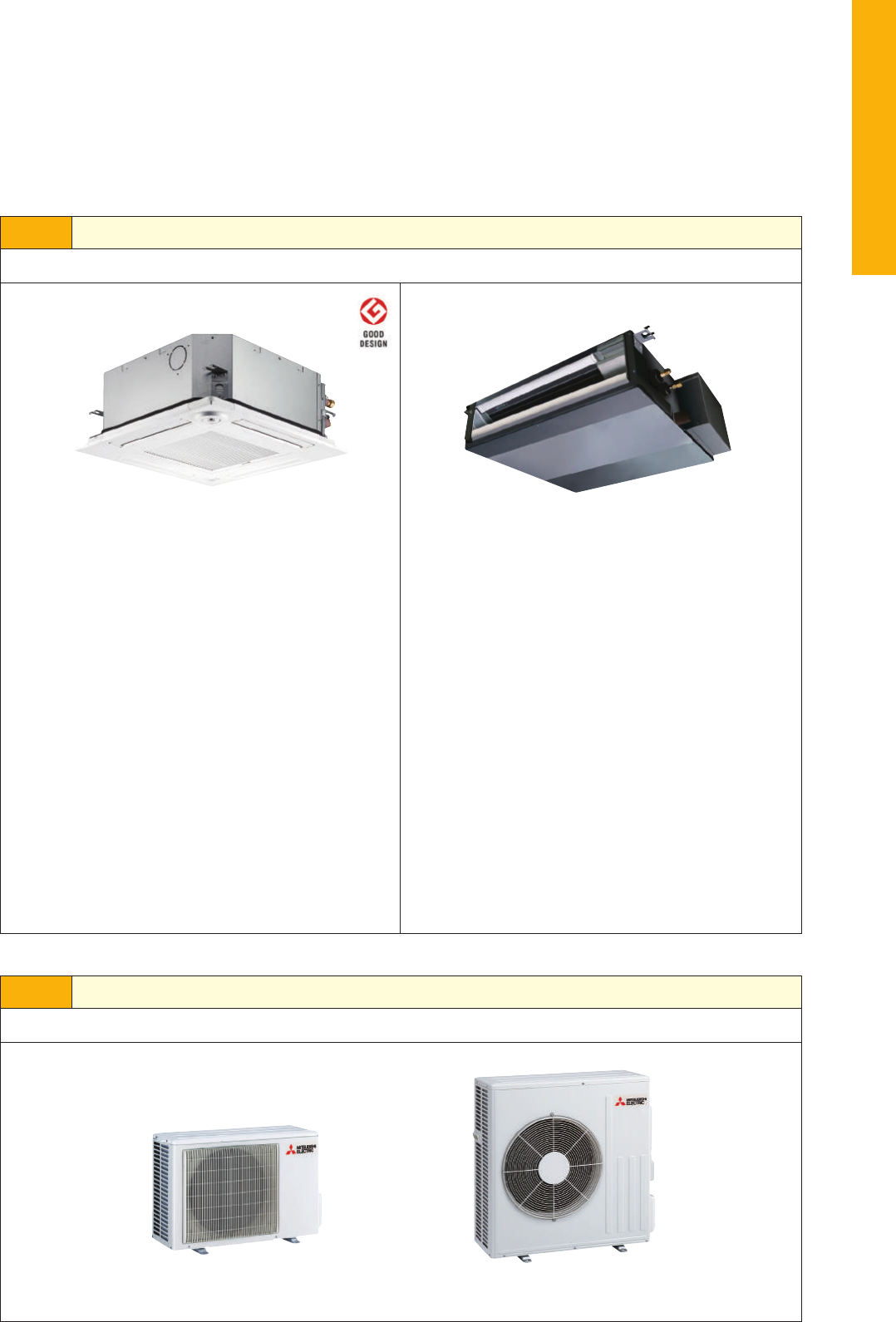
54
SERIES
SELECT INDOOR UNIT
SELECTION
Series line-up consists of two types of indoor units.
Choose the model that best matches room conditions.
Select the optimal unit and capacity required to match room construction and air conditioning requirements.
SELECT OUTDOOR UNIT
There is one outdoor unit for respective indoor units.
✽
To conrm compatibility with the MXZ Series multi-type system, refer to the MXZ Series page.
Units without Remote Controller
SEZ-KD25VAQ
SEZ-KD35VAQ
SEZ-KD50VAQ
SEZ-KD60VAQ
SEZ-KD71VAQ
*
Requires PAR-32MAA or PAC-YT52CRA remote controller.
Units with Wireless Remote Controller
SEZ-KD25VAL
SEZ-KD35VAL
SEZ-KD50VAL
SEZ-KD60VAL
SEZ-KD71VAL
SUZ-KA25/35VA5 SUZ-KA50/60/71VA5
STEP 1
STEP 2
Units without Remote Controller
SLZ-KF25VA2
SLZ-KF35VA2
SLZ-KF50VA2
SLZ-KF60VA2
*
Requires PAR-32MAA or PAC-YT52CRA
or PAR-SL97A-E remote controller.
Grilles
SLP-2FA (only panel)
SLP-2FAL (with Signal Receiver)
SLP-2FAE (with 3D i-see Sensor)
SLP-2FALE (with 3D i-see Sensor and Signal Receiver)
SLP-2FALM (with Wireless Remote Controller)
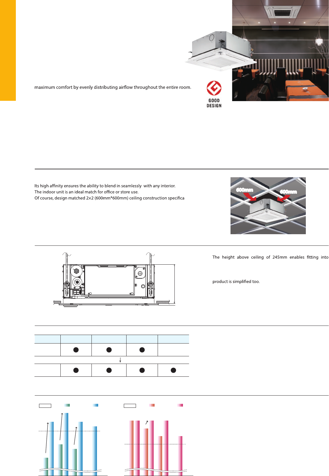
55
SLZ
SERIES
Compact, lightweight ceiling cassette units with 4-way air outlets provide
SLZ-KF60VA.TH
Flow angle,cooling at 20°C (ceiling height 2.7m)
Height (m)
Floor distribution (m)
*Vane angle: Horizontal
(m/s)
2.7
2
1
0
4 3 2 1 0
0.5
1.0
2.0
Corner panel Control box cover
Temporary hanging hook
The structure of the panel has been revised and is now equipped with a
-
porary panel installation.
No need to remove screws
Installation is possible without removing the screws for control box
simply loosen them. This eliminates the risk of losing screws.
SLZ-KA: up to 500mm
SLZ-KF: up to 850mm
Lineup
New design
The height above ceiling of 245mm
25
SLZ-KA
5035 60
6.0kW has been introduced to expand the lineup. The diverse
selection enables the best solution for both customer and
location.
narrow ceiling space. Installation is simple, even when the ceil-
ing spaces are narrow to make the ceilings higher.
Of course, in addition to our products, replacing competitors’
The straight-line form introduced has resulted in a beautiful square design.
-
tions.
As the result of using a larger drain pan, the maximum drain lifting height has
compared to the existing model.
Easy installation
Drain lift
SLZ-KF
Energy-saving Performance
Quietness
The sound level has been reduced by 2-4dB thanks to the introduction
of a 3D turbo fan, for quieter and more comfortable air conditioning.
The energy-saving performance increased approximately
10%, achleving a SEER rating of A
++
.
[SEER]
2.5
kW
3.5
kW
5.0
kW
6.0
kW
A
++
(6.1)
SLZ-KF
6.3
5.5
5.8
5.7
6.5
6.3
6.2
Previous model New model
[SCOP]
2.5
kW
3.5
kW
5.0
kW
6.0
kW
A
+
(4.0)
SLZ-KF
4.3 4.3
4.2
4.1
4.3
4.1
4.3
Previous model New model
Previous model New model
SPL
[Lo]
Cooling
SLZ-KF
2.5
kW
3.5
kW
5.0
kW
6.0
kW
29
dB(A)
25
dB(A)
29
dB(A)
25
dB(A)
32
dB(A)
30
dB(A)
27
dB(A)
245mm
600mm
600mm
SLZ-KF25/35/50/60VA2
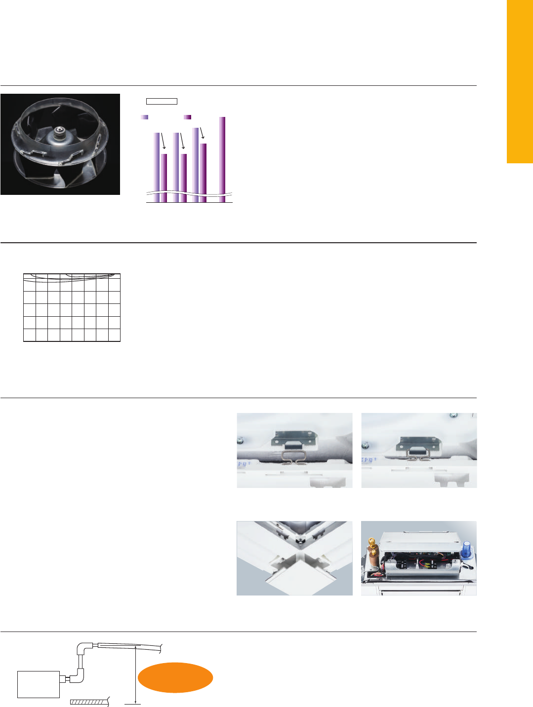
56
SLZ
SERIES
Compact, lightweight ceiling cassette units with 4-way air outlets
provide maximum comfort by evenly distributing airflow throughout
the entire room.
[Airflow distribution]*
SLZ-KF60VA.TH
Flow angle,cooling at 20°C (ceiling height 2.7m)
Height (m)
Floor distribution (m)
*Vane angle: Horizontal
(m/s)
2.7
2
1
0
4 3 2 1 0
0.5
1.0
2.0
■
Corner panel
■
Control box cover
Temporary hanging hook
The structure of the panel has been revised and is now equipped
with a temporary hanging hook. This has improved work efficiency
during temporary panel installation.
No need to remove screws
Installation is possible without removing the screws for control box
simply loosen them. This eliminates the risk of losing screws.
SLZ-KA: up to 500mm
SLZ-KF : up to 850mm
Lineup
New design
The height above ceiling of 245mm
SLZ-KF25/35/50/60VA
25
SLZ-KA
5035 60
6.0kW has been introduced to expand the lineup. The
diverse selection enables the best solution for both
customer and location.
The height above ceiling of 245mm enables fitting into
narrow ceiling space. Installation is simple, even when
the ceiling spaces are narrow to make the ceilings higher.
Of course, in addition to our products, replacing competi-
tors’ product is simplified too.
The straight-line form introduced has resulted in a beautiful square design.
Its high affinity ensures the ability to blend in seamlessly with any interior.
The indoor unit is an ideal match for office or store use.
Of course, design matched 2×2 (600mm*600mm) ceiling construction
specifications.
As the result of using a larger drain pan, the maximum drain lifting height has
been increased from 500mm to 850mm, greatly enhancing construction
flexibility compared to the existing model.
Easy installation
Drain lift
● ● ●
SLZ-KF
● ● ● ●
Energy-saving Performance
Quietness
The new airflow control completely eliminates that uncomfortable drafty-feeling with the introduction
of a horizontal airflow that spreads across the ceiling. The ideal airflow for offices and restaurants.
The sound level has been reduced by 2-4dB thanks to the introduc-
tion of a 3D turbo fan, for quieter and more comfortable air condi-
tioning.
The energy-saving performance increased approximately
10%, achleving a SEER rating of A
++
.
Horizontal Airflow
[SEER]
2.5
kW
3.5
kW
5.0
kW
6.0
kW
A
++
(6.1)
SLZ-KF
6.3
5.5
5.8
5.7
6.5
6.3
6.2
Previous model New model
[SCOP]
2.5
kW
3.5
kW
5.0
kW
6.0
kW
A
+
(4.0)
SLZ-KF
4.3 4.3
4.2
4.1
4.3
4.1
4.3
Previous model New model
Previous model New model
SPL
[Lo]
Cooling
SLZ-KF
2.5
kW
3.5
kW
5.0
kW
6.0
kW
29
dB(A)
25
dB(A)
29
dB(A)
25
dB(A)
32
dB(A)
30
dB(A)
27
dB(A)
245mm
600mm
600mm600mm
600mm
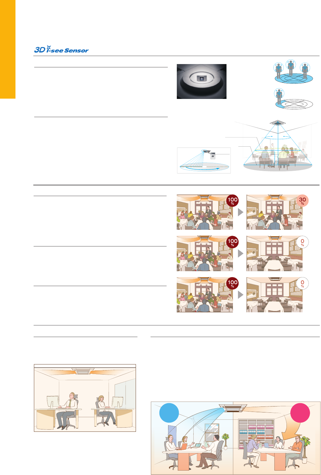
57
Inverter Heat Pump
Cooling
Heating
(Average
Season)
Operating Current (max)
Indoor
Unit
Outdoor
Unit
Ext.
Piping
Guaranteed Operating Range
[Outdoor]
Source
Outdoor (V/Phase/Hz)
Capacity
Total Input
Design Load
Annual Electricity Consumption*
2
SEER
Capacity
Total Input
Design Load
Declared Capacity
Back Up Heating Capacity
Annual Electricity Consumption*
2
SCOP
Input
Operating Current (max)
Dimensions <Panel>
Weight <Panel>
Air Volume [Lo-Mid-Hi]
Sound Level (SPL) [Lo-Mid-Hi]
Sound Level (PWL)
Dimensions
Weight
Air Volume
Sound Level (SPL)
Sound Level (PWL)
Operating Current (max)
Breaker Size
Diameter
Max. Length
Max. Height
Rated
Min - Max
Rated
Energy Efficiency Class
Rated
Min - Max
Rated
at reference design temperature
at bivalent temperature
at operation limit temperature
Energy Efficiency Class
Rated
H × W × D
H × W × D
Cooling
Heating
Cooling
Cooling
Heating
Liquid / Gas
Out-In
Out-In
Cooling
Heating
kW
kW
kW
kW
kWh/a
kW
kW
kW
kW
kW
kW
kW
kW
kWh/a
kW
A
A
mm
kg
m
3
/min
dB(A)
dB(A)
mm
kg
m
3
/min
m
3
/min
dB(A)
dB(A)
dB(A)
A
A
mm
m
m
o
C
o
C
Outdoor power supply
230 / Single / 50
R410A*
1
SLZ-KF25VA2
SUZ-KA25VA5
2.6
1.5 - 3.2
0.684
2.6
144
6.3
A
++
3.2
1.3 - 4.2
0.886
2.2
2.0 (–10°C)
2.0 (–7°C)
2.0 (–10°C)
0.2
716
4.3
A
+
7.2
0.02
0.20
245-570-570 <10-625-625>
15 <3>
6.5 - 7.5 - 8.5
25 - 28 - 31
48
550 - 800 - 285
30
32.6
34.7
47
48
58
7.0
10
6.35 / 9.52
20
12
–10 ~ +46
–10 ~ +24
3.5
1.4 - 3.9
0.972
3.5
188
6.5
A
++
4.0
1.7 - 5.0
1.108
2.6
2.3 (–10°C)
2.3 (–7°C)
2.3 (–10°C)
0.3
845
4.3
A
+
8.4
0.02
0.24
245-570-570 <10-625-625>
15 <3>
6.5 - 8.0 - 9.5
25 - 30 - 34
51
550 - 800 - 285
35
36.3
34.8
49
50
62
8.2
10
6.35 / 9.52
20
12
–10 ~ +46
–10 ~ +24
5.6
2.3 - 6.5
1.767
5.6
316
6.2
A
++
6.4
2.5 - 7.4
2.278
4.6
4.0 (–10°C)
4.0 (–7°C)
4.0 (–10°C)
0.4
1572
4.1
A
+
14.4
0.04
0.43
245-570-570 <10-625-625>
15 <3>
7.5 - 11.5 - 13.0
32 - 40 - 43
60
880 - 840 - 330
50
40.9
49.2
55
55
65
14.0
20
6.35 / 15.88
30
30
–15 ~ +46
–10 ~ +24
4.6
2.3 - 5.2
1.394
4.6
256
6.3
A
++
5.0
1.7 - 6.0
1.558
3.6
3.2 (–10°C)
3.2 (–7°C)
3.2 (–10°C)
0.4
1172
4.3
A
+
12.3
0.03
0.32
245-570-570 <10-625-625>
15 <3>
7.0 - 9.0 - 11.5
27 - 34 - 39
56
880 - 840 - 330
54
44.6
44.6
52
52
65
12.0
20
6.35 / 12.7
30
30
–15 ~ +46
–10 ~ +24
SLZ-KF35VA2
SUZ-KA35VA5
SLZ-KF50VA2
SUZ-KA50VA5
SLZ-KF60VA2
SUZ-KA60VA5
*1 Refrigerant leakage contributes to climate change. Refrigerant with lower global warming potential (GWP) would contribute less to global warming than a refrigerant with higher GWP, if leaked to the atmosphere.
This appliance contains a refrigerant fluid with a GWP equal to 1975. This means that if 1kg of this refrigerant fluid would be leaked to the atmosphere, the impact on global warming would be 1975 times higher
than 1kg of CO2, over a period of 100 years. Never try to interfere with the refrigerant circuit yourself or disassemble the product yourself and always ask a professional.
*2 Energy consumption based on standard test results. Actual energy consumption will depend on how the appliance is used and where it is located.
Type
Indoor Unit
Outdoor Unit
Refrigerant
Power
Supply
SUZ-KA25/35VA5
SUZ-KA50/60VA
*optional
Heat Caulking
Fixing Method
Optional
VA
Optional
Optional Optional
Wi-Fi
Interface
Indoor Unit Outdoor Unit
SLZ-KF SERIES
*optional
*optional
SLZ-KF25/35/50/60VA
Grilles
SLP-2FA (only panel)
SLP-2FAL (with signal receiver)
SLP-2FAE (with 3D i-see Sensor)
SLP-2FALE (with signal receiver and
3D i-see Sensor)
SLP-2FALM (with Wireless Remote Controller)
Remote Controller
for S SERIES
Detects people’s position
Once the position of a person is detected, the duct angle of the vane
is automatically adjusted in that direction. Each vane can be
independently set to “block wind” or “not block wind” according to
taste.
Detects number of people
3D i-see Sensor detects the number of people in the room and sets
the air-conditioning power accordingly. This make automatic
power-saving operation possible in places where the number of
people entering and exiting is large. Additionally, when the area is
continuously unoccupied, the system switches to a more enhanced
power-saving mode. Depending on the setting, it will save addi-
tional capacity or stop operation altogether.
The 3D i-see Sensor detects the number of people in the room. It
then calculates the occupancy rate based on the maximum number
of people in the room up to that point in time in order to save air-
conditioning power. When the occupancy rate is approximately
30%, air-conditioning power equivalent to 1°C during both cooling
and heating operation is saved. The temperature is controlled
according to the number of people.
When 3D i-see Sensor detects that no one is the room, the system
is switched to a pre-set power-saving mode. If the room remains un-
occupied for more than 60min, air-conditioning power equivalent to
2°C during both cooling and heating operation is saved. This contrib-
utes to preventing waste in terms of heating and cooling.
When the room remains unoccupied for a pre-set period of time, the
air conditioner turns off automatically, thereby providing even
greater power savings. The time until operation is stopped can be
set in intervals of 10min, ranging from 60 to 180 min.
No occupancy Auto-OFF mode
No occupancy energy-saving mode
Room occupancy energy-saving mode
Detects number of people
Cooling Heating
Direct/Indirect settings*
Some people do not like the feel of wind, some want
to be warm from head to toe. People’s likes and dis-
likes vary. With the 3D i-see Sensor, it is possible to
choose to block or not block the wind for each vane.
Seasonal airflow*
<
When cooling
>
Saves energy while keeping a comfort-
able effective temperature by automati-
cally switching between ventilation and
cooling. When a pre-set temperature
is reached, the air conditioning unit
switches to swing fan operation to
maintain the effective temperature.
This clever function contributes to
keeping a comfortable coolness.
<
When heating
>
The air conditioning unit automatically
switches between circulator and heating.
Wasted heat that accumulates near the
ceiling is reused via circulation. When a
pre-set temperature is reached the air con-
ditioner switches from heating to circulator
and blows air in the horizontal direction. It
pushes down the warm air that has gath-
ered near the ceiling to people’s height,
thereby providing smart heating.
Detects people’s position
Room occupancy energy save mode
*PAR-32MAA is required for each setting
1C°
power
savings
No occupancy energy save mode
No occupancy Auto-Off mode
2C°
power
savings
Auto-Off
Detects people’s
position
Detects number
of people
1234 5678
1 2 3 4 5
6 7
8
8 sensors
360°
Detection
360°
Detection
7.2m
2.7m
12m
1.1m
Detects floor
temperature
Detects position
and number of people
Floor surface
*In case of a 2.7m ceiling
*PAR-32MAA is required for each setting.
*PAR-32MAA is required for each setting.
58
Inverter Heat Pump
Cooling
Heating
(Average
Season)
Operating Current (max)
Indoor
Unit
Outdoor
Unit
Ext.
Piping
Guaranteed Operating Range
[Outdoor]
Source
Outdoor (V/Phase/Hz)
Capacity
Total Input
Design Load
Annual Electricity Consumption*
2
SEER
Capacity
Total Input
Design Load
Declared Capacity
Back Up Heating Capacity
Annual Electricity Consumption*
2
SCOP
Input
Operating Current (max)
Dimensions <Panel>
Weight <Panel>
Air Volume [Lo-Mid-Hi]
Sound Level (SPL) [Lo-Mid-Hi]
Sound Level (PWL)
Dimensions
Weight
Air Volume
Sound Level (SPL)
Sound Level (PWL)
Operating Current (max)
Breaker Size
Diameter
Max. Length
Max. Height
Rated
Min - Max
Rated
Energy Efficiency Class
Rated
Min - Max
Rated
at reference design temperature
at bivalent temperature
at operation limit temperature
Energy Efficiency Class
Rated
H × W × D
H × W × D
Cooling
Heating
Cooling
Cooling
Heating
Liquid / Gas
Out-In
Out-In
Cooling
Heating
kW
kW
kW
kW
kWh/a
kW
kW
kW
kW
kW
kW
kW
kW
kWh/a
kW
A
A
mm
kg
m
3
/min
dB(A)
dB(A)
mm
kg
m
3
/min
m
3
/min
dB(A)
dB(A)
dB(A)
A
A
mm
m
m
o
C
o
C
Outdoor power supply
230 / Single / 50
R410A*
1
SLZ-KF25VA2
SUZ-KA25VA5
2.6
1.5 - 3.2
0.684
2.6
144
6.3
A
++
3.2
1.3 - 4.2
0.886
2.2
2.0 (–10°C)
2.0 (–7°C)
2.0 (–10°C)
0.2
716
4.3
A
+
7.2
0.02
0.20
245-570-570 <10-625-625>
15 <3>
6.5 - 7.5 - 8.5
25 - 28 - 31
48
550 - 800 - 285
30
32.6
34.7
47
48
58
7.0
10
6.35 / 9.52
20
12
–10 ~ +46
–10 ~ +24
3.5
1.4 - 3.9
0.972
3.5
188
6.5
A
++
4.0
1.7 - 5.0
1.108
2.6
2.3 (–10°C)
2.3 (–7°C)
2.3 (–10°C)
0.3
845
4.3
A
+
8.4
0.02
0.24
245-570-570 <10-625-625>
15 <3>
6.5 - 8.0 - 9.5
25 - 30 - 34
51
550 - 800 - 285
35
36.3
34.8
49
50
62
8.2
10
6.35 / 9.52
20
12
–10 ~ +46
–10 ~ +24
5.6
2.3 - 6.5
1.767
5.6
316
6.2
A
++
6.4
2.5 - 7.4
2.278
4.6
4.0 (–10°C)
4.0 (–7°C)
4.0 (–10°C)
0.4
1572
4.1
A
+
14.4
0.04
0.43
245-570-570 <10-625-625>
15 <3>
7.5 - 11.5 - 13.0
32 - 40 - 43
60
880 - 840 - 330
50
40.9
49.2
55
55
65
14.0
20
6.35 / 15.88
30
30
–15 ~ +46
–10 ~ +24
4.6
2.3 - 5.2
1.394
4.6
256
6.3
A
++
5.0
1.7 - 6.0
1.558
3.6
3.2 (–10°C)
3.2 (–7°C)
3.2 (–10°C)
0.4
1172
4.3
A
+
12.3
0.03
0.32
245-570-570 <10-625-625>
15 <3>
7.0 - 9.0 - 11.5
27 - 34 - 39
56
880 - 840 - 330
54
44.6
44.6
52
52
65
12.0
20
6.35 / 12.7
30
30
–15 ~ +46
–10 ~ +24
SLZ-KF35VA2
SUZ-KA35VA5
SLZ-KF50VA2
SUZ-KA50VA5
SLZ-KF60VA2
SUZ-KA60VA5
*1 Refrigerant leakage contributes to climate change. Refrigerant with lower global warming potential (GWP) would contribute less to global warming than a refrigerant with higher GWP, if leaked to the atmosphere.
This appliance contains a refrigerant fluid with a GWP equal to 1975. This means that if 1kg of this refrigerant fluid would be leaked to the atmosphere, the impact on global warming would be 1975 times higher
than 1kg of CO2, over a period of 100 years. Never try to interfere with the refrigerant circuit yourself or disassemble the product yourself and always ask a professional.
*2 Energy consumption based on standard test results. Actual energy consumption will depend on how the appliance is used and where it is located.
Type
Indoor Unit
Outdoor Unit
Refrigerant
Power
Supply
SUZ-KA25/35VA5
SUZ-KA50/60VA
*optional
Heat Caulking
Fixing Method
Optional
VA
Optional
Optional Optional
Wi-Fi
Interface
Indoor Unit Outdoor Unit
SLZ-KF SERIES
*optional
*optional
SLZ-KF25/35/50/60VA
Grilles
SLP-2FA (only panel)
SLP-2FAL (with signal receiver)
SLP-2FAE (with 3D i-see Sensor)
SLP-2FALE (with signal receiver and
3D i-see Sensor)
SLP-2FALM (with Wireless Remote Controller)
Remote Controller
for S SERIES
Detects people’s position
Once the position of a person is detected, the duct angle of the vane
is automatically adjusted in that direction. Each vane can be
independently set to “block wind” or “not block wind” according to
taste.
Detects number of people
3D i-see Sensor detects the number of people in the room and sets
the air-conditioning power accordingly. This make automatic
power-saving operation possible in places where the number of
people entering and exiting is large. Additionally, when the area is
continuously unoccupied, the system switches to a more enhanced
power-saving mode. Depending on the setting, it will save addi-
tional capacity or stop operation altogether.
The 3D i-see Sensor detects the number of people in the room. It
then calculates the occupancy rate based on the maximum number
of people in the room up to that point in time in order to save air-
conditioning power. When the occupancy rate is approximately
30%, air-conditioning power equivalent to 1°C during both cooling
and heating operation is saved. The temperature is controlled
according to the number of people.
When 3D i-see Sensor detects that no one is the room, the system
is switched to a pre-set power-saving mode. If the room remains un-
occupied for more than 60min, air-conditioning power equivalent to
2°C during both cooling and heating operation is saved. This contrib-
utes to preventing waste in terms of heating and cooling.
When the room remains unoccupied for a pre-set period of time, the
air conditioner turns off automatically, thereby providing even
greater power savings. The time until operation is stopped can be
set in intervals of 10min, ranging from 60 to 180 min.
No occupancy Auto-OFF mode
No occupancy energy-saving mode
Room occupancy energy-saving mode
Detects number of people
Cooling Heating
Direct/Indirect settings*
Some people do not like the feel of wind, some want
to be warm from head to toe. People’s likes and dis-
likes vary. With the 3D i-see Sensor, it is possible to
choose to block or not block the wind for each vane.
Seasonal airflow*
<
When cooling
>
Saves energy while keeping a comfort-
able effective temperature by automati-
cally switching between ventilation and
cooling. When a pre-set temperature
is reached, the air conditioning unit
switches to swing fan operation to
maintain the effective temperature.
This clever function contributes to
keeping a comfortable coolness.
<
When heating
>
The air conditioning unit automatically
switches between circulator and heating.
Wasted heat that accumulates near the
ceiling is reused via circulation. When a
pre-set temperature is reached the air con-
ditioner switches from heating to circulator
and blows air in the horizontal direction. It
pushes down the warm air that has gath-
ered near the ceiling to people’s height,
thereby providing smart heating.
Detects people’s position
Room occupancy energy save mode
*PAR-32MAA is required for each setting
1C°
power
savings
No occupancy energy save mode
No occupancy Auto-Off mode
2C°
power
savings
Auto-Off
Detects people’s
position
Detects number
of people
1234 5678
1 2 3 4 5
6 7
8
8 sensors
360°
Detection
360°
Detection
7.2m
2.7m
12m
1.1m
Detects floor
temperature
Detects position
and number of people
Floor surface
*In case of a 2.7m ceiling
*PAR-32MAA is required for each setting.
*PAR-32MAA is required for each setting.
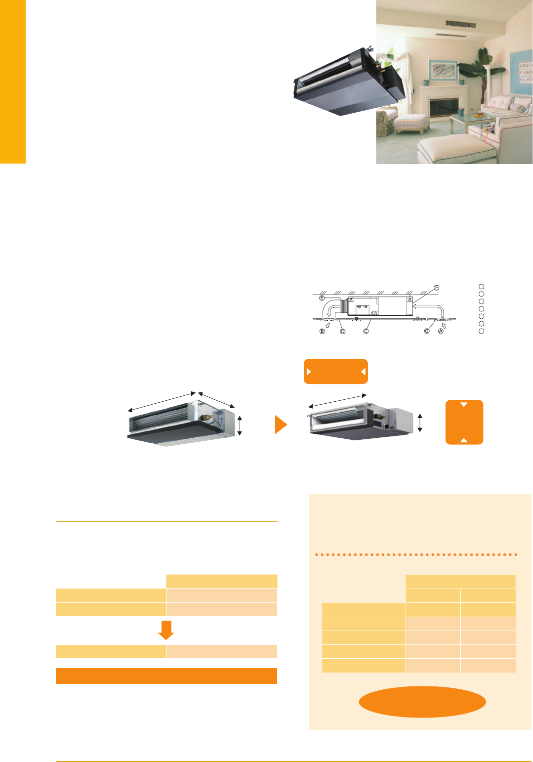
59
SEZ
SERIES
This concealed ceiling-mounted indoor unit series is compact, and fits easily into
rooms with lowered ceilings. Highly reliable energy-saving performance makes it
a best match choice for concealed unit installations.
Compact Ceiling-concealed Units
Only the intake-air grille and outlet vents are visible when using this
ceiling-concealed indoor unit. The rest of the unit is conveniently
hidden in the ceiling cavity, essentially leaving the ceiling and walls
free of bulky looking devices and maintaining a high-class interior
décor. The compact units require minimal space and can be installed
in buildings with lowered ceilings, where exposed units were the
rule in the past.
Increased Selection of Fan Speeds and
Static Pressure Levels
DC fan motor settings have been increased to accommodate more
application needs. Three fan speed settings (Low, Medium and
High) and four static pressure levels (5, 15, 35 and 50Pa) are now
available.
Drain Pump (Optional)
The PAC-KE07DM-E drain pump is now available as an option. With the pump, a drain hose length of up to 550mm can be used,
adding to increased installation possibilities.
Maximum noise
reduced by 7dB
Air inlet
Air outlet
Access door
Ceiling surface
Canvas duct
Air filter
Inlet grille
A
B
C
D
E
F
G
Four Levels Available for All Models
External Static Pressure
35
50
60
71
30dB
31dB
32dB
32dB
23dB
30dB
30dB
30dB
SPL (Low Fan Mode)
SEZ-KASEZ-KD
30 Pa 15Pa
SEZ-KC25VA
SEZ-KA35-71VA
External Static Pressure
5Pa
30/50 Pa
SEZ-KD25-71VA
5/15/35/50Pa
270
200
1100
700
990
SEZ-KA35VA
SEZ-KD35VAQ
Width reduced by
110mm
Dimension Comparison
Height
reduced by
70mm
We’ve lowered the minimum static pressure level, resulting
in less room noise when the optimum static pressure is
selected.
SEZ-KD25-71VAQ/VAL
Inverter Heat Pump
Cooling
Heating
(Average
Season)
Operating Current (max)
Indoor
Unit
Outdoor
Unit
Ext.
Piping
Guaranteed Operating Range
[Outdoor]
Source
Outdoor (V/Phase/Hz)
Capacity
Total Input
Design Load
Annual Electricity Consumption*
2
SEER*
3
Capacity
Total Input
Design Load
Declared Capacity
Back Up Heating Capacity
Annual Electricity Consumption*
2
SCOP*
3
Input
Operating Current (max)
Dimensions <Panel>
Weight <Panel>
Air Volume [Lo-Mid-Hi]
Sound Level (SPL) [Lo-Mid-Hi]
Sound Level (PWL)
Dimensions
Weight
Air Volume
Sound Level (SPL)
Sound Level (PWL)
Operating Current (max)
Breaker Size
Diameter
Max. Length
Max. Height
Rated
Min - Max
Rated
Energy Efficiency Class
Rated
Min - Max
Rated
at reference design temperature
at bivalent temperature
at operation limit temperature
Energy Efficiency Class
Rated
H × W × D
H × W × D
Cooling
Heating
Cooling
Cooling
Heating
Liquid / Gas
Out-In
Out-In
Cooling
Heating
kW
kW
kW
kW
kWh/a
kW
kW
kW
kW
kW
kW
kW
kW
kWh/a
kW
A
A
mm
kg
m
3
/min
dB(A)
External Static Pressure
Pa
dB(A)
mm
kg
m
3
/min
m
3
/min
dB(A)
dB(A)
dB(A)
A
A
mm
m
m
o
C
o
C
Outdoor power supply
230 / Single / 50
R410A*
1
5.1
2.3 - 5.6
1.580
5.1
313
5.7
A
+
6.4
1.7 - 7.2
1.800
4.6
4.1 (–10°C)
4.1 (–7°C)
4.1 (–10°C)
0.5
1653
3.9
A
12.7
0.070
0.7
200 - 990 - 700
23
10 - 13 - 15
5 / 15 / 35 / 50
29 - 33 - 36
57
880 - 840 - 330
54
44.6
44.6
52
52
65
12.0
20
6.35 / 12.7
30
30
–15 ~ +46
–10 ~ +24
2.5
1.5 - 3.2
0.730
2.5
168
5.2
A
2.9
1.3 - 4.5
0.803
2.2
1.9 (–10°C)
1.9 (–7°C)
1.9 (–10°C)
0.3
808
3.8
A
7.4
0.040
0.4
200 - 790 - 700
18
6 - 7 - 9
5 / 15 / 35 / 50
22 - 25 - 29
50
550 - 800 - 285
30
32.6
34.7
47
48
58
7.0
10
6.35 / 9.52
20
12
–10 ~ +46
–10 ~ +24
3.5
1.4 - 3.9
1.010
3.5
219
5.6
A
+
4.2
1.7 - 5.0
1.130
2.8
2.5 (–10°C)
2.5 (–7°C)
2.5 (–10°C)
0.3
979
4.0
A
+
8.7
0.050
0.5
200 - 990 - 700
21
7 - 9 - 11
5 / 15 / 35 / 50
23 - 28 - 33
53
550 - 800 - 285
35
36.3
34.8
49
50
62
8.2
10
6.35 / 9.52
20
12
–10 ~ +46
–10 ~ +24
5.6
2.3 - 6.3
1.740
5.6
376
5.2
A
7.4
2.5 - 8.0
2.200
5.5
4.5 (–10°C)
4.8 (–7°C)
4.5 (–10°C)
1.0
1878
4.1
A
+
14.7
0.070
0.7
200 - 1190 - 700
27
12 - 15 - 18
5 / 15 / 35 / 50
29 - 33 - 37
58
880 - 840 - 330
50
40.9
49.2
55
55
65
14.0
20
6.35 / 15.88
30
30
–15 ~ +46
–10 ~ +24
7.1
2.8 - 8.3
2.210
7.1
477
5.2
A
8.1
2.6 - 10.4
2.268
6.0
5.3 (–10°C)
5.3 (–7°C)
5.3 (–10°C)
0.7
2202
3.8
A
17.0
0.100
0.9
200 - 1190 - 700
27
12 - 16 - 20
5 / 15 / 35 / 50
29 - 34 - 39
60
880 - 840 - 330
53
50.1
48.2
55
55
69
16.1
20
9.52 / 15.88
30
30
–15 ~ +46
–10 ~ +24
SEZ-KD35VAQ/VAL
SUZ-KA35VA5
SEZ-KD50VAQ/VAL
SUZ-KA50VA5
SEZ-KD60VAQ/VAL
SUZ-KA60VA5
SEZ-KD71VAQ/VAL
SUZ-KA71VA5
*1 Refrigerant leakage contributes to climate change. Refrigerant with lower global warming potential (GWP) would contribute less to global warming than a refrigerant with higher GWP, if leaked to the atmosphere.
This appliance contains a refrigerant fluid with a GWP equal to 1975. This means that if 1kg of this refrigerant fluid would be leaked to the atmosphere, the impact on global warming would be 1975 times higher
than 1kg of CO2, over a period of 100 years. Never try to interfere with the refrigerant circuit yourself or disassemble the product yourself and always ask a professional.
*2 Energy consumption based on standard test results. Actual energy consumption will depend on how the appliance is used and where it is located.
*3 SEER/SCOP are measured at ESP 35Pa.
Type
Indoor Unit
Outdoor Unit
Refrigerant
Power
Supply
SEZ-KD25VAQ/VAL
SUZ-KA25VA5
SUZ-KA25/35VA5
SUZ-KA50/60/71VA5
Enclosed in
SEZ-KD25/35/50/60/71VAL
*optional
(for SEZ-KD VAQ)
*optional
(for SEZ-KD VAQ)
Heat Caulking
Fixing Method
Optional
VAQ
Optional Optional Optional Optional
Wi-Fi
Interface
Indoor Unit Outdoor Unit
SEZ-KD SERIES
SEZ-KD25/35/50/60/71VAQ
(
Requires Wired Remote Controller
)
SEZ-KD25/35/50/60/71VAL
(
Wireless Remote Controller is enclosed
)
Remote Controller
Please fill out the requested information
Please fill out the requested information
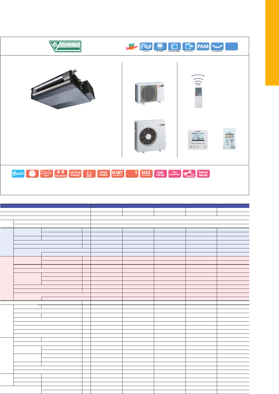
60
SEZ
SERIES
This concealed ceiling-mounted indoor unit series is compact, and fits easily into
rooms with lowered ceilings. Highly reliable energy-saving performance makes it
a best match choice for concealed unit installations.
Compact Ceiling-concealed Units
Only the intake-air grille and outlet vents are visible when using this
ceiling-concealed indoor unit. The rest of the unit is conveniently
hidden in the ceiling cavity, essentially leaving the ceiling and walls
free of bulky looking devices and maintaining a high-class interior
décor. The compact units require minimal space and can be installed
in buildings with lowered ceilings, where exposed units were the
rule in the past.
Increased Selection of Fan Speeds and
Static Pressure Levels
DC fan motor settings have been increased to accommodate more
application needs. Three fan speed settings (Low, Medium and
High) and four static pressure levels (5, 15, 35 and 50Pa) are now
available.
Drain Pump (Optional)
The PAC-KE07DM-E drain pump is now available as an option. With the pump, a drain hose length of up to 550mm can be used,
adding to increased installation possibilities.
Maximum noise
reduced by 7dB
Air inlet
Air outlet
Access door
Ceiling surface
Canvas duct
Air filter
Inlet grille
A
B
C
D
E
F
G
Four Levels Available for All Models
External Static Pressure
35
50
60
71
30dB
31dB
32dB
32dB
23dB
30dB
30dB
30dB
SPL (Low Fan Mode)
SEZ-KASEZ-KD
30 Pa 15Pa
SEZ-KC25VA
SEZ-KA35-71VA
External Static Pressure
5Pa
30/50 Pa
SEZ-KD25-71VA
5/15/35/50Pa
270
200
1100
700
990
SEZ-KA35VA
SEZ-KD35VAQ
Width reduced by
110mm
Dimension Comparison
Height
reduced by
70mm
We’ve lowered the minimum static pressure level, resulting
in less room noise when the optimum static pressure is
selected.
SEZ-KD25-71VAQ/VAL
Inverter Heat Pump
Cooling
Heating
(Average
Season)
Operating Current (max)
Indoor
Unit
Outdoor
Unit
Ext.
Piping
Guaranteed Operating Range
[Outdoor]
Source
Outdoor (V/Phase/Hz)
Capacity
Total Input
Design Load
Annual Electricity Consumption*
2
SEER*
3
Capacity
Total Input
Design Load
Declared Capacity
Back Up Heating Capacity
Annual Electricity Consumption*
2
SCOP*
3
Input
Operating Current (max)
Dimensions <Panel>
Weight <Panel>
Air Volume [Lo-Mid-Hi]
Sound Level (SPL) [Lo-Mid-Hi]
Sound Level (PWL)
Dimensions
Weight
Air Volume
Sound Level (SPL)
Sound Level (PWL)
Operating Current (max)
Breaker Size
Diameter
Max. Length
Max. Height
Rated
Min - Max
Rated
Energy Efficiency Class
Rated
Min - Max
Rated
at reference design temperature
at bivalent temperature
at operation limit temperature
Energy Efficiency Class
Rated
H × W × D
H × W × D
Cooling
Heating
Cooling
Cooling
Heating
Liquid / Gas
Out-In
Out-In
Cooling
Heating
kW
kW
kW
kW
kWh/a
kW
kW
kW
kW
kW
kW
kW
kW
kWh/a
kW
A
A
mm
kg
m
3
/min
dB(A)
External Static Pressure
Pa
dB(A)
mm
kg
m
3
/min
m
3
/min
dB(A)
dB(A)
dB(A)
A
A
mm
m
m
o
C
o
C
Outdoor power supply
230 / Single / 50
R410A*
1
5.1
2.3 - 5.6
1.580
5.1
313
5.7
A
+
6.4
1.7 - 7.2
1.800
4.6
4.1 (–10°C)
4.1 (–7°C)
4.1 (–10°C)
0.5
1653
3.9
A
12.7
0.070
0.7
200 - 990 - 700
23
10 - 13 - 15
5 / 15 / 35 / 50
29 - 33 - 36
57
880 - 840 - 330
54
44.6
44.6
52
52
65
12.0
20
6.35 / 12.7
30
30
–15 ~ +46
–10 ~ +24
2.5
1.5 - 3.2
0.730
2.5
168
5.2
A
2.9
1.3 - 4.5
0.803
2.2
1.9 (–10°C)
1.9 (–7°C)
1.9 (–10°C)
0.3
808
3.8
A
7.4
0.040
0.4
200 - 790 - 700
18
6 - 7 - 9
5 / 15 / 35 / 50
22 - 25 - 29
50
550 - 800 - 285
30
32.6
34.7
47
48
58
7.0
10
6.35 / 9.52
20
12
–10 ~ +46
–10 ~ +24
3.5
1.4 - 3.9
1.010
3.5
219
5.6
A
+
4.2
1.7 - 5.0
1.130
2.8
2.5 (–10°C)
2.5 (–7°C)
2.5 (–10°C)
0.3
979
4.0
A
+
8.7
0.050
0.5
200 - 990 - 700
21
7 - 9 - 11
5 / 15 / 35 / 50
23 - 28 - 33
53
550 - 800 - 285
35
36.3
34.8
49
50
62
8.2
10
6.35 / 9.52
20
12
–10 ~ +46
–10 ~ +24
5.6
2.3 - 6.3
1.740
5.6
376
5.2
A
7.4
2.5 - 8.0
2.200
5.5
4.5 (–10°C)
4.8 (–7°C)
4.5 (–10°C)
1.0
1878
4.1
A
+
14.7
0.070
0.7
200 - 1190 - 700
27
12 - 15 - 18
5 / 15 / 35 / 50
29 - 33 - 37
58
880 - 840 - 330
50
40.9
49.2
55
55
65
14.0
20
6.35 / 15.88
30
30
–15 ~ +46
–10 ~ +24
7.1
2.8 - 8.3
2.210
7.1
477
5.2
A
8.1
2.6 - 10.4
2.268
6.0
5.3 (–10°C)
5.3 (–7°C)
5.3 (–10°C)
0.7
2202
3.8
A
17.0
0.100
0.9
200 - 1190 - 700
27
12 - 16 - 20
5 / 15 / 35 / 50
29 - 34 - 39
60
880 - 840 - 330
53
50.1
48.2
55
55
69
16.1
20
9.52 / 15.88
30
30
–15 ~ +46
–10 ~ +24
SEZ-KD35VAQ/VAL
SUZ-KA35VA5
SEZ-KD50VAQ/VAL
SUZ-KA50VA5
SEZ-KD60VAQ/VAL
SUZ-KA60VA5
SEZ-KD71VAQ/VAL
SUZ-KA71VA5
*1 Refrigerant leakage contributes to climate change. Refrigerant with lower global warming potential (GWP) would contribute less to global warming than a refrigerant with higher GWP, if leaked to the atmosphere.
This appliance contains a refrigerant fluid with a GWP equal to 1975. This means that if 1kg of this refrigerant fluid would be leaked to the atmosphere, the impact on global warming would be 1975 times higher
than 1kg of CO2, over a period of 100 years. Never try to interfere with the refrigerant circuit yourself or disassemble the product yourself and always ask a professional.
*2 Energy consumption based on standard test results. Actual energy consumption will depend on how the appliance is used and where it is located.
*3 SEER/SCOP are measured at ESP 35Pa.
Type
Indoor Unit
Outdoor Unit
Refrigerant
Power
Supply
SEZ-KD25VAQ/VAL
SUZ-KA25VA5
SUZ-KA25/35VA5
SUZ-KA50/60/71VA5
Enclosed in
SEZ-KD25/35/50/60/71VAL
*optional
(for SEZ-KD VAQ)
*optional
(for SEZ-KD VAQ)
Heat Caulking
Fixing Method
Optional
VAQ
Optional Optional Optional Optional
Wi-Fi
Interface
Indoor Unit Outdoor Unit
SEZ-KD SERIES
SEZ-KD25/35/50/60/71VAQ
(
Requires Wired Remote Controller
)
SEZ-KD25/35/50/60/71VAL
(
Wireless Remote Controller is enclosed
)
Remote Controller
Please fill out the requested information
Please fill out the requested information

61
SERIES
SELECT INDOOR UNIT
SELECTION
Line-up includes a selection of eight indoor units and four series of outdoor units.
Easily construct a system that best matches room air conditioning needs.
Select the optimum indoor unit and capacity based on room size and shape.
Power Inverter
Simultaneous Multi-SystemSingle System
Standard Inverter
4-way ceiling-cassette
PLA-ZRP BA
PLA-RP BA
✽ Some indoor units cannot be used with this unit.
SUZ-KA35
✽
Twin
Allows simultaneous operation of
two indoor units on one floor.
Triple
Can cover a large-scale space or dispersed
installation on the same floor.
Quadruple
Realises the optimum temperature
distribution even in a large space.
SELECT OUTDOOR UNIT
The best outdoor unit for the system depends on the combination of functions desired (e.g. energy savings, system capacity, long pipe length).
Check the specifications of the system you need, and then select the optimum outdoor unit series.
Notes: 1) Indoor unit combinations with floor-standing (PS) units and other types are impossible.
2) The distribution pipe listed is required for simultaneous multi-systems.
To confirm compatibility with the MXZ Series, refer to the MXZ Series page.
SELECT COMBINATION
Choose the installation pattern for the indoor units. (In the case of a multi-system, distribution piping is necessary, so please select the necessary piping as well.)
Connectable Combinations for Inverter Units (PUHZ-ZRP / PUHZ-RP / PUHZ-P)
Outdoor Unit Capacity
71
100
125
140
200
250
35 × 2
50 × 2
60 × 2
71 × 2
100 × 2
125 × 2
MSDD-50TR-E
MSDD-50WR-E
Distribution Pipe
Twin
—
—
—
50 × 3
60 × 3
71 × 3
MSDT-111R-E
Indoor Unit Capacity
Triple
—
—
—
—
50 × 4
60 × 4
MSDF-1111R-E
Quadruple
50 : 50 33 : 33 : 33 25 : 25 : 25 : 25
STEP 1
STEP 2
STEP 3
Floor-standing
PSA-KA
Ceiling-suspended
PCA-KAQ
Professional Kitchen
PCA-HAQ
Wall-mounted
PKA-HAL
Wall-mounted
PKA-KAL
Ceiling-concealed
PEA-GAQ
Ceiling-concealed
PEAD-JA
(
L
)
Q
PUHZ-ZRP100/125/140/200/250 PUHZ-ZRP60/71 PUHZ-P100PUHZ-P125/140 SUZ-KA50/60/71
✽
PUHZ-ZRP35/50 PUHZ-P200/250
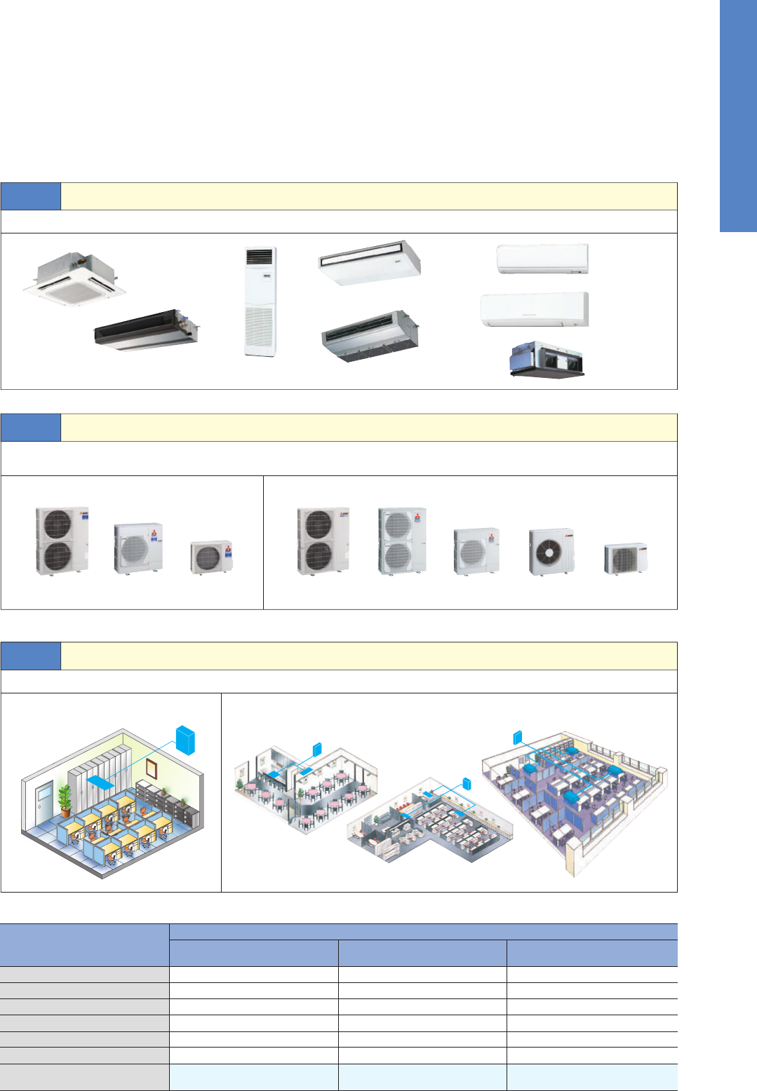
62
SERIES
SELECT INDOOR UNIT
SELECTION
Line-up includes a selection of eight indoor units and four series of outdoor units.
Easily construct a system that best matches room air conditioning needs.
Select the optimum indoor unit and capacity based on room size and shape.
Power Inverter
Simultaneous Multi-SystemSingle System
Standard Inverter
4-way ceiling-cassette
PLA-ZRP BA
PLA-RP BA
✽ Some indoor units cannot be used with this unit.
SUZ-KA35
✽
Twin
Allows simultaneous operation of
two indoor units on one floor.
Triple
Can cover a large-scale space or dispersed
installation on the same floor.
Quadruple
Realises the optimum temperature
distribution even in a large space.
SELECT OUTDOOR UNIT
The best outdoor unit for the system depends on the combination of functions desired (e.g. energy savings, system capacity, long pipe length).
Check the specifications of the system you need, and then select the optimum outdoor unit series.
Notes: 1) Indoor unit combinations with floor-standing (PS) units and other types are impossible.
2) The distribution pipe listed is required for simultaneous multi-systems.
To confirm compatibility with the MXZ Series, refer to the MXZ Series page.
SELECT COMBINATION
Choose the installation pattern for the indoor units. (In the case of a multi-system, distribution piping is necessary, so please select the necessary piping as well.)
Connectable Combinations for Inverter Units (PUHZ-ZRP / PUHZ-RP / PUHZ-P)
Outdoor Unit Capacity
71
100
125
140
200
250
35 × 2
50 × 2
60 × 2
71 × 2
100 × 2
125 × 2
MSDD-50TR-E
MSDD-50WR-E
Distribution Pipe
Twin
—
—
—
50 × 3
60 × 3
71 × 3
MSDT-111R-E
Indoor Unit Capacity
Triple
—
—
—
—
50 × 4
60 × 4
MSDF-1111R-E
Quadruple
50 : 50 33 : 33 : 33 25 : 25 : 25 : 25
STEP 1
STEP 2
STEP 3
Floor-standing
PSA-KA
Ceiling-suspended
PCA-KAQ
Professional Kitchen
PCA-HAQ
Wall-mounted
PKA-HAL
Wall-mounted
PKA-KAL
Ceiling-concealed
PEA-GAQ
Ceiling-concealed
PEAD-JA
(
L
)
Q
PUHZ-ZRP100/125/140/200/250 PUHZ-ZRP60/71 PUHZ-P100PUHZ-P125/140 SUZ-KA50/60/71
✽
PUHZ-ZRP35/50 PUHZ-P200/250
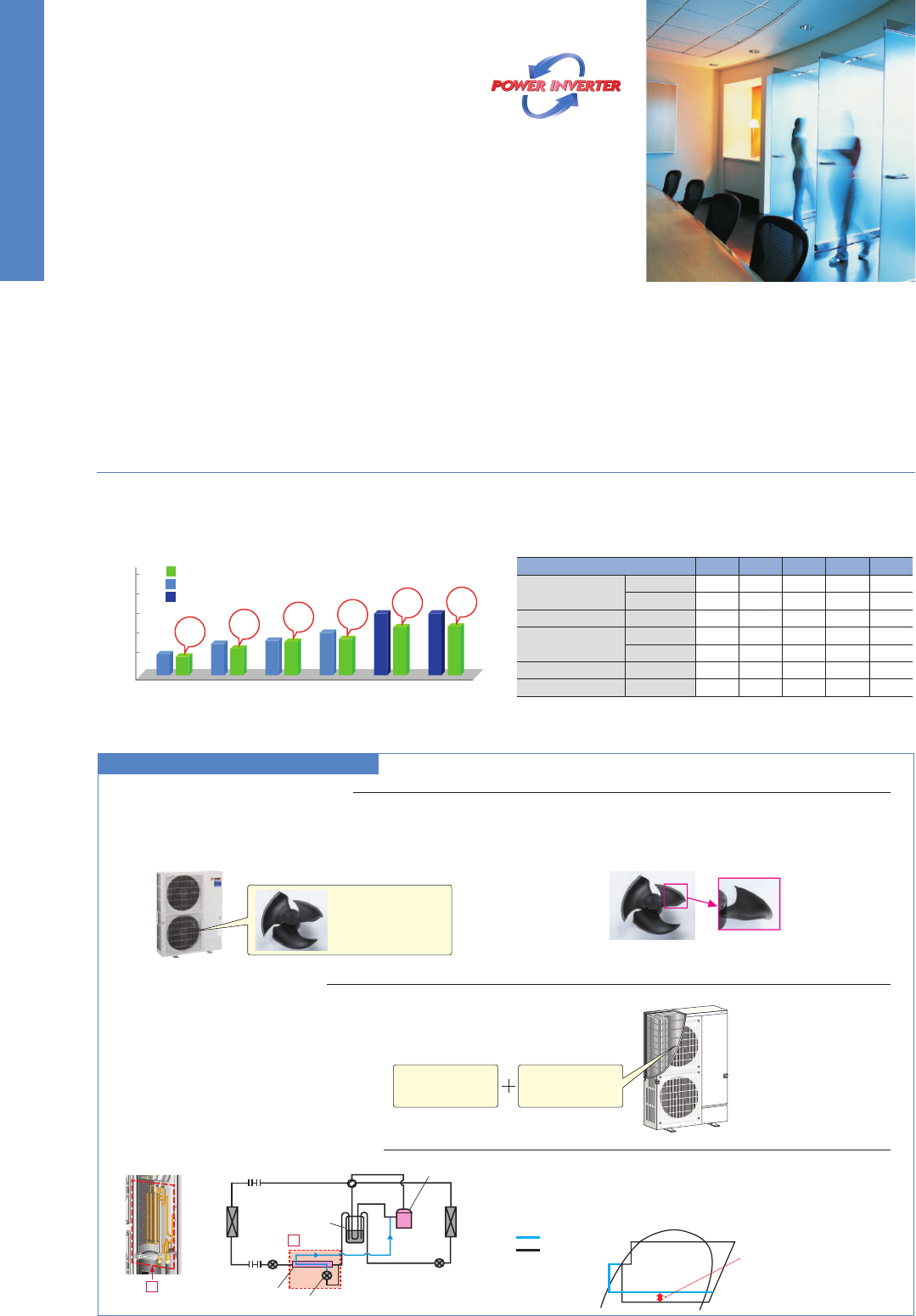
63
Industry-leading Energy Efficiency in New Seasonal Ratings
Industry-leading energy efficiency has been achieved through optimisation of a newly designed compressor and use of the latest energy-saving tech-
nologies. The new Power Inverter Series, designed to realise outstanding seasonal energy-efficiency, achieves high energy-efficiency rankings of A
+
or A
++
for both cooling and heating in most categories. Annual power consumption has been drastically reduced to realise savings in operating cost.
Energy Rank
(Cooling/Heating)
Annual electricity consumption comparison
(PLA-ZRP/PUHZ-ZRP vs PLA-RP/PUHZ-RP)
Series
4-way ceiling cassette
Wall-mounted
Ceiling-suspended
Floor-standing
PLA-ZRP BA
PKA-HAL/KAL
PLA-RP BA
Ceiling-concealed PEAD-JAQ
PCA-KAQ
PCA-HAQ
PSA-KA
Side-flow Outdoor Units
All operating capacities have been unified to the side-flow configu-
ration. Even for locations requiring large capacities, the small foot-
print of these outdoor units enable them to be used anywhere.
Twin Rotary Compressor
(PUHZ-ZRP35/50/60/71)
Powerful yet high-efficiency rotary compressors that make use of
Mitsubishi Electric technologies to achieve industry-leading energy
efficiency under the new seasonal ratings. Annual power consump-
tion has been significantly reduced compared to conventional
units thanks to original Mitsubishi Electric technologies: “Poki-Poki
Motors”, “Heat Caulking Fixing Method, “Divisible Middle Plate”
and “Flat Induction Pipe.”
DC Scroll Compressor
(PUHZ-ZRP100/125/140/200/250)
Our newly developed DC scroll compressor realises higher effi-
ciency at partial load, which accounts for most of the operating
time in both cooling and heating modes. The asymmetrically
shaped scroll contributes to higher SEER and SCOP values and
greatly reduces the annual power consumption. Compression effi-
ciency is also improved through optimised compression and reduc-
tion of refrigerant pressure loss.
3-phase Power-supply Inverter
(100–250)
Incorporation of a 3-phase power-supply realises a dramatic reduc-
tion in operating current. This special technology is equipped in out-
door units to ensure compliance with electromagnetic compatibility
regulations in Europe.
Power Inverter
Our new Power Inverter Series is designed to achieve industry-leading seasonal
energy-efficiency through use of new technologies and high-performance com-
pressor. Installation is now even easier thanks to outdoor units with a side-flow con-
figuration, a maximum piping length of 120m and pipe-replacement technologies.
Fan rear edge
Fan opening of 550mm <100-250>
The opening for the fan in the outdoor unit is 550mm in diameter. By exchanging
heat more efficiently, this will contribute to energy-saving and low noise level.
High-density heat exchanger <100–250>
ZRP 100-250 use 7.94mm-diameter pipe. The high-density heat exchanger con-
tributes to efficient heat exchange and reduces the amount of refrigerant used,
which is better for the environment.
Improved fan <100–250>
A newly designed fan has been adopted, increasing airflow capacity and reducing
operation noise.
Highly efficient fan for outdoor unit
Highly efficient heat exchanger
Increasing the pressure of the
refrigerant sent to the compressor
reduces the compression load
w/ HIC circuit
w/o HIC circuit
A HIC circuit has been added to improve energy efficiency during cooling opera-
tion. Liquid refrigerant is rerouted, transformed into a gas state and injected back
into the system to increase overall pressure of the refrigerant being sent to the
compressor, thereby reducing the load on the compressor and raising efficiency.
Heat Interchanger (HIC) Added
<140>
The opening for the fan
in the outdoor unit is
550mm in diameter.
ADV
ANCED ENERGY
-SA
VING TECHNOLOGIES
SERIES
Heat Interchanger (HIC)
LEV B
LEV C
LEV A
Heat
interchanger
(HIC)
A
A
Indoor
HEX
Outdoor
HEX
Power
receiver
Compressor
Cooling operation
2 lines, 64 columns
(ZRP100–140)
3 lines, 64 columns
(ZRP200–250)
PUHZ-ZRP100/125/140/
200/250
PUHZ-ZRP60/71PUHZ-ZRP35/50
Countermeasure for Problem 1 Countermeasure for Problem 2
No Need to Clean at the Time of System Renewal*
Chloride residue builds up in existing pipes and becomes a source of trouble. In addition, the iron particles and slime produced as a result of
compressor failure lead to problems. To counter this, various original Mitsubishi Electric technologies have been combined to enable the intro-
duction of “cleaning-free pipe reuse.”
Cleaning-free Pipe Reuse Technology
Ability to use existing piping reduces pipe waste and replacement time
Technology 2
Friction Reduction (moving parts in compressor)
Friction inside the compressor is reduced by using an
original Mitsubishi Electric technology called the “Heat
Caulking Fixing Method” or coating the edge of the blade
in the scroll compressor, thereby suppressing the increase
in temperature that causes refrigerant oil deterioration.
*Cautions when using existing piping
•When removing an old air conditioning unit, please make sure to perform the pump-down process and recover the refrigerant and refrigerant oil.
•
Check to ensure that the piping diameter and thickness match Mitsubishi Electric specifications.
•Check to ensure that the flare is compatible with R410A.
Wide strainer
Technology 1
Original High-quality Filtration
Our original high-quality filtration device called the “wide strainer”
is equipped inside the refrigerant inlet and outlet pipe. The “wide
strainer” traps iron particles and realises cleaning-free pipe reuse.
In addition, improvements to the metal used in the bearings of
our new scroll compressors realise more robust units
.
Why can’t existing piping be used?
Cleaning pipe or replacement with new pipe is required
Mitsubishi Electric’s Original Replacement Technologies
Existing piping can be used without cleaning
Result
35V
A
++
/A
++
A
++
/A
+
A
+
/A
A
++
/A
+
–
–
A
+
/A
+
50V
A
++
/A
++
A
+
/A
+
A/A
+
A
+
/A
+
–
–
A
+
/A
+
60V
A
++
/A
+
A
+
/A
A
++
/A
+
A
++
/A
+
–
–
A
++
/A
+
71V
A
++
/A
+
A
++
/A
+
A
++
/A
+
A
++
/A
+
A
+
/A
A
++
/A
+
A
+
/A
100V
A
++
/A
++
A
++
/A
+
A
++
/A
+
A
+
/A
–
A
+
/A
+
A
+
/A
+
✽
The ErP Directive (Lot 10) applies to air conditioners of rated capacity up to 12kW.
✽
Results are based on our own simulations. Actual power consumption
may vary depending on how and where the units are used.
R22 refrigerant R410A refrigerant
Accelerated deterioration
of refrigerant oil
Problem
High heat generated during
operation
Problem
Chloride residue
Increased chloride residue
Iron particles and slime
Refrigerant circuit malfunc-
tions and causes failure
At time of renewal
At time of
compressor failure
35
PLA-ZRP/PUHZ-ZRP
PLA-RP/SUZ-KA
50 60 71
Rated Capacity
100V 100Y
2
%
saving
[kWh/annum]
0
200
400
600
800
1000
PLA-RP/PUHZ-P
12
%
saving
15
%
saving
14
%
saving
23
%
saving
21
%
saving
<Cooling>
Operating current comparison
(for combinations using 4-way ceiling cassettes)
3-phase
1-phase
Max.
Breaker size
Max.
Breaker size
8.7
16
27.2
32
10.3
16
27.3
32
12.1
16
29.1
40
PUHZ-ZRP100YKA2PUHZ-ZRP125YKA2 PUHZ-ZRP140YKA2
Power Supply
PUHZ-ZRP100VKA2PUHZ-ZRP125VKA2 PUHZ-ZRP140VKA2
Power Supply
Long Pipe Length
The maximum piping length is 100m*, enabling wide-ranging layout
possibilities for unit installation.
PUHZ-ZRP35/50
PUHZ-ZRP60/71
PUHZ-ZRP100/125/140
PUHZ-ZRP200/250
Max. Height Difference
30m
30m
30m
30m
Max. Pipe LengthModel
50m
50m
75m
100m
When the total control/power cable length exceeds 80m, separate power sources are
required for the indoor and outdoor units. (An optional power-supply terminal kit is needed
for indoor units with no power-supply terminal block.)
*PUHZ-ZRP200/250 only
64
Industry-leading Energy Efficiency in New Seasonal Ratings
Industry-leading energy efficiency has been achieved through optimisation of a newly designed compressor and use of the latest energy-saving tech-
nologies. The new Power Inverter Series, designed to realise outstanding seasonal energy-efficiency, achieves high energy-efficiency rankings of A
+
or A
++
for both cooling and heating in most categories. Annual power consumption has been drastically reduced to realise savings in operating cost.
Energy Rank
(Cooling/Heating)
Annual electricity consumption comparison
(PLA-ZRP/PUHZ-ZRP vs PLA-RP/PUHZ-RP)
Series
4-way ceiling cassette
Wall-mounted
Ceiling-suspended
Floor-standing
PLA-ZRP BA
PKA-HAL/KAL
PLA-RP BA
Ceiling-concealed PEAD-JAQ
PCA-KAQ
PCA-HAQ
PSA-KA
Side-flow Outdoor Units
All operating capacities have been unified to the side-flow configu-
ration. Even for locations requiring large capacities, the small foot-
print of these outdoor units enable them to be used anywhere.
Twin Rotary Compressor
(PUHZ-ZRP35/50/60/71)
Powerful yet high-efficiency rotary compressors that make use of
Mitsubishi Electric technologies to achieve industry-leading energy
efficiency under the new seasonal ratings. Annual power consump-
tion has been significantly reduced compared to conventional
units thanks to original Mitsubishi Electric technologies: “Poki-Poki
Motors”, “Heat Caulking Fixing Method, “Divisible Middle Plate”
and “Flat Induction Pipe.”
DC Scroll Compressor
(PUHZ-ZRP100/125/140/200/250)
Our newly developed DC scroll compressor realises higher effi-
ciency at partial load, which accounts for most of the operating
time in both cooling and heating modes. The asymmetrically
shaped scroll contributes to higher SEER and SCOP values and
greatly reduces the annual power consumption. Compression effi-
ciency is also improved through optimised compression and reduc-
tion of refrigerant pressure loss.
3-phase Power-supply Inverter
(100–250)
Incorporation of a 3-phase power-supply realises a dramatic reduc-
tion in operating current. This special technology is equipped in out-
door units to ensure compliance with electromagnetic compatibility
regulations in Europe.
Power Inverter
Our new Power Inverter Series is designed to achieve industry-leading seasonal
energy-efficiency through use of new technologies and high-performance com-
pressor. Installation is now even easier thanks to outdoor units with a side-flow con-
figuration, a maximum piping length of 120m and pipe-replacement technologies.
Fan rear edge
Fan opening of 550mm <100-250>
The opening for the fan in the outdoor unit is 550mm in diameter. By exchanging
heat more efficiently, this will contribute to energy-saving and low noise level.
High-density heat exchanger <100–250>
ZRP 100-250 use 7.94mm-diameter pipe. The high-density heat exchanger con-
tributes to efficient heat exchange and reduces the amount of refrigerant used,
which is better for the environment.
Improved fan <100–250>
A newly designed fan has been adopted, increasing airflow capacity and reducing
operation noise.
Highly efficient fan for outdoor unit
Highly efficient heat exchanger
Increasing the pressure of the
refrigerant sent to the compressor
reduces the compression load
w/ HIC circuit
w/o HIC circuit
A HIC circuit has been added to improve energy efficiency during cooling opera-
tion. Liquid refrigerant is rerouted, transformed into a gas state and injected back
into the system to increase overall pressure of the refrigerant being sent to the
compressor, thereby reducing the load on the compressor and raising efficiency.
Heat Interchanger (HIC) Added
<140>
The opening for the fan
in the outdoor unit is
550mm in diameter.
ADV
ANCED ENERGY
-SA
VING TECHNOLOGIES
SERIES
Heat Interchanger (HIC)
LEV B
LEV C
LEV A
Heat
interchanger
(HIC)
A
A
Indoor
HEX
Outdoor
HEX
Power
receiver
Compressor
Cooling operation
2 lines, 64 columns
(ZRP100–140)
3 lines, 64 columns
(ZRP200–250)
PUHZ-ZRP100/125/140/
200/250
PUHZ-ZRP60/71PUHZ-ZRP35/50
Countermeasure for Problem 1 Countermeasure for Problem 2
No Need to Clean at the Time of System Renewal*
Chloride residue builds up in existing pipes and becomes a source of trouble. In addition, the iron particles and slime produced as a result of
compressor failure lead to problems. To counter this, various original Mitsubishi Electric technologies have been combined to enable the intro-
duction of “cleaning-free pipe reuse.”
Cleaning-free Pipe Reuse Technology
Ability to use existing piping reduces pipe waste and replacement time
Technology 2
Friction Reduction (moving parts in compressor)
Friction inside the compressor is reduced by using an
original Mitsubishi Electric technology called the “Heat
Caulking Fixing Method” or coating the edge of the blade
in the scroll compressor, thereby suppressing the increase
in temperature that causes refrigerant oil deterioration.
*Cautions when using existing piping
•When removing an old air conditioning unit, please make sure to perform the pump-down process and recover the refrigerant and refrigerant oil.
•
Check to ensure that the piping diameter and thickness match Mitsubishi Electric specifications.
•Check to ensure that the flare is compatible with R410A.
Wide strainer
Technology 1
Original High-quality Filtration
Our original high-quality filtration device called the “wide strainer”
is equipped inside the refrigerant inlet and outlet pipe. The “wide
strainer” traps iron particles and realises cleaning-free pipe reuse.
In addition, improvements to the metal used in the bearings of
our new scroll compressors realise more robust units
.
Why can’t existing piping be used?
Cleaning pipe or replacement with new pipe is required
Mitsubishi Electric’s Original Replacement Technologies
Existing piping can be used without cleaning
Result
35V
A
++
/A
++
A
++
/A
+
A
+
/A
A
++
/A
+
–
–
A
+
/A
+
50V
A
++
/A
++
A
+
/A
+
A/A
+
A
+
/A
+
–
–
A
+
/A
+
60V
A
++
/A
+
A
+
/A
A
++
/A
+
A
++
/A
+
–
–
A
++
/A
+
71V
A
++
/A
+
A
++
/A
+
A
++
/A
+
A
++
/A
+
A
+
/A
A
++
/A
+
A
+
/A
100V
A
++
/A
++
A
++
/A
+
A
++
/A
+
A
+
/A
–
A
+
/A
+
A
+
/A
+
✽
The ErP Directive (Lot 10) applies to air conditioners of rated capacity up to 12kW.
✽
Results are based on our own simulations. Actual power consumption
may vary depending on how and where the units are used.
R22 refrigerant R410A refrigerant
Accelerated deterioration
of refrigerant oil
Problem
High heat generated during
operation
Problem
Chloride residue
Increased chloride residue
Iron particles and slime
Refrigerant circuit malfunc-
tions and causes failure
At time of renewal
At time of
compressor failure
35
PLA-ZRP/PUHZ-ZRP
PLA-RP/SUZ-KA
50 60 71
Rated Capacity
100V 100Y
2
%
saving
[kWh/annum]
0
200
400
600
800
1000
PLA-RP/PUHZ-P
12
%
saving
15
%
saving
14
%
saving
23
%
saving
21
%
saving
<Cooling>
Operating current comparison
(for combinations using 4-way ceiling cassettes)
3-phase
1-phase
Max.
Breaker size
Max.
Breaker size
8.7
16
27.2
32
10.3
16
27.3
32
12.1
16
29.1
40
PUHZ-ZRP100YKA2PUHZ-ZRP125YKA2 PUHZ-ZRP140YKA2
Power Supply
PUHZ-ZRP100VKA2PUHZ-ZRP125VKA2 PUHZ-ZRP140VKA2
Power Supply
Long Pipe Length
The maximum piping length is 100m*, enabling wide-ranging layout
possibilities for unit installation.
PUHZ-ZRP35/50
PUHZ-ZRP60/71
PUHZ-ZRP100/125/140
PUHZ-ZRP200/250
Max. Height Difference
30m
30m
30m
30m
Max. Pipe LengthModel
50m
50m
75m
100m
When the total control/power cable length exceeds 80m, separate power sources are
required for the indoor and outdoor units. (An optional power-supply terminal kit is needed
for indoor units with no power-supply terminal block.)
*PUHZ-ZRP200/250 only
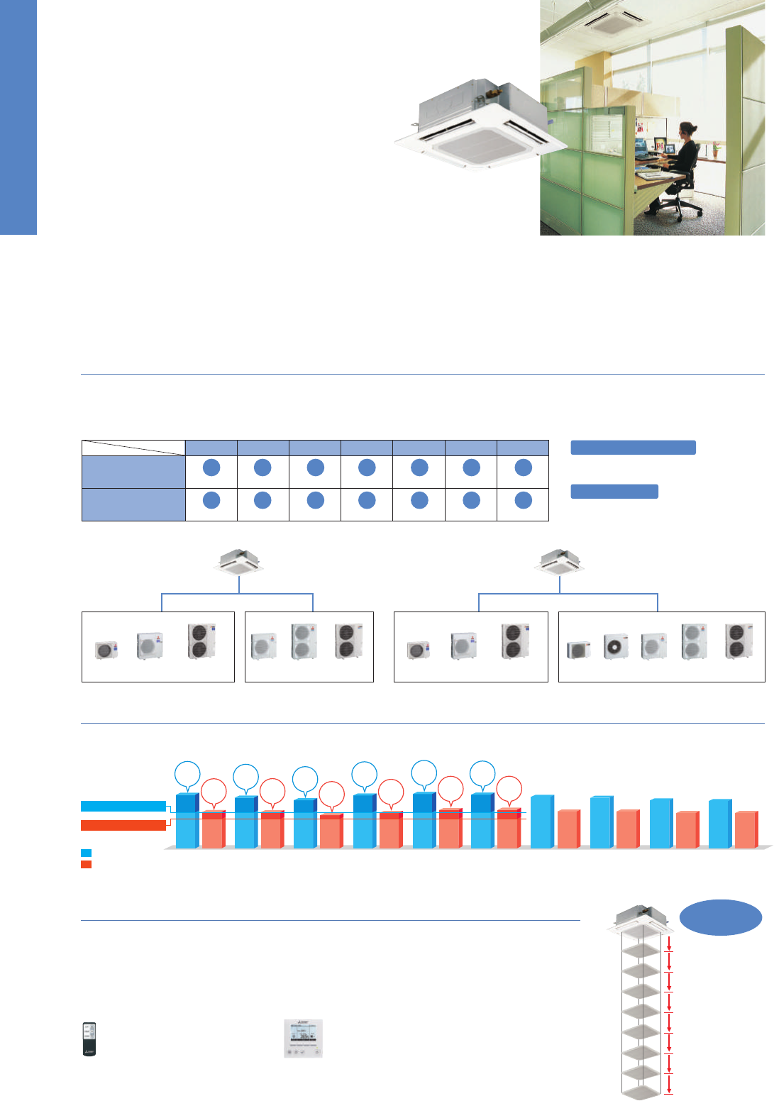
65
New 4-Way Ceiling Cassette
Previous
model
Deluxe 4-way Cassette Line-up
For users seeking even further energy-savings, Mitsubishi Electric offers complete deluxe units (PLA-ZRP) for the complete line-up of models in
this series from 35–140.
Compared to the standard models (PLA-RP), deluxe models provide additional energy-savings, contributing to a significant
reduction in electricity costs.
Automatic Air-speed Adjustment
An automatic air-speed mode that adjusts airflow speed automati-
cally is adopted to maintain comfortable room conditions at all
times. This setting automatically adjusts the air-speed to conditions
that match the room environment.
Horizontal Airflow
A “Horizontal Airflow” function has been
added to reduce drafty-feeling distribution.
Horizontal Airflow prevents cold drafts from
striking the body directly, thereby keeping
the body from becoming over-chilled.
Equipped with High- and Low-ceiling Modes
Units are equipped with high- and low-ceiling operation modes that make it possible to switch the airflow volume to match room height. The ability
to choose the optimum airflow volume makes it possible to optimize the breezy sensation felt throughout the room.
Wave Airflow – Thoroughly warming all corners of the room!
Wave Airflow Operation
“Wave Airflow” is essentially the advanced control of the vanes
directing the airflow from the unit. Blown-air is repeated dispersed
from the unit in horizontal and downward directions at time-lagged
intervals to provide uniform heating throughout the room.
Optimum Airflow
Individual Vane Settings
Optimum airflow settings provide maximum
comfort throughout the room.
In addition to the selection of variable airflow patterns (i.e., 2-,
3- or 4-way), this function allows the independent selection of
vertical airflow levels for each vane, thereby maintaining a com-
fortable room environment with even temperature distribution.
Wide Airflow
Wide-angle outlets distribute airflow
to all corners of the room.
The outlets are larger than those of previous
models and the shape has been improved for
better wide-angle ventilation.
At the start of heating/cooling opera-
tion, the airflow is set to high-speed
to quickly heat/cool the room.
When the room temperature reaches
the desired setting, the airflow speed
is decreased automatically for stable
comfortable heating/cooling operation.
PLA
SERIES
A complete line-up including deluxe units that offer added energy savings. The incorpora-
tion of wide air-outlet and the “i-see Sensor” enhances airflow distribution control, achiev-
ing an enhanced level of comfort throughout the room. The synergy of higher energy
efficiency and more comfortable room environment results in the utmost user satisfaction.
35 50 60 71 100125 140
Deluxe 4-way Cassette
(PLA-ZRP)
Standard 4-way Cassette
(PLA-RP)
■ Line-up
New Heat Exchanger Design
Heat exchanger fin size and pitch have been
changed, raising energy efficiency.
Pre-grooved Piping
High-performance pre-grooved piping is utilised,
increasing the heat exchange area.
■ Key Technologies for Higher Energy Efficiency
PLA-ZRP71BA PLA-ZRP100BA PLA-ZRP125BA
Model
Series
✽ Smudge spots on the ceiling may form where the airflow is not evenly distributed.
[Airflow Distribution]
PLA-RP125BA
Flow angle, cooling at 20°C (ceiling height 3.2m)
(
m/s)
F
l
oor
distr
ibutio
n
(m
)
Hei
g
ht
(m
)
5
4
3
2
1
0
0
1
2
3
3.2
1
.0
2
.
0
3
.0
4
.0
5
.0
Horizontal
Air
flow
A more
horizontal airflow
is achieved using
the new mode.
3.2
m
3.6
m
4.0
m
4.5
m
4.5
m
4.5
m
2.7
m
3.0
m
3.3
m
3.5
m
3.5
m
3.5
m
High-ceiling
setting
Standard
setting
High-ceiling
setting
2.7
m
3.0
m
3.3
m
2.5
m
2.7
m
3.0
m
Low-ceiling
setting
Low-ceiling
setting
Standard
setting
35-71 class 100-140 class
4-Way
3-Way
2-Way
■ Airflow Range
Model
Airflow
pattern
DownwardDownward Downward Downward
Indoor Unit
Indoor Unit
Temperature gap
Uneven temperature distribution
Horizontal Airflow Wave Airflow
Temperature distribution comparison approxi-
mately 20min after turning on a PLA-RP71BA
4-Way ceiling cassette. The measurement point
for comparison is a plane 1.2m above the floor.
Thermograph of Wave Control Effect
Temperature gap is minimized.
Warm air is supplied throughout the room,
minimizing uneven temperature distribution.
3.2m
✽
2.7m
✽
4.5m
✽
✽ 100-140 class
✽ Wave Airflow is possible only when using the heating mode
4-way airflow with
high-ceiling setting
4-way airflow with
standard setting
4-way airflow with
low-ceiling setting
Airflow direction at each vane
can be set using the wired remote
controller. This function is only
available when indoor unit
connects with PUHZ series.
Fixed
Adjustable
Horizontal
Downward
* Optional shuffle placement is required
for 2- and 3-way patterns.
The combination of individual vane setting,
which enables the optimal outlet setting for
each room layout, and the wide airflow function
works to ensure even temperature distribution
throughout each room. The result is uniformly
comfortable air conditioning.
Image of multi-directional
air conditioning
72 airflow patterns
Individual Vane
Setting
Wide Airflow
2-, 3-, 4-way airflow
pattern selection
Gentle
Strong
PLA-ZRP140BAPLA-ZRP60BAPLA-ZRP50BAPLA-ZRP35BA
PLA-RP71BA PLA-RP100BA PLA-RP125BA PLA-RP140BA2PLA-RP60BAPLA-RP50BAPLA-RP35BA
PUHZ-ZRP100/125/140/
200/250
PUHZ-ZRP60/71
■ Indoor/Outdoor Unit Combinations
Power Inverter Standard Inverter
PUHZ-P125/140
PUHZ-P100
PUHZ-ZRP35/50
PUHZ-P200/250
dummy
Deluxe 4-way Cassette
PLA-ZRP BA
PUHZ-ZRP100/125/140/
200/250
PUHZ-ZRP60/71
Power Inverter Standard Inverter
PUHZ-ZRP35/50
Standard 4-way Cassette
PLA-RP BA
SUZ-KA50/60/71SUZ-KA35
“Rank A
++
/A
+
” Energy Savings Achieved for Deluxe 4-way Cassette
Our new deluxe 4-way cassette indoor units combined with newly designed Power Inverter outdoor units (PUHZ-ZRP) achieve industry-leading
seasonal efficiency for both cooling and heating: all rank A
++
for cooling and A
+
or higher for heating.
PLA-ZRP35/50/60/71/100/125/140BA
PLA-RP35/50/60/71/100/125/140BA
An automatic grille lowering function is avail
able for easy filter maintenance. Special
wired and wireless
remote controllers can be used to lower the grille for maintenance.
The grille can be lowered a maximum of 4m from the ceiling in 8 steps, thus enabling easy cleaning of the air filter. Cleaning of the
filter is an important factor for saving energy.
Automatic Grille Lowering Function (PLP-6BAJ)
Grille Elevation Remote Controller
(comes with the automatic elevation panel)
1.2m
1.6m
2.0m
2.4m
2.8m
3.2m
3.6m
4.0m
Automatic
descent down
to 4m
Wired Remote Controller
PUHZ-P125/140
PUHZ-P100
PUHZ-P200/250
Cooling
Heating
PLA-ZRP35BA
PUHZ-ZRP35VKA
PLA-ZRP50BA
PUHZ-ZRP50VKA
PLA-ZRP60BA
PUHZ-ZRP60VHA
PLA-ZRP71BA
PUHZ-ZRP71VHA
PLA-ZRP100BA
PUHZ-ZRP100VKA2
PLA-ZRP100BA
PUHZ-ZRP100YKA2
PLA-ZRP125BA
PUHZ-ZRP125VKA2
PLA-ZRP125BA
PUHZ-ZRP125YKA2
PLA-ZRP140BA
PUHZ-ZRP140VKA2
PLA-ZRP140BA
PUHZ-ZRP140YKA2
✽
For products with capacity over 10.0kW, SEER/SCOP values are measured based on EN14825. These values are for reference purposes only.
6.4
4.7
6.3
4.7
6.1
4.5
6.0
4.5
6.8
6.4
6.1
6.7
6.9
6.8
4.6
4.2
4.6
4.5
4.8
4.8
SEER
A
++
SCOP
A
++
SEER
A
++
SCOP
A
++
SEER
A
++
SCOP
A
+
SEER
A
++
SCOP
A
+
SEER
A
++
SCOP
A
++
SEER
A
++
SCOP
A
++
Minimum SCOP 3.8
Minimum SEER 4.6
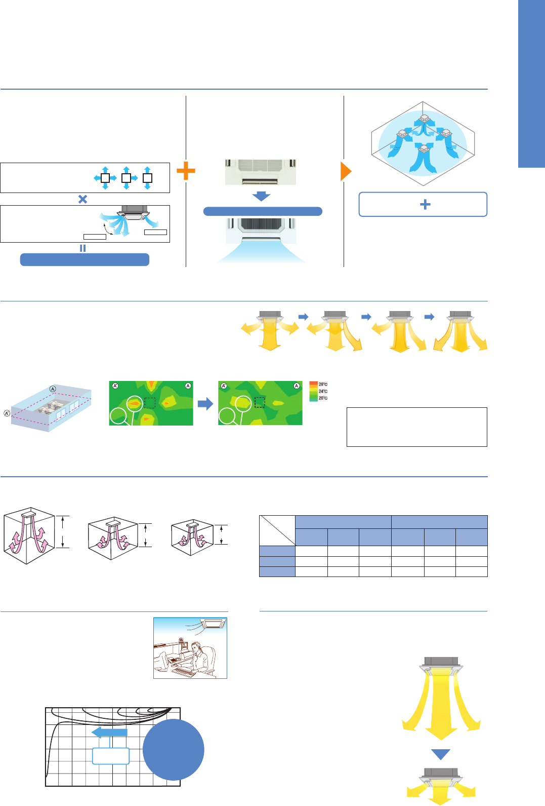
66
New 4-Way Ceiling Cassette
Previous
model
Deluxe 4-way Cassette Line-up
For users seeking even further energy-savings, Mitsubishi Electric offers complete deluxe units (PLA-ZRP) for the complete line-up of models in
this series from 35–140.
Compared to the standard models (PLA-RP), deluxe models provide additional energy-savings, contributing to a significant
reduction in electricity costs.
Automatic Air-speed Adjustment
An automatic air-speed mode that adjusts airflow speed automati-
cally is adopted to maintain comfortable room conditions at all
times. This setting automatically adjusts the air-speed to conditions
that match the room environment.
Horizontal Airflow
A “Horizontal Airflow” function has been
added to reduce drafty-feeling distribution.
Horizontal Airflow prevents cold drafts from
striking the body directly, thereby keeping
the body from becoming over-chilled.
Equipped with High- and Low-ceiling Modes
Units are equipped with high- and low-ceiling operation modes that make it possible to switch the airflow volume to match room height. The ability
to choose the optimum airflow volume makes it possible to optimize the breezy sensation felt throughout the room.
Wave Airflow – Thoroughly warming all corners of the room!
Wave Airflow Operation
“Wave Airflow” is essentially the advanced control of the vanes
directing the airflow from the unit. Blown-air is repeated dispersed
from the unit in horizontal and downward directions at time-lagged
intervals to provide uniform heating throughout the room.
Optimum Airflow
Individual Vane Settings
Optimum airflow settings provide maximum
comfort throughout the room.
In addition to the selection of variable airflow patterns (i.e., 2-,
3- or 4-way), this function allows the independent selection of
vertical airflow levels for each vane, thereby maintaining a com-
fortable room environment with even temperature distribution.
Wide Airflow
Wide-angle outlets distribute airflow
to all corners of the room.
The outlets are larger than those of previous
models and the shape has been improved for
better wide-angle ventilation.
At the start of heating/cooling opera-
tion, the airflow is set to high-speed
to quickly heat/cool the room.
When the room temperature reaches
the desired setting, the airflow speed
is decreased automatically for stable
comfortable heating/cooling operation.
PLA
SERIES
A complete line-up including deluxe units that offer added energy savings. The incorpora-
tion of wide air-outlet and the “i-see Sensor” enhances airflow distribution control, achiev-
ing an enhanced level of comfort throughout the room. The synergy of higher energy
efficiency and more comfortable room environment results in the utmost user satisfaction.
35 50 60 71 100125 140
Deluxe 4-way Cassette
(PLA-ZRP)
Standard 4-way Cassette
(PLA-RP)
■ Line-up
New Heat Exchanger Design
Heat exchanger fin size and pitch have been
changed, raising energy efficiency.
Pre-grooved Piping
High-performance pre-grooved piping is utilised,
increasing the heat exchange area.
■ Key Technologies for Higher Energy Efficiency
PLA-ZRP71BA PLA-ZRP100BA PLA-ZRP125BA
Model
Series
✽ Smudge spots on the ceiling may form where the airflow is not evenly distributed.
[Airflow Distribution]
PLA-RP125BA
Flow angle, cooling at 20°C (ceiling height 3.2m)
(
m/s)
F
l
oor
distr
ibutio
n
(m
)
Hei
g
ht
(m
)
5
4
3
2
1
0
0
1
2
3
3.2
1
.0
2
.
0
3
.0
4
.0
5
.0
Horizontal
Air
flow
A more
horizontal airflow
is achieved using
the new mode.
3.2
m
3.6
m
4.0
m
4.5
m
4.5
m
4.5
m
2.7
m
3.0
m
3.3
m
3.5
m
3.5
m
3.5
m
High-ceiling
setting
Standard
setting
High-ceiling
setting
2.7
m
3.0
m
3.3
m
2.5
m
2.7
m
3.0
m
Low-ceiling
setting
Low-ceiling
setting
Standard
setting
35-71 class 100-140 class
4-Way
3-Way
2-Way
■ Airflow Range
Model
Airflow
pattern
DownwardDownward Downward Downward
Indoor Unit
Indoor Unit
Temperature gap
Uneven temperature distribution
Horizontal Airflow Wave Airflow
Temperature distribution comparison approxi-
mately 20min after turning on a PLA-RP71BA
4-Way ceiling cassette. The measurement point
for comparison is a plane 1.2m above the floor.
Thermograph of Wave Control Effect
Temperature gap is minimized.
Warm air is supplied throughout the room,
minimizing uneven temperature distribution.
3.2m
✽
2.7m
✽
4.5m
✽
✽ 100-140 class
✽ Wave Airflow is possible only when using the heating mode
4-way airflow with
high-ceiling setting
4-way airflow with
standard setting
4-way airflow with
low-ceiling setting
Airflow direction at each vane
can be set using the wired remote
controller. This function is only
available when indoor unit
connects with PUHZ series.
Fixed
Adjustable
Horizontal
Downward
* Optional shuffle placement is required
for 2- and 3-way patterns.
The combination of individual vane setting,
which enables the optimal outlet setting for
each room layout, and the wide airflow function
works to ensure even temperature distribution
throughout each room. The result is uniformly
comfortable air conditioning.
Image of multi-directional
air conditioning
72 airflow patterns
Individual Vane
Setting
Wide Airflow
2-, 3-, 4-way airflow
pattern selection
Gentle
Strong
PLA-ZRP140BAPLA-ZRP60BAPLA-ZRP50BAPLA-ZRP35BA
PLA-RP71BA PLA-RP100BA PLA-RP125BA PLA-RP140BA2PLA-RP60BAPLA-RP50BAPLA-RP35BA
PUHZ-ZRP100/125/140/
200/250
PUHZ-ZRP60/71
■ Indoor/Outdoor Unit Combinations
Power Inverter Standard Inverter
PUHZ-P125/140
PUHZ-P100
PUHZ-ZRP35/50
PUHZ-P200/250
dummy
Deluxe 4-way Cassette
PLA-ZRP BA
PUHZ-ZRP100/125/140/
200/250
PUHZ-ZRP60/71
Power Inverter Standard Inverter
PUHZ-ZRP35/50
Standard 4-way Cassette
PLA-RP BA
SUZ-KA50/60/71SUZ-KA35
“Rank A
++
/A
+
” Energy Savings Achieved for Deluxe 4-way Cassette
Our new deluxe 4-way cassette indoor units combined with newly designed Power Inverter outdoor units (PUHZ-ZRP) achieve industry-leading
seasonal efficiency for both cooling and heating: all rank A
++
for cooling and A
+
or higher for heating.
PLA-ZRP35/50/60/71/100/125/140BA
PLA-RP35/50/60/71/100/125/140BA
An automatic grille lowering function is avail
able for easy filter maintenance. Special
wired and wireless
remote controllers can be used to lower the grille for maintenance.
The grille can be lowered a maximum of 4m from the ceiling in 8 steps, thus enabling easy cleaning of the air filter. Cleaning of the
filter is an important factor for saving energy.
Automatic Grille Lowering Function (PLP-6BAJ)
Grille Elevation Remote Controller
(comes with the automatic elevation panel)
1.2m
1.6m
2.0m
2.4m
2.8m
3.2m
3.6m
4.0m
Automatic
descent down
to 4m
Wired Remote Controller
PUHZ-P125/140
PUHZ-P100
PUHZ-P200/250
Cooling
Heating
PLA-ZRP35BA
PUHZ-ZRP35VKA
PLA-ZRP50BA
PUHZ-ZRP50VKA
PLA-ZRP60BA
PUHZ-ZRP60VHA
PLA-ZRP71BA
PUHZ-ZRP71VHA
PLA-ZRP100BA
PUHZ-ZRP100VKA2
PLA-ZRP100BA
PUHZ-ZRP100YKA2
PLA-ZRP125BA
PUHZ-ZRP125VKA2
PLA-ZRP125BA
PUHZ-ZRP125YKA2
PLA-ZRP140BA
PUHZ-ZRP140VKA2
PLA-ZRP140BA
PUHZ-ZRP140YKA2
✽
For products with capacity over 10.0kW, SEER/SCOP values are measured based on EN14825. These values are for reference purposes only.
6.4
4.7
6.3
4.7
6.1
4.5
6.0
4.5
6.8
6.4
6.1
6.7
6.9
6.8
4.6
4.2
4.6
4.5
4.8
4.8
SEER
A
++
SCOP
A
++
SEER
A
++
SCOP
A
++
SEER
A
++
SCOP
A
+
SEER
A
++
SCOP
A
+
SEER
A
++
SCOP
A
++
SEER
A
++
SCOP
A
++
Minimum SCOP 3.8
Minimum SEER 4.6
67
SERIES SELECTION
Indoor Unit Outdoor Unit
Remote Controller
Power Inverter Series
Indoor Unit
Remote Controller
Standard Inverter Series
Outdoor Unit
For Single
For Multi (Twin/Triple/Quadruple)
SUZ-KA35 PUHZ-P125/140PUHZ-P100SUZ-KA50/60/71
PLZ-ZRP/RP BA Indoor Unit Combinations
Indoor unit combinations shown below are possible.
Indoor Unit Combination
Power Inverter (PUHZ-ZRP)
Distribution Pipe
Standard Inverter (PUHZ-P & SUZ)
Distribution Pipe
For Single
35
35x1
–
35x1
–
50x1
–
50x1
–
60x1
–
60x1
–
71x1
–
71x1
–
100x1
–
100x1
–
125x1
–
125x1
–
140x1
–
140x1
–
–
–
–
–
–
–
–
–
35x2
–
–
50x2
50x2
60x2
60x2
71x2
MSDD-50TR-E
71x2
MSDD-50TR-E
100x2
100x2
MSDD-50WR-E
125x2
MSDD-50WR-E
MSDF-1111R-E
MSDF-1111R-E
125x2
50x3
50x3
60x3
60x3
50x4
50x4
71x3
MSDT-111R-E
71x3
MSDT-111R-E
60x4
60x4
For Twin For Tr iple
For Quadruple
Outdoor Unit Capacity
50 60 71 100 125 140 200 250 71 100 125 140 200 250 140 200 250200 250
PLA-ZRP35/50/60/71/100/125/140BA
PLA-RP35/50/60/71/100/125/140BA
Standard Panel
Automatic Filter Elevation Panel
Standard Panel with “i-see Sensor”
PLP-6BA (only Panel)
PLP-6BALM (with wireless remote controller)
PLP-6BAJ (only Panel)
PLP-6BAE (only Panel)
PLP-6BALME (with wireless remote controller)
Standard Panel
Automatic Filter Elevation Panel
Standard Panel with “i-see Sensor”
PLP-6BA (only Panel)
PLP-6BALM (with wireless remote controller)
PLP-6BAJ (only Panel)
PLP-6BAE (only Panel)
PLP-6BALME (with wireless remote controller)
A comfortable room environment cannot be maintained by monitoring
only the temperature at the ceiling.
Without “i-see Sensor”
Only intake-air temperature
at the ceiling was measured,
tending to overlook uneven
temperature distribution at
floor level.
Equipped with 4-Way
Ceiling “i-see Sensor”
Both the floor temperature
and intake-air temperature
are measured to provide op-
eration that creates a com-
fortable room environment
from ceiling to floor.
DOES HAVING COLD FEET BOTHER YOU?
Heating
Mode
Cooling
Mode
In heating mode, the upper
body gets warm but legs
and feet remain chilly.
When cooling, the legs
and feet get too cold,
chilling the entire body.
Warm air rises
to the ceiling!
Legs and feet
feel cold!
Even though the temperature on
the remote controller is at a preset
temperature, the temperature at
floor level remains cold. As a result,
there’s no feeling of getting warmer.
At the beginning of operation, the
room is nice and cool; but before
long the temperature at floor level
drops, causing the feeling of being
too cold.
11.5m
2.7m
Intake-air temperature sensor
Cassette equipped with
the i-see Sensor measures
upper and lower areas.
360°
sensing
360°
sensing
Intake-air temperature sensor
Cassette without the
i-see Sensor measures temperature
in this area only.
37°C
25°C
13°C
37°C
25°C
13°C
Warm air rises to the ceiling. This causes poor heating at floor level,
leaving legs and feet feeling cold.
The i-see Sensor detects the temperature at the floor while the
Automatic Air-speed Adjustment eliminates uneven temperature
distribution by thoroughly warming the air down to the floor.
Temperature gap minimized
Temperature gap
Room air
warmed to
floor level
When you want the temperature felt to be 20°
Temperature setting: 20°C (w/o i-see Sensor)
Temperature felt: 17°C (floor level 14°C)
Temperature setting: 20°C
(w/ i-see Sensor + Automatic Air-speed Adjustment)
Temperature felt: 20°C (floor level 20°C)
28°C
26.5°C
28°C
26.5°C
32°C
23°C
14°C
32°C
23°C
14°C
The temperature felt drops according to the drop in floor-level
temperature. If the floor-level temperature is not monitored during
long cooling operation, the temperature felt becomes chilly.
Air temperature is adjusted according to the floor temperature to
keep the temperature felt at 28°C.
Temperature setting: 26–27°C (w/o i-see Sensor)
Temperature felt: 26.5°C
Temperature setting: 28°C
(w/ i-see Sensor + Automatic Air-speed Adjustment)
Temperature Felt: 28°C
When you want the temperature felt to be 28°C
Because it takes longer to cool down the
floor-level temperature than the air tem-
perature, a temperature setting of 26 –27°C
is required.
i-see Sensor computes the temperature felt by
monitoring both intake-air temperature and floor-
level temperature. The air temperature is adjusted
at initial start-up, ensuring that the temperature
felt reaches a temperature setting.
Floor-level temperature
Floor-level temperature
At start-up
(approx. 30 min)
At start-up
(approx. 30 min)
Temperature felt drops
No drop in temperature felt
Temperature felt
Temperature felt
Air temperature
(intake-air temperature)
Air temperature
(intake-air temperature)
Temperature distribution
Temperature distribution
After specified time
After specified time
In Heating Mode
In Cooling Mode
Comfortabl
e
without
ex
cess
c
hilliness
The “i-see Sensor” is the answer to your problems!
Joint Lap
35-71
Vector Sine Wave
100-250
DC Rotary
71-140
35-140
Grooved Piping
100-250
Vector-Wave
DC Fan Motor
200/250
DC Scroll
Optional Optional
✽
Enclosed in PLP-6BALM/PLP-6BALME
✽
Enclosed in PLP-6BALM/PLP-6BALME
The “i-see Sensor” is an innovative Mitsubishi Electric technology
that uses a radiation-based sensor to monitor temperature through-
out an entire room. When connected to the air conditioner control
panel, i-see Sensor works to maximize room comfort.
“ ” temperature-sensing
technology improves energy efficiency
and enhances room comfort
■ Corner Panel Only (Option)
PLP-6BAE
PAC-SA1ME-E
or
The i-see Sensor rotates 90° at intervals of
5 sec, accurately measuring the temperature
throughout the room (covering entire floor space).
■ i-see Sensor Operation
90°
rotation
90°
rotation
90°
rotation
5 sec
measurement
5 sec
measurement
5 sec
measurement
5 sec
measurement
■ i-see Sensor Panel
For Single
For Multi
(Twin/Triple/Quadruple)
PUHZ-ZRP100/125/140PUHZ-ZRP60/71
PUHZ-ZRP100/125/140/200/250
PUHZ-P125/140
PUHZ-P200/250PUHZ-P100
PUHZ-ZRP71
PUHZ-ZRP35/50
Optional Optional
25-71
Heat Caulking
Fixing Method
✽
✽
35-140
Grooved Piping
Vector-Wave
35-71
Heat Caulking
Fixing Method
Joint Lap
35-71
Vector Sine Wave
DC Fan Motor
100-250
DC Scroll
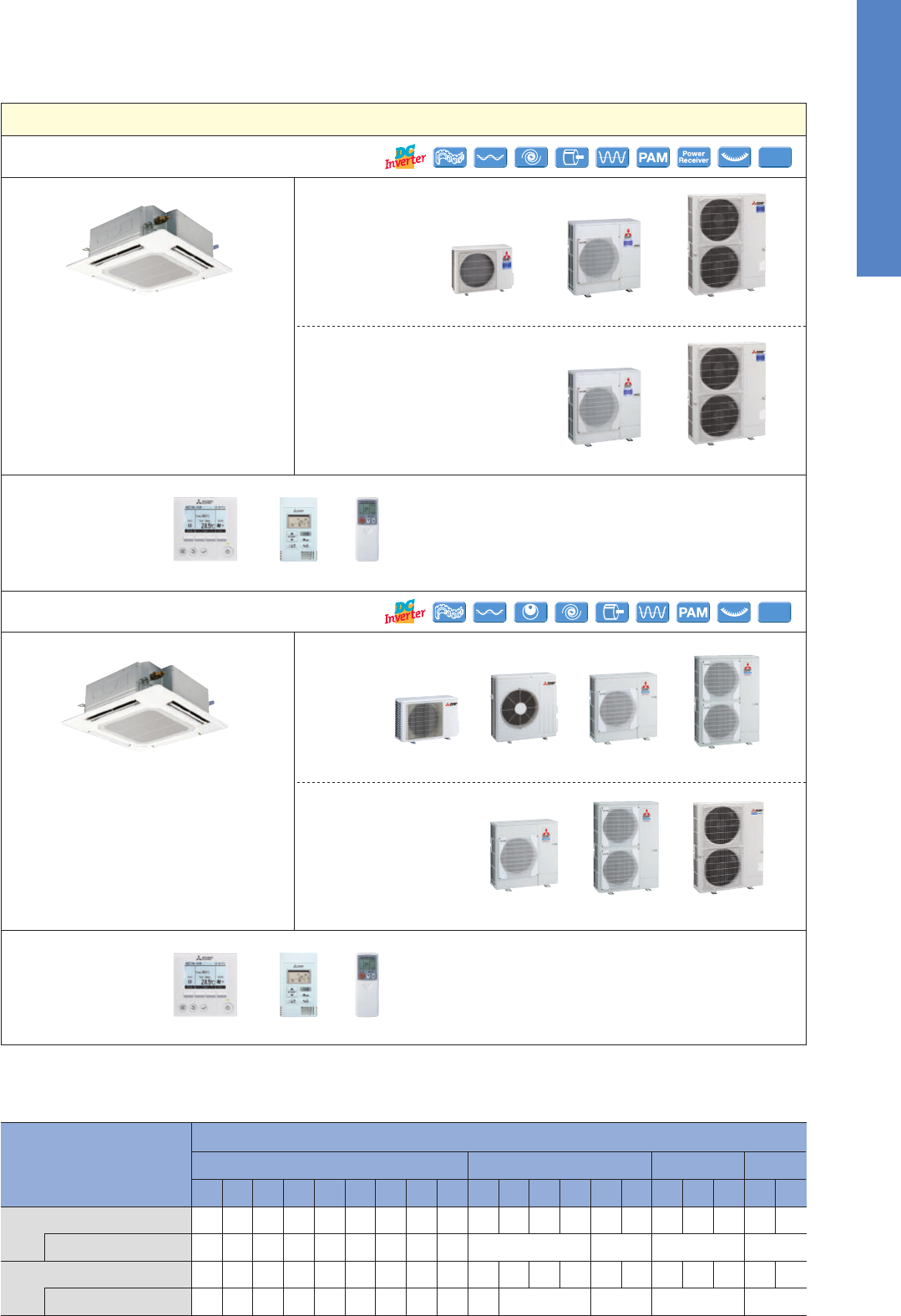
68
SERIES SELECTION
Indoor Unit Outdoor Unit
Remote Controller
Power Inverter Series
Indoor Unit
Remote Controller
Standard Inverter Series
Outdoor Unit
For Single
For Multi (Twin/Triple/Quadruple)
SUZ-KA35 PUHZ-P125/140PUHZ-P100SUZ-KA50/60/71
PLZ-ZRP/RP BA Indoor Unit Combinations
Indoor unit combinations shown below are possible.
Indoor Unit Combination
Power Inverter (PUHZ-ZRP)
Distribution Pipe
Standard Inverter (PUHZ-P & SUZ)
Distribution Pipe
For Single
35
35x1
–
35x1
–
50x1
–
50x1
–
60x1
–
60x1
–
71x1
–
71x1
–
100x1
–
100x1
–
125x1
–
125x1
–
140x1
–
140x1
–
–
–
–
–
–
–
–
–
35x2
–
–
50x2
50x2
60x2
60x2
71x2
MSDD-50TR-E
71x2
MSDD-50TR-E
100x2
100x2
MSDD-50WR-E
125x2
MSDD-50WR-E
MSDF-1111R-E
MSDF-1111R-E
125x2
50x3
50x3
60x3
60x3
50x4
50x4
71x3
MSDT-111R-E
71x3
MSDT-111R-E
60x4
60x4
For Twin For Tr iple
For Quadruple
Outdoor Unit Capacity
50 60 71 100 125 140 200 250 71 100 125 140 200 250 140 200 250200 250
PLA-ZRP35/50/60/71/100/125/140BA
PLA-RP35/50/60/71/100/125/140BA
Standard Panel
Automatic Filter Elevation Panel
Standard Panel with “i-see Sensor”
PLP-6BA (only Panel)
PLP-6BALM (with wireless remote controller)
PLP-6BAJ (only Panel)
PLP-6BAE (only Panel)
PLP-6BALME (with wireless remote controller)
Standard Panel
Automatic Filter Elevation Panel
Standard Panel with “i-see Sensor”
PLP-6BA (only Panel)
PLP-6BALM (with wireless remote controller)
PLP-6BAJ (only Panel)
PLP-6BAE (only Panel)
PLP-6BALME (with wireless remote controller)
A comfortable room environment cannot be maintained by monitoring
only the temperature at the ceiling.
Without “i-see Sensor”
Only intake-air temperature
at the ceiling was measured,
tending to overlook uneven
temperature distribution at
floor level.
Equipped with 4-Way
Ceiling “i-see Sensor”
Both the floor temperature
and intake-air temperature
are measured to provide op-
eration that creates a com-
fortable room environment
from ceiling to floor.
DOES HAVING COLD FEET BOTHER YOU?
Heating
Mode
Cooling
Mode
In heating mode, the upper
body gets warm but legs
and feet remain chilly.
When cooling, the legs
and feet get too cold,
chilling the entire body.
Warm air rises
to the ceiling!
Legs and feet
feel cold!
Even though the temperature on
the remote controller is at a preset
temperature, the temperature at
floor level remains cold. As a result,
there’s no feeling of getting warmer.
At the beginning of operation, the
room is nice and cool; but before
long the temperature at floor level
drops, causing the feeling of being
too cold.
11.5m
2.7m
Intake-air temperature sensor
Cassette equipped with
the i-see Sensor measures
upper and lower areas.
360°
sensing
360°
sensing
Intake-air temperature sensor
Cassette without the
i-see Sensor measures temperature
in this area only.
37°C
25°C
13°C
37°C
25°C
13°C
Warm air rises to the ceiling. This causes poor heating at floor level,
leaving legs and feet feeling cold.
The i-see Sensor detects the temperature at the floor while the
Automatic Air-speed Adjustment eliminates uneven temperature
distribution by thoroughly warming the air down to the floor.
Temperature gap minimized
Temperature gap
Room air
warmed to
floor level
When you want the temperature felt to be 20°
Temperature setting: 20°C (w/o i-see Sensor)
Temperature felt: 17°C (floor level 14°C)
Temperature setting: 20°C
(w/ i-see Sensor + Automatic Air-speed Adjustment)
Temperature felt: 20°C (floor level 20°C)
28°C
26.5°C
28°C
26.5°C
32°C
23°C
14°C
32°C
23°C
14°C
The temperature felt drops according to the drop in floor-level
temperature. If the floor-level temperature is not monitored during
long cooling operation, the temperature felt becomes chilly.
Air temperature is adjusted according to the floor temperature to
keep the temperature felt at 28°C.
Temperature setting: 26–27°C (w/o i-see Sensor)
Temperature felt: 26.5°C
Temperature setting: 28°C
(w/ i-see Sensor + Automatic Air-speed Adjustment)
Temperature Felt: 28°C
When you want the temperature felt to be 28°C
Because it takes longer to cool down the
floor-level temperature than the air tem-
perature, a temperature setting of 26 –27°C
is required.
i-see Sensor computes the temperature felt by
monitoring both intake-air temperature and floor-
level temperature. The air temperature is adjusted
at initial start-up, ensuring that the temperature
felt reaches a temperature setting.
Floor-level temperature
Floor-level temperature
At start-up
(approx. 30 min)
At start-up
(approx. 30 min)
Temperature felt drops
No drop in temperature felt
Temperature felt
Temperature felt
Air temperature
(intake-air temperature)
Air temperature
(intake-air temperature)
Temperature distribution
Temperature distribution
After specified time
After specified time
In Heating Mode
In Cooling Mode
Comfortabl
e
without
ex
cess
chilliness
The “i-see Sensor” is the answer to your problems!
Joint Lap
35-71
Vector Sine Wave
100-250
DC Rotary
71-140
35-140
Grooved Piping
100-250
Vector-Wave
DC Fan Motor
200/250
DC Scroll
Optional Optional
✽
Enclosed in PLP-6BALM/PLP-6BALME
✽
Enclosed in PLP-6BALM/PLP-6BALME
The “i-see Sensor” is an innovative Mitsubishi Electric technology
that uses a radiation-based sensor to monitor temperature through-
out an entire room. When connected to the air conditioner control
panel, i-see Sensor works to maximize room comfort.
“ ” temperature-sensing
technology improves energy efficiency
and enhances room comfort
■ Corner Panel Only (Option)
PLP-6BAE
PAC-SA1ME-E
or
The i-see Sensor rotates 90° at intervals of
5 sec, accurately measuring the temperature
throughout the room (covering entire floor space).
■ i-see Sensor Operation
90°
rotation
90°
rotation
90°
rotation
5 sec
measurement
5 sec
measurement
5 sec
measurement
5 sec
measurement
■ i-see Sensor Panel
For Single
For Multi
(Twin/Triple/Quadruple)
PUHZ-ZRP100/125/140PUHZ-ZRP60/71
PUHZ-ZRP100/125/140/200/250
PUHZ-P125/140
PUHZ-P200/250PUHZ-P100
PUHZ-ZRP71
PUHZ-ZRP35/50
Optional Optional
25-71
Heat Caulking
Fixing Method
✽
✽
35-140
Grooved Piping
Vector-Wave
35-71
Heat Caulking
Fixing Method
Joint Lap
35-71
Vector Sine Wave
DC Fan Motor
100-250
DC Scroll
69
Inverter Heat Pump
POWER INVERTER
PLZ-RP SERIES
POWER INVERTER
PLZ-RP SERIES
Source
kW 3.6
1.6 - 4.5
0.79
–
–
3.6
185
6.8
A
++
4.1
1.6 - 5.2
0.86
–
–
2.4
2.4 (–10°C)
2.4 (–10°C)
2.2 (–11°C)
0
729
4.6
A
++
13.3
0.04
0.28
23 <6>
11 -13-15 -16
27 -28-29 -31
54
43
45.0
45.0
44
46
65
13.0
16
6.35 / 12.7
50
30
–15 ~ +46
–11 ~ +21
Outdoor power supply
VKA
•
VKA2
•
VHA:230 / Single / 50, YKA2:400 / Three / 50
R410A*
1
PLA-
ZRP35BA
PLA-
ZRP50BA
PLA-
ZRP60BA
PLA-ZRP100BA PLA-ZRP125BA PLA-ZRP140BA
PLA-
ZRP71BA
PUHZ-
ZRP35VKA
PUHZ-
ZRP50VKA
PUHZ-
ZRP60VHA
PUHZ-
ZRP71VHA
PUHZ-
ZRP100VKA2
PUHZ-
ZRP100YKA2
PUHZ-
ZRP125VKA2
PUHZ-
ZRP125YKA2
PUHZ-
ZRP140VKA2
PUHZ-
ZRP140YKA2
Type
Outdoor (V/Phase/Hz)
5.0
2.3 - 5.6
1.43
–
–
5.0
272
6.4
A
++
6.0
2.5 - 7.3
1.57
–
–
3.8
3.8 (–10°C)
3.8 (–10°C)
3.7 (–11°C)
0
1162
4.6
A
++
13.3
0.04
0.30
23 <6>
12 -14-16 -18
28 -29-31 -32
55
46
45.0
45.0
44
46
65
13.0
16
6.35 / 12.7
50
30
–15 ~ +46
–11 ~ +21
6.1
2.7 - 6.5
1.78
–
–
6.1
350
6.1
A
++
7.0
2.8 - 8.2
2.04
–
–
4.4
4.4 (–10°C)
4.4 (–10°C)
2.8 (–20°C)
0
1462
4.2
A
+
19.3
0.04
0.30
23 <6>
12 -14-16 -18
28 -29-31 -32
55
67
55.0
55.0
47
48
67
19.0
25
9.52 / 15.88
50
30
–15 ~ +46
–20 ~ +21
7.1
3.3 - 8.1
1.77
–
–
7.1
370
6.7
A
++
8.0
3.5 - 10.2
1.99
–
–
4.7
4.7 (–10°C)
4.7 (–10°C)
3.5 (–20°C)
0
1476
4.5
A
+
19.5
0.05
0.45
25 <6>
17 -19-21 -23
28 -30-34 -36
58
67
55.0
55.0
47
48
67
19.0
25
9.52 / 15.88
50
30
–15 ~ +46
–20 ~ +21
9.5
4.9 - 11.4
2.16
–
–
9.5
484
6.9
A
++
11.2
4.5 - 14.0
2.60
–
–
7.8
7.8 (–10°C)
7.8 (–10°C)
5.8 (–20°C)
0
2275
4.8
A
++
27.2
0.08
0.74
26 <6>
20 -23-26 -30
32 -34-37 -40
65
116
110.0
110.0
49
51
69
26.5
32
9.52 / 15.88
75
30
–15 ~ +46
–20 ~ +21
9.5
4.9 - 11.4
2.16
–
–
9.5
493
6.8
A
++
11.2
4.5 - 14.0
2.60
–
–
7.8
7.8 (–10°C)
7.8 (–10°C)
5.8 (–20°C)
0
2275
4.8
A
++
8.7
0.08
0.74
26 <6>
20 -23-26 -30
32 -34-37 -40
65
123
110.0
110.0
49
51
69
8.0
16
9.52 / 15.88
75
30
–15 ~ +46
–20 ~ +21
12.5
5.5 - 14.0
3.87
3.23
–
12.5
685
6.4
–
14.0
5.0 - 16.0
3.67
3.81
–
9.3
9.3 (–10°C)
9.3 (–10°C)
7.0 (–20°C)
0
2778
4.7
*
4
–
27.3
0.09
0.80
27 <6>
22 -25-28 -31
34 -36-39 -41
66
116
120.0
120.0
50
52
70
26.5
32
9.52 / 15.88
75
30
–15 ~ +46
–20 ~ +21
12.5
5.5 - 14.0
3.87
3.23
–
12.5
695
6.3
–
14.0
5.0 - 16.0
3.67
3.81
–
9.3
9.3 (–10°C)
9.3 (–10°C)
7.0 (–20°C)
0
2778
4.7
*
4
–
10.3
0.09
0.80
27 <6>
22 -25-28 -31
34 -36-39 -41
66
125
120.0
120.0
50
52
70
9.5
16
9.52 / 15.88
75
30
–15 ~ +46
–20 ~ +21
13.4
6.2 - 15.0
4.37
3.07
–
13.4
770
6.1
*
4
–
16.0
5.7 - 18.0
4.70
3.40
–
10.6
10.6 (–10°C)
10.6 (–10°C)
7.9 (–20°C)
0
3324
4.5
*
4
–
29.1
0.12
1.07
27 <6>
24 -26-29 -32
36 -39-42 -44
70
118
120.0
120.0
50
52
70
28.0
40
9.52 / 15.88
75
30
–15 ~ +46
–20 ~ +21
13.4
6.2 - 15.0
4.37
3.07
–
13.4
781
6.0
*
4
–
16.0
5.7 - 18.0
4.70
3.40
–
10.6
10.6 (–10°C)
10.6 (–10°C)
7.9 (–20°C)
0
3324
4.5
*
4
–
14.1
0.12
1.07
27 <6>
24 -26-29 -32
36 -39-42 -44
70
131
120.0
120.0
50
52
70
13.0
16
9.52 / 15.88
75
30
–15 ~ +46
–20 ~ +21
Power
Supply
Capacity
Total Input
Rated
Cooling
Heating
(Average
Season)
Operating Current (max)
Indoor
Unit
Outdoor
Unit
Indoor Unit
Outdoor Unit
Refrigerant
kW
Min - Max
kW
kW
kWh/a
Rated
Rated
EEL Rank
EER
Design Load
kW
Min - Max
kW
Rated
kW
kW
A
Capacity
Total Input
COP
Design Load
kW
kW
kW
kW
kWh/a
kW
Declared Capacity
Back Up Heating Capacity
Annual Electricity Consumption
*
2
SCOP
Input Rated
A
Operating Current (max)
mm
Dimensions <Panel>
kg
Weight <Panel>
kg
Weight
m
3
/min
Air Volume [Lo-Mi2-Mi1-Hi]
dB(A)
Sound Level (SPL) [Lo-Mi2-Mi1-Hi]
dB(A)
Sound Level (PWL)
H × W × D
mm
Dimensions H × W × D
Ext.
Piping
mm
Diameter Liquid / Gas
Guaranteed Operating Range
[Outdoor]
°C
Cooling
*
3
°C
Heating
m
Max. Length Out-In
m
Max. Height Out-In
m
3
/min
Air Volume Cooling
m
3
/min
Heating
dB(A)
dB(A)
dB(A)
Sound Level (SPL)
Cooling
Sound Level (PWL)
Cooling
A
Operating Current (max)
A
Breaker Size
Heating
EEL Rank
at reference design temperature
at bivalent temperature
at operation limit temperature
Energy Efficiency Class
Energy Efficiency Class
SEER
Annual Electricity Consumption
*
2
943 - 950 - 330 (+30)630 - 809 - 300
258 - 840 - 840 <35 - 950 - 950> 298 - 840 - 840 <35 - 950 - 950>
1338 - 1050 - 330 (+40)
Inverter Heat Pump
Source
kW 3.5
1.6 - 4.5
0.88
–
–
3.5
189
6.5
A
++
4.1
1.6 - 5.2
0.96
–
–
2.3
2.3 (–10°C)
2.3 (–10°C)
2.2 (–11°C)
0
750
4.3
A
+
13.2
0.03
0.22
22 <6>
11 -12-13 -15
27 -28-29 -31
54
43
45.0
45.0
44
46
65
13.0
16
6.35 / 12.7
50
30
–15 ~ +46
–11 ~ +21
Outdoor power supply
VKA
•
VKA2
•
VHA:230 / Single / 50, YKA2:400 / Three / 50
R410A*
1
PLA-
RP35BA
PLA-
RP50BA
PLA-
RP60BA
PLA-RP100BA PLA-RP125BA PLA-RP140BA2
PLA-
RP71BA
PUHZ-
ZRP35VKA
PUHZ-
ZRP50VKA
PUHZ-
ZRP60VHA
PUHZ-
ZRP71VHA
PUHZ-
ZRP100VKA2
PUHZ-
ZRP100YKA2
PUHZ-
ZRP125VKA2
PUHZ-
ZRP125YKA2
PUHZ-
ZRP140VKA2
PUHZ-
ZRP140YKA2
Type
Outdoor (V/Phase/Hz)
5.0
2.3 - 5.6
1.43
–
–
5.0
311
5.6
A
+
6.0
2.5 - 7.3
1.82
–
–
3.8
3.8 (–10°C)
3.8 (–10°C)
3.7 (–11°C)
0
1313
4.1
A
+
13.4
0.05
0.36
22 <6>
12 -14-16 -18
28 -29-31 -32
55
46
45.0
45.0
44
46
65
13.0
16
6.35 / 12.7
50
30
–15 ~ +46
–11 ~ +21
6.1
2.7 - 6.5
1.90
–
–
6.1
371
5.7
A
+
7.0
2.8 - 8.2
2.17
–
–
4.4
4.4 (–10°C)
4.4 (–10°C)
2.8 (–20°C)
0
1576
3.9
A
19.4
0.05
0.36
23 <6>
12 -14-16 -18
28 -29-31 -32
55
67
55.0
55.0
47
48
67
19.0
25
9.52 / 15.88
50
30
–15 ~ +46
–20 ~ +21
7.1
3.3 - 8.1
1.87
–
–
7.1
387
6.4
A
++
8.0
3.5 - 10.2
2.21
–
–
4.7
4.7 (–10°C)
4.7 (–10°C)
3.5 (–20°C)
0
1521
4.3
A
+
19.5
0.07
0.51
23 <6>
14 -16-18 -21
28 -30-32 -34
56
67
55.0
55.0
47
48
67
19.0
25
9.52 / 15.88
50
30
–15 ~ +46
–20 ~ +21
9.5
4.9 - 11.4
2.21
–
–
9.5
511
6.5
A
++
11.2
4.5 - 14.0
2.95
–
–
7.8
7.8 (–10°C)
7.8 (–10°C)
5.8 (–20°C)
0
2511
4.3
A
+
27.4
0.14
0.94
25 <6>
20 -23-26 -30
32 -34-37 -40
62
116
110.0
110.0
49
51
69
26.5
32
9.52 / 15.88
75
30
–15 ~ +46
–20 ~ +21
9.5
4.9 - 11.4
2.21
–
–
9.5
522
6.4
A
++
11.2
4.5 - 14.0
2.95
–
–
7.8
7.8 (–10°C)
7.8 (–10°C)
5.8 (–20°C)
0
2511
4.3
A
+
8.9
0.14
0.94
25 <6>
20 -23-26 -30
32 -34-37 -40
62
123
110.0
110.0
49
51
69
8.0
16
9.52 / 15.88
75
30
–15 ~ +46
–20 ~ +21
12.5
5.5 - 14.0
3.99
3.13
–
12.5
875
5.0
*
4
–
14.0
5.0 - 16.0
3.91
3.58
–
9.3
9.3 (–10°C)
9.3 (–10°C)
7.0 (–20°C)
0
3304
3.9
*
4
–
27.5
0.15
1.00
25 <6>
22 -25-28 -31
34 -36-39 -41
63
116
120.0
120.0
50
52
70
26.5
32
9.52 / 15.88
75
30
–15 ~ +46
–20 ~ +21
12.5
5.5 - 14.0
3.99
3.13
–
12.5
886
4.9
*
4
–
14.0
5.0 - 16.0
3.91
3.58
–
9.3
9.3 (–10°C)
9.3 (–10°C)
7.0 (–20°C)
0
3304
3.9
*
4
–
10.5
0.15
1.00
25 <6>
22 -25-28 -31
34 -36-39 -41
63
125
120.0
120.0
50
52
70
9.5
16
9.52 / 15.88
75
30
–15 ~ +46
–20 ~ +21
13.4
6.2 - 15.0
4.40
3.05
–
13.4
849
5.5
*
4
–
16.0
5.7 - 18.0
4.76
3.36
–
10.6
10.6 (–10°C)
10.6 (–10°C)
7.9 (–20°C)
0
3746
4.0
*
4
–
29.1
0.16
1.07
27 <6>
24 -26-29 -32
36 -39-42 -44
70
118
120.0
120.0
50
52
70
28.0
40
9.52 / 15.88
75
30
–15 ~ +46
–20 ~ +21
13.4
6.2 - 15.0
4.40
3.05
–
13.4
860
5.5
*
4
–
16.0
5.7 - 18.0
4.76
3.36
–
10.6
10.6 (–10°C)
10.6 (–10°C)
7.9 (–20°C)
0
3746
4.0
*
4
–
14.1
0.16
1.07
27 <6>
24 -26-29 -32
36 -39-42 -44
70
131
120.0
120.0
50
52
70
13.0
16
9.52 / 15.88
75
30
–15 ~ +46
–20 ~ +21
Power
Supply
Capacity
Total Input
Rated
Cooling
Heating
(Average
Season)
Operating Current (max)
Indoor
Unit
Outdoor
Unit
Indoor Unit
Outdoor Unit
Refrigerant
kW
Min - Max
kW
kW
kWh/a
Rated
Rated
EEL Rank
EER
Design Load
kW
Min - Max
kW
Rated
kW
kW
A
Capacity
Total Input
COP
Design Load
kW
kW
kW
kW
kWh/a
kW
Declared Capacity
Back Up Heating Capacity
Annual Electricity Consumption
*
2
SCOP
Input Rated
A
Operating Current (max)
mm
Dimensions <Panel>
kg
Weight <Panel>
kg
Weight
m
3
/min
Air Volume [Lo-Mi2-Mi1-Hi]
dB(A)
Sound Level (SPL) [Lo-Mi2-Mi1-Hi]
dB(A)
Sound Level (PWL)
H × W × D
mm
Dimensions H × W × D
Ext.
Piping
mm
Diameter Liquid / Gas
Guaranteed Operating Range
[Outdoor]
°C
Cooling
*
3
°C
Heating
m
Max. Length Out-In
m
Max. Height Out-In
m
3
/min
Air Volume Cooling
m
3
/min
Heating
dB(A)
dB(A)
dB(A)
Sound Level (SPL)
Cooling
Sound Level (PWL)
Cooling
A
Operating Current (max)
A
Breaker Size
Heating
EEL Rank
at reference design temperature
at bivalent temperature
at operation limit temperature
Energy Efficiency Class
Energy Efficiency Class
SEER
Annual Electricity Consumption
*
2
943 - 950 - 330 (+30)630 - 809 - 300
258 - 840 - 840 <35 - 950 - 950> 298 - 840 - 840 <35 - 950 - 950>
1338 - 1050 - 330 (+40)
SPLZ-P SERIES
PLZ-P SERIES
*1 Refrigerant leakage contributes to climate change. Refrigerant with lower global warming potential (GWP) would contribute less to global warming than a refrigerant with higher GWP, if leaked to the atmosphere. This appliance
contains a refrigerant fluid with a GWP equal to 1975. This means that if 1kg of this refrigerant fluid would be leaked to the atmosphere, the impact on global warming would be 1975 times higher than 1kg of CO2, over a period
of 100 years. Never try to interfere with the refrigerant circuit yourself or disassemble the product yourself and always ask a professional.
*2 Energy consumption based on standard test results. Actual energy consumption will depend on how the appliance is used and where it is located.
*3 Optional air protection guide is required where ambient temperature is lower than –5°C. *4 SEER/SCOP values are measured based on EN14825. These values are reference purpose only.
Inverter Heat Pump
Source
kW 3.6
1.4 - 3.9
1.090
–
–
3.6
210
6.0
A
+
4.1
1.7 - 5.0
1.040
–
–
2.6
2.3 (–10°C)
2.3 (–7°C)
2.3 (–10°C)
0.3
867
4.2
A
+
8.4
0.03
0.22
22 <6>
11 -12-13 -15
27 -28-29 -31
54
550 - 800 - 285
35
36.3
34.8
49
50
62
8.2
10
6.35 / 9.52
20
12
–10 ~ +46
–10 ~ +24
Outdoor power supply
VA5
•
VHA3
•
VHA4:230 / Single / 50, YHA
•
YHA2:400 / Three / 50
R410A*
1
PLA-
RP35BA
PLA-
RP50BA
PLA-
RP60BA
PLA-RP100BA PLA-RP125BA PLA-RP140BA2
PLA-
RP71BA
SUZ-
KA35VA5
SUZ-
KA50VA5
SUZ-
KA60VA5
SUZ-
KA71VA5
PUHZ-
P100VHA4
PUHZ-
P100YHA2
PUHZ-
P125VHA3
PUHZ-
P125YHA
PUHZ-
P140VHA3
PUHZ-
P140YHA
Type
Outdoor (V/Phase/Hz)
5.5
2.3 - 5.6
1.660
–
–
5.5
321
6.0
A
+
6.0
1.7 - 7.2
1.750
–
–
4.3
3.8 (–10°C)
3.8 (–7°C)
3.8 (–10°C)
0.5
1503
4.0
A
+
12.4
0.05
0.36
22 <6>
12 -14-16 -18
28 -29-31 -32
55
54
44.6
44.6
52
52
65
12.0
20
6.35 / 12.7
30
30
–15 ~ +46
–10 ~ +24
6.1
2.3 - 6.3
1.910
–
–
6.1
355
6.0
A
+
7.0
2.5 - 8.0
2.060
–
–
4.6
4.0 (–10°C)
4.1 (–7°C)
4.0 (–10°C)
0.6
1562
4.1
A
+
14.4
0.05
0.36
23 <6>
12 -14-16 -18
28 -29-31 -32
55
50
40.9
49.2
55
55
65
14.0
20
6.35 / 15.88
30
30
–15 ~ +46
–10 ~ +24
7.1
2.8 - 8.1
2.100
–
–
7.1
429
5.8
A
+
8.0
2.6 - 10.2
2.247
–
–
5.8
4.7 (–10°C)
5.1 (–7°C)
4.7 (–10°C)
1.1
1913
4.3
A
+
16.6
0.07
0.51
23 <6>
14 -16-18- 21
28 -30-32 -34
56
53
50.1
48.2
55
55
69
16.1
20
9.52 / 15.88
30
30
–15 ~ +46
–10 ~ +24
9.4
4.9 - 11.2
3.120
–
–
9.4
628
5.2
A
11.2
4.5 - 12.5
3.280
–
–
8.0
6.3 (–10°C)
7.1 (–7°C)
5.0 (–15°C)
1.7
2945
3.8
A
28.9
0.14
0.94
25 <6>
20 -23-26 -30
32 -34-37 -40
62
75
60.0
60.0
50
54
70
28.0
32
9.52 / 15.88
50
30
–15 ~ +46
–15 ~ +21
9.4
4.9 - 11.2
3.120
–
–
9.4
628
5.2
A
11.2
4.5 - 12.5
3.280
–
–
8.0
6.3 (–10°C)
7.1 (–7°C)
5.0 (–15°C)
1.7
2945
3.8
A
13.9
0.14
0.94
25 <6>
20 -23-26 -30
32 -34-37 -40
62
77
60.0
60.0
50
54
70
13.0
16
9.52 / 15.88
50
30
–15 ~ +46
–15 ~ +21
12.3
5.5 - 14.0
4.090
3.01
B
–
–
–
–
14.0
5.0 - 16.0
4.110
3.41
B
–
–
–
–
–
–
–
–
29.0
0.15
1.00
25 <6>
22 -25-28 -31
34 -36-39 -41
63
99
100.0
100.0
51
55
71
28.0
32
9.52 / 15.88
50
30
–15 ~ +46
–15 ~ +21
12.3
5.5 - 14.0
4.090
3.01
B
–
–
–
–
14.0
5.0 - 16.0
4.110
3.41
B
–
–
–
–
–
–
–
–
14.0
0.15
1.00
25 <6>
22 -25-28 -31
34 -36-39 -41
63
101
100.0
100.0
51
55
71
13.0
16
9.52 / 15.88
50
30
–15 ~ +46
–15 ~ +21
13.6
5.5 - 15.0
5.210
2.61
D
–
–
–
–
16.0
5.0 - 18.0
4.980
3.21
C
–
–
–
–
–
–
–
–
30.5
0.15
1.00
27 <6>
24 -26-29 -32
36 -39-42 -44
70
99
100.0
100.0
52
56
73
29.5
40
9.52 / 15.88
50
30
–15 ~ +46
–15 ~ +21
13.6
5.5 - 15.0
5.210
2.61
D
–
–
–
–
16.0
5.0 - 18.0
4.980
3.21
C
–
–
–
–
–
–
–
–
14.0
0.15
1.00
27 <6>
24 -26-29 -32
36 -39-42 -44
70
101
100.0
100.0
52
56
73
13.0
16
9.52 / 15.88
50
30
–15 ~ +46
–15 ~ +21
Power
Supply
Capacity
Total Input
Rated
Cooling
Heating
(Average
Season)
Operating Current (max)
Indoor
Unit
Outdoor
Unit
Indoor Unit
Outdoor Unit
Refrigerant
kW
Min - Max
kW
kW
kWh/a
Rated
Rated
EEL Rank
EER
Design Load
kW
Min - Max
kW
Rated
kW
kW
A
Capacity
Total Input
COP
Design Load
kW
kW
kW
kW
kWh/a
kW
Declared Capacity
Back Up Heating Capacity
Annual Electricity Consumption
*
2
SCOP
Input Rated
A
Operating Current (max)
mm
Dimensions <Panel>
kg
Weight <Panel>
kg
Weight
m
3
/min
Air Volume [Lo-Mi2-Mi1-Hi]
dB(A)
Sound Level (SPL) [Lo-Mi2-Mi1-Hi]
dB(A)
Sound Level (PWL)
H × W × D
mm
Dimensions H × W × D
Ext.
Piping
mm
Diameter Liquid / Gas
Guaranteed Operating Range
[Outdoor]
°C
Cooling
*
3
°C
Heating
m
Max. Length Out-In
m
Max. Height Out-In
m
3
/min
Air Volume Cooling
m
3
/min
Heating
dB(A)
dB(A)
dB(A)
Sound Level (SPL)
Cooling
Sound Level (PWL)
Cooling
A
Operating Current (max)
A
Breaker Size
Heating
EEL Rank
at reference design temperature
at bivalent temperature
at operation limit temperature
Energy Efficiency Class
Energy Efficiency Class
SEER
Annual Electricity Consumption
*
2
880 - 840 - 330
258 - 840 - 840 <35 - 950 - 950> 298 - 840 - 840 <35 - 950 - 950>
943 - 950 - 330 (+30) 1350 - 950 - 330 (+30)
*1 Refrigerant leakage contributes to climate change. Refrigerant with lower global warming potential (GWP) would contribute less to global warming than a refrigerant with higher GWP, if leaked to the atmosphere. This appliance
contains a refrigerant fluid with a GWP equal to 1975. This means that if 1kg of this refrigerant fluid would be leaked to the atmosphere, the impact on global warming would be 1975 times higher than 1kg of CO2, over a period
of 100 years. Never try to interfere with the refrigerant circuit yourself or disassemble the product yourself and always ask a professional.
*2 Energy consumption based on standard test results. Actual energy consumption will depend on how the appliance is used and where it is located.
*3 Optional air protection guide is required where ambient temperature is lower than –5°C. *4 SEER/SCOP values are measured based on EN14825. These values are reference purpose only.
STANDARD INVERTER
SPLZ-P SERIES
PLZ-P SERIES
STANDARD INVERTER
*1 Refrigerant leakage contributes to climate change. Refrigerant with lower global warming potential (GWP) would contribute less to global warming than a refrigerant with higher GWP, if leaked to the atmosphere. This appliance
contains a refrigerant fluid with a GWP equal to 1975. This means that if 1kg of this refrigerant fluid would be leaked to the atmosphere, the impact on global warming would be 1975 times higher than 1kg of CO2, over a period
of 100 years. Never try to interfere with the refrigerant circuit yourself or disassemble the product yourself and always ask a professional.
*2 Energy consumption based on standard test results. Actual energy consumption will depend on how the appliance is used and where it is located.
*3 Optional air protection guide is required where ambient temperature is lower than –5°C. *4 SEER/SCOP values are measured based on EN14825. These values are reference purpose only.
Inverter Heat Pump
Source
kW 9.4
4.9 - 11.2
3.082
-
-
9.4
610
5.4
A
11.2
4.5 - 12.5
3.137
–
–
8.0
6.3 (–10°C)
7.1 (–7°C)
5.0 (–15°C)
1.7
2800
4.0
A
+
28.7
0.08
0.74
26 <6>
20 - 23 - 26 - 30
32 - 34 - 37 - 40
65
75
60.0
60.0
50
54
70
28.0
32
9.52 / 15.88
50
30
–15 ~ +46
–15 ~ +21
9.4
4.9 - 11.2
3.082
–
–
9.4
610
5.4
A
11.2
4.5 - 12.5
3.137
–
–
8.0
6.3 (–10°C)
7.1 (–7°C)
5.0 (–15°C)
1.7
2800
4.0
A
+
13.7
0.08
0.74
26 <6>
20 - 23 - 26 - 30
32 - 34 - 37 - 40
65
77
60.0
60.0
50
54
70
13.0
16
9.52 / 15.88
50
30
–15 ~ +46
–15 ~ +21
12.3
5.5 - 14.0
4.020
3.06
B
–
–
–
–
14.0
5.0 - 16.0
3.989
3.51
B
–
–
–
–
–
–
–
–
28.8
0.09
0.80
27 <6>
22 - 25 - 28 - 31
34 - 36 - 39 - 41
66
99
100.0
100.0
51
55
71
28.0
32
9.52 / 15.88
50
30
–15 ~ +46
–15 ~ +21
12.3
5.5 - 14.0
4.020
3.06
B
–
–
–
–
14.0
5.0 - 16.0
3.989
3.51
B
–
–
–
–
–
–
–
–
13.8
0.09
0.80
27 <6>
22 - 25 - 28 - 31
34 - 36 - 39 - 41
66
101
100.0
100.0
51
55
71
13.0
16
9.52 / 15.88
50
30
–15 ~ +46
–15 ~ +21
13.6
5.5 - 15.0
5.171
2.63
D
–
–
–
–
16.0
5.0 - 18.0
4.938
3.24
C
–
–
–
–
–
–
–
–
30.6
0.12
1.07
27 <6>
24 - 26 - 29 - 32
36 - 39 - 42 - 44
70
99
100.0
100.0
52
56
73
29.5
40
9.52 / 15.88
50
30
–15 ~ +46
–15 ~ +21
13.6
5.5 - 15.0
5.171
2.63
D
–
–
–
–
16.0
5.0 - 18.0
4.938
3.24
C
–
–
–
–
–
–
–
–
14.1
0.12
1.07
27 <6>
24 - 26 - 29 - 32
36 - 39 - 42 - 44
70
101
100.0
100.0
52
56
73
13.0
16
9.52 / 15.88
50
30
–15 ~ +46
–15 ~ +21
Outdoor power supply
230 / Single / 50 400 / Three / 50 230 / Single / 50 400 / Three / 50 230 / Single / 50 400 / Three / 50
R410A*
1
PLA-ZRP100BA PLA-ZRP125BA PLA-ZRP140BA
PUHZ-P100VHA4 PUHZ-P100YHA2 PUHZ-P125VHA3 PUHZ-P125YHA PUHZ-P140VHA3 PUHZ-P140YHA
Type
Outdoor (V/Phase/Hz)
Power
Supply
Capacity
Total Input
Rated
Cooling
Heating
(Average
Season)
Operating Current (max)
Indoor
Unit
Outdoor
Unit
Indoor Unit
Outdoor Unit
Refrigerant
kW
Min - Max
kW
kW
kWh/a
Rated
Rated
EEL Rank
EER
Design Load
kW
Min - Max
kW
Rated
kW
kW
A
Capacity
Total Input
COP
Design Load
kW
kW
kW
kW
kWh/a
kW
Declared Capacity
Back Up Heating Capacity
Annual Electricity Consumption
*
2
SCOP
Input Rated
A
Operating Current (max)
mm
Dimensions <Panel>
kg
Weight <Panel>
kg
Weight
m
3
/min
Air Volume [Lo-Mi2-Mi1-Hi]
dB(A)
Sound Level (SPL) [Lo-Mi2-Mi1-Hi]
dB(A)
Sound Level (PWL)
H × W × D
mm
Dimensions H × W × D
Ext.
Piping
mm
Diameter Liquid / Gas
Guaranteed Operating Range
[Outdoor]
°C
Cooling
*
3
°C
Heating
m
Max. Length Out-In
m
Max. Height Out-In
m
3
/min
Air Volume Cooling
m
3
/min
Heating
dB(A)
dB(A)
dB(A)
Sound Level (SPL)
Cooling
Sound Level (PWL)
Cooling
A
Operating Current (max)
A
Breaker Size
Heating
EEL Rank
at reference design temperature
at bivalent temperature
at operation limit temperature
Energy Efficiency Class
Energy Efficiency Class
SEER
Annual Electricity Consumption
*
2
*1 Refrigerant leakage contributes to climate change. Refrigerant with lower global warming potential (GWP) would contribute less to global warming than a refrigerant with higher GWP, if leaked to the atmosphere. This appliance
contains a refrigerant fluid with a GWP equal to 1975. This means that if 1kg of this refrigerant fluid would be leaked to the atmosphere, the impact on global warming would be 1975 times higher than 1kg of CO
2, over a period
of 100 years. Never try to interfere with the refrigerant circuit yourself or disassemble the product yourself and always ask a professional.
*2 Energy consumption based on standard test results. Actual energy consumption will depend on how the appliance is used and where it is located.
*3 Optional air protection guide is required where ambient temperature is lower than –5°C. *4 SEER/SCOP values are measured based on EN14825. These values are reference purpose only.
298 - 840 - 840 <35 - 950 - 950>
943 - 950 - 330 (+30) 1350 - 950 - 330 (+30)
Optional Optional Optional
60-140V/200/250
OptionalOptional Optional
Optional Optional
Optional Optional Optional
60-140V/200/250
OptionalOptional Optional
OptionalOptional
Wi-Fi
Interface
Optional
PUHZ SUZ
OptionalOptionalOptional
PUHZ
Optional Optional
PUHZ
PUHZPUHZ
PUHZ
PUHZ
Optional
Optional Optional
Wi-Fi
Interface
Optional
PUHZ SUZ
OptionalOptionalOptional
PUHZ
Optional Optional
PUHZ
PUHZPUHZ
PUHZ
PUHZ
Optional
Optional Optional
Wi-Fi
Interface
Wi-Fi
Interface
Please fill out the requested information
Please fill out the requested information
Please fill out the requested information
Please fill out the requested information
70
Inverter Heat Pump
POWER INVERTER
PLZ-RP SERIES
POWER INVERTER
PLZ-RP SERIES
Source
kW 3.6
1.6 - 4.5
0.79
–
–
3.6
185
6.8
A
++
4.1
1.6 - 5.2
0.86
–
–
2.4
2.4 (–10°C)
2.4 (–10°C)
2.2 (–11°C)
0
729
4.6
A
++
13.3
0.04
0.28
23 <6>
11 -13-15 -16
27 -28-29 -31
54
43
45.0
45.0
44
46
65
13.0
16
6.35 / 12.7
50
30
–15 ~ +46
–11 ~ +21
Outdoor power supply
VKA
•
VKA2
•
VHA:230 / Single / 50, YKA2:400 / Three / 50
R410A*
1
PLA-
ZRP35BA
PLA-
ZRP50BA
PLA-
ZRP60BA
PLA-ZRP100BA PLA-ZRP125BA PLA-ZRP140BA
PLA-
ZRP71BA
PUHZ-
ZRP35VKA
PUHZ-
ZRP50VKA
PUHZ-
ZRP60VHA
PUHZ-
ZRP71VHA
PUHZ-
ZRP100VKA2
PUHZ-
ZRP100YKA2
PUHZ-
ZRP125VKA2
PUHZ-
ZRP125YKA2
PUHZ-
ZRP140VKA2
PUHZ-
ZRP140YKA2
Type
Outdoor (V/Phase/Hz)
5.0
2.3 - 5.6
1.43
–
–
5.0
272
6.4
A
++
6.0
2.5 - 7.3
1.57
–
–
3.8
3.8 (–10°C)
3.8 (–10°C)
3.7 (–11°C)
0
1162
4.6
A
++
13.3
0.04
0.30
23 <6>
12 -14-16 -18
28 -29-31 -32
55
46
45.0
45.0
44
46
65
13.0
16
6.35 / 12.7
50
30
–15 ~ +46
–11 ~ +21
6.1
2.7 - 6.5
1.78
–
–
6.1
350
6.1
A
++
7.0
2.8 - 8.2
2.04
–
–
4.4
4.4 (–10°C)
4.4 (–10°C)
2.8 (–20°C)
0
1462
4.2
A
+
19.3
0.04
0.30
23 <6>
12 -14-16 -18
28 -29-31 -32
55
67
55.0
55.0
47
48
67
19.0
25
9.52 / 15.88
50
30
–15 ~ +46
–20 ~ +21
7.1
3.3 - 8.1
1.77
–
–
7.1
370
6.7
A
++
8.0
3.5 - 10.2
1.99
–
–
4.7
4.7 (–10°C)
4.7 (–10°C)
3.5 (–20°C)
0
1476
4.5
A
+
19.5
0.05
0.45
25 <6>
17 -19-21 -23
28 -30-34 -36
58
67
55.0
55.0
47
48
67
19.0
25
9.52 / 15.88
50
30
–15 ~ +46
–20 ~ +21
9.5
4.9 - 11.4
2.16
–
–
9.5
484
6.9
A
++
11.2
4.5 - 14.0
2.60
–
–
7.8
7.8 (–10°C)
7.8 (–10°C)
5.8 (–20°C)
0
2275
4.8
A
++
27.2
0.08
0.74
26 <6>
20 -23-26 -30
32 -34-37 -40
65
116
110.0
110.0
49
51
69
26.5
32
9.52 / 15.88
75
30
–15 ~ +46
–20 ~ +21
9.5
4.9 - 11.4
2.16
–
–
9.5
493
6.8
A
++
11.2
4.5 - 14.0
2.60
–
–
7.8
7.8 (–10°C)
7.8 (–10°C)
5.8 (–20°C)
0
2275
4.8
A
++
8.7
0.08
0.74
26 <6>
20 -23-26 -30
32 -34-37 -40
65
123
110.0
110.0
49
51
69
8.0
16
9.52 / 15.88
75
30
–15 ~ +46
–20 ~ +21
12.5
5.5 - 14.0
3.87
3.23
–
12.5
685
6.4
–
14.0
5.0 - 16.0
3.67
3.81
–
9.3
9.3 (–10°C)
9.3 (–10°C)
7.0 (–20°C)
0
2778
4.7
*
4
–
27.3
0.09
0.80
27 <6>
22 -25-28 -31
34 -36-39 -41
66
116
120.0
120.0
50
52
70
26.5
32
9.52 / 15.88
75
30
–15 ~ +46
–20 ~ +21
12.5
5.5 - 14.0
3.87
3.23
–
12.5
695
6.3
–
14.0
5.0 - 16.0
3.67
3.81
–
9.3
9.3 (–10°C)
9.3 (–10°C)
7.0 (–20°C)
0
2778
4.7
*
4
–
10.3
0.09
0.80
27 <6>
22 -25-28 -31
34 -36-39 -41
66
125
120.0
120.0
50
52
70
9.5
16
9.52 / 15.88
75
30
–15 ~ +46
–20 ~ +21
13.4
6.2 - 15.0
4.37
3.07
–
13.4
770
6.1
*
4
–
16.0
5.7 - 18.0
4.70
3.40
–
10.6
10.6 (–10°C)
10.6 (–10°C)
7.9 (–20°C)
0
3324
4.5
*
4
–
29.1
0.12
1.07
27 <6>
24 -26-29 -32
36 -39-42 -44
70
118
120.0
120.0
50
52
70
28.0
40
9.52 / 15.88
75
30
–15 ~ +46
–20 ~ +21
13.4
6.2 - 15.0
4.37
3.07
–
13.4
781
6.0
*
4
–
16.0
5.7 - 18.0
4.70
3.40
–
10.6
10.6 (–10°C)
10.6 (–10°C)
7.9 (–20°C)
0
3324
4.5
*
4
–
14.1
0.12
1.07
27 <6>
24 -26-29 -32
36 -39-42 -44
70
131
120.0
120.0
50
52
70
13.0
16
9.52 / 15.88
75
30
–15 ~ +46
–20 ~ +21
Power
Supply
Capacity
Total Input
Rated
Cooling
Heating
(Average
Season)
Operating Current (max)
Indoor
Unit
Outdoor
Unit
Indoor Unit
Outdoor Unit
Refrigerant
kW
Min - Max
kW
kW
kWh/a
Rated
Rated
EEL Rank
EER
Design Load
kW
Min - Max
kW
Rated
kW
kW
A
Capacity
Total Input
COP
Design Load
kW
kW
kW
kW
kWh/a
kW
Declared Capacity
Back Up Heating Capacity
Annual Electricity Consumption
*
2
SCOP
Input Rated
A
Operating Current (max)
mm
Dimensions <Panel>
kg
Weight <Panel>
kg
Weight
m
3
/min
Air Volume [Lo-Mi2-Mi1-Hi]
dB(A)
Sound Level (SPL) [Lo-Mi2-Mi1-Hi]
dB(A)
Sound Level (PWL)
H × W × D
mm
Dimensions H × W × D
Ext.
Piping
mm
Diameter Liquid / Gas
Guaranteed Operating Range
[Outdoor]
°C
Cooling
*
3
°C
Heating
m
Max. Length Out-In
m
Max. Height Out-In
m
3
/min
Air Volume Cooling
m
3
/min
Heating
dB(A)
dB(A)
dB(A)
Sound Level (SPL)
Cooling
Sound Level (PWL)
Cooling
A
Operating Current (max)
A
Breaker Size
Heating
EEL Rank
at reference design temperature
at bivalent temperature
at operation limit temperature
Energy Efficiency Class
Energy Efficiency Class
SEER
Annual Electricity Consumption
*
2
943 - 950 - 330 (+30)630 - 809 - 300
258 - 840 - 840 <35 - 950 - 950> 298 - 840 - 840 <35 - 950 - 950>
1338 - 1050 - 330 (+40)
Inverter Heat Pump
Source
kW 3.5
1.6 - 4.5
0.88
–
–
3.5
189
6.5
A
++
4.1
1.6 - 5.2
0.96
–
–
2.3
2.3 (–10°C)
2.3 (–10°C)
2.2 (–11°C)
0
750
4.3
A
+
13.2
0.03
0.22
22 <6>
11 -12-13 -15
27 -28-29 -31
54
43
45.0
45.0
44
46
65
13.0
16
6.35 / 12.7
50
30
–15 ~ +46
–11 ~ +21
Outdoor power supply
VKA
•
VKA2
•
VHA:230 / Single / 50, YKA2:400 / Three / 50
R410A*
1
PLA-
RP35BA
PLA-
RP50BA
PLA-
RP60BA
PLA-RP100BA PLA-RP125BA PLA-RP140BA2
PLA-
RP71BA
PUHZ-
ZRP35VKA
PUHZ-
ZRP50VKA
PUHZ-
ZRP60VHA
PUHZ-
ZRP71VHA
PUHZ-
ZRP100VKA2
PUHZ-
ZRP100YKA2
PUHZ-
ZRP125VKA2
PUHZ-
ZRP125YKA2
PUHZ-
ZRP140VKA2
PUHZ-
ZRP140YKA2
Type
Outdoor (V/Phase/Hz)
5.0
2.3 - 5.6
1.43
–
–
5.0
311
5.6
A
+
6.0
2.5 - 7.3
1.82
–
–
3.8
3.8 (–10°C)
3.8 (–10°C)
3.7 (–11°C)
0
1313
4.1
A
+
13.4
0.05
0.36
22 <6>
12 -14-16 -18
28 -29-31 -32
55
46
45.0
45.0
44
46
65
13.0
16
6.35 / 12.7
50
30
–15 ~ +46
–11 ~ +21
6.1
2.7 - 6.5
1.90
–
–
6.1
371
5.7
A
+
7.0
2.8 - 8.2
2.17
–
–
4.4
4.4 (–10°C)
4.4 (–10°C)
2.8 (–20°C)
0
1576
3.9
A
19.4
0.05
0.36
23 <6>
12 -14-16 -18
28 -29-31 -32
55
67
55.0
55.0
47
48
67
19.0
25
9.52 / 15.88
50
30
–15 ~ +46
–20 ~ +21
7.1
3.3 - 8.1
1.87
–
–
7.1
387
6.4
A
++
8.0
3.5 - 10.2
2.21
–
–
4.7
4.7 (–10°C)
4.7 (–10°C)
3.5 (–20°C)
0
1521
4.3
A
+
19.5
0.07
0.51
23 <6>
14 -16-18 -21
28 -30-32 -34
56
67
55.0
55.0
47
48
67
19.0
25
9.52 / 15.88
50
30
–15 ~ +46
–20 ~ +21
9.5
4.9 - 11.4
2.21
–
–
9.5
511
6.5
A
++
11.2
4.5 - 14.0
2.95
–
–
7.8
7.8 (–10°C)
7.8 (–10°C)
5.8 (–20°C)
0
2511
4.3
A
+
27.4
0.14
0.94
25 <6>
20 -23-26 -30
32 -34-37 -40
62
116
110.0
110.0
49
51
69
26.5
32
9.52 / 15.88
75
30
–15 ~ +46
–20 ~ +21
9.5
4.9 - 11.4
2.21
–
–
9.5
522
6.4
A
++
11.2
4.5 - 14.0
2.95
–
–
7.8
7.8 (–10°C)
7.8 (–10°C)
5.8 (–20°C)
0
2511
4.3
A
+
8.9
0.14
0.94
25 <6>
20 -23-26 -30
32 -34-37 -40
62
123
110.0
110.0
49
51
69
8.0
16
9.52 / 15.88
75
30
–15 ~ +46
–20 ~ +21
12.5
5.5 - 14.0
3.99
3.13
–
12.5
875
5.0
*
4
–
14.0
5.0 - 16.0
3.91
3.58
–
9.3
9.3 (–10°C)
9.3 (–10°C)
7.0 (–20°C)
0
3304
3.9
*
4
–
27.5
0.15
1.00
25 <6>
22 -25-28 -31
34 -36-39 -41
63
116
120.0
120.0
50
52
70
26.5
32
9.52 / 15.88
75
30
–15 ~ +46
–20 ~ +21
12.5
5.5 - 14.0
3.99
3.13
–
12.5
886
4.9
*
4
–
14.0
5.0 - 16.0
3.91
3.58
–
9.3
9.3 (–10°C)
9.3 (–10°C)
7.0 (–20°C)
0
3304
3.9
*
4
–
10.5
0.15
1.00
25 <6>
22 -25-28 -31
34 -36-39 -41
63
125
120.0
120.0
50
52
70
9.5
16
9.52 / 15.88
75
30
–15 ~ +46
–20 ~ +21
13.4
6.2 - 15.0
4.40
3.05
–
13.4
849
5.5
*
4
–
16.0
5.7 - 18.0
4.76
3.36
–
10.6
10.6 (–10°C)
10.6 (–10°C)
7.9 (–20°C)
0
3746
4.0
*
4
–
29.1
0.16
1.07
27 <6>
24 -26-29 -32
36 -39-42 -44
70
118
120.0
120.0
50
52
70
28.0
40
9.52 / 15.88
75
30
–15 ~ +46
–20 ~ +21
13.4
6.2 - 15.0
4.40
3.05
–
13.4
860
5.5
*
4
–
16.0
5.7 - 18.0
4.76
3.36
–
10.6
10.6 (–10°C)
10.6 (–10°C)
7.9 (–20°C)
0
3746
4.0
*
4
–
14.1
0.16
1.07
27 <6>
24 -26-29 -32
36 -39-42 -44
70
131
120.0
120.0
50
52
70
13.0
16
9.52 / 15.88
75
30
–15 ~ +46
–20 ~ +21
Power
Supply
Capacity
Total Input
Rated
Cooling
Heating
(Average
Season)
Operating Current (max)
Indoor
Unit
Outdoor
Unit
Indoor Unit
Outdoor Unit
Refrigerant
kW
Min - Max
kW
kW
kWh/a
Rated
Rated
EEL Rank
EER
Design Load
kW
Min - Max
kW
Rated
kW
kW
A
Capacity
Total Input
COP
Design Load
kW
kW
kW
kW
kWh/a
kW
Declared Capacity
Back Up Heating Capacity
Annual Electricity Consumption
*
2
SCOP
Input Rated
A
Operating Current (max)
mm
Dimensions <Panel>
kg
Weight <Panel>
kg
Weight
m
3
/min
Air Volume [Lo-Mi2-Mi1-Hi]
dB(A)
Sound Level (SPL) [Lo-Mi2-Mi1-Hi]
dB(A)
Sound Level (PWL)
H × W × D
mm
Dimensions H × W × D
Ext.
Piping
mm
Diameter Liquid / Gas
Guaranteed Operating Range
[Outdoor]
°C
Cooling
*
3
°C
Heating
m
Max. Length Out-In
m
Max. Height Out-In
m
3
/min
Air Volume Cooling
m
3
/min
Heating
dB(A)
dB(A)
dB(A)
Sound Level (SPL)
Cooling
Sound Level (PWL)
Cooling
A
Operating Current (max)
A
Breaker Size
Heating
EEL Rank
at reference design temperature
at bivalent temperature
at operation limit temperature
Energy Efficiency Class
Energy Efficiency Class
SEER
Annual Electricity Consumption
*
2
943 - 950 - 330 (+30)630 - 809 - 300
258 - 840 - 840 <35 - 950 - 950> 298 - 840 - 840 <35 - 950 - 950>
1338 - 1050 - 330 (+40)
SPLZ-P SERIES
PLZ-P SERIES
*1 Refrigerant leakage contributes to climate change. Refrigerant with lower global warming potential (GWP) would contribute less to global warming than a refrigerant with higher GWP, if leaked to the atmosphere. This appliance
contains a refrigerant fluid with a GWP equal to 1975. This means that if 1kg of this refrigerant fluid would be leaked to the atmosphere, the impact on global warming would be 1975 times higher than 1kg of CO2, over a period
of 100 years. Never try to interfere with the refrigerant circuit yourself or disassemble the product yourself and always ask a professional.
*2 Energy consumption based on standard test results. Actual energy consumption will depend on how the appliance is used and where it is located.
*3 Optional air protection guide is required where ambient temperature is lower than –5°C. *4 SEER/SCOP values are measured based on EN14825. These values are reference purpose only.
Inverter Heat Pump
Source
kW 3.6
1.4 - 3.9
1.090
–
–
3.6
210
6.0
A
+
4.1
1.7 - 5.0
1.040
–
–
2.6
2.3 (–10°C)
2.3 (–7°C)
2.3 (–10°C)
0.3
867
4.2
A
+
8.4
0.03
0.22
22 <6>
11 -12-13 -15
27 -28-29 -31
54
550 - 800 - 285
35
36.3
34.8
49
50
62
8.2
10
6.35 / 9.52
20
12
–10 ~ +46
–10 ~ +24
Outdoor power supply
VA5
•
VHA3
•
VHA4:230 / Single / 50, YHA
•
YHA2:400 / Three / 50
R410A*
1
PLA-
RP35BA
PLA-
RP50BA
PLA-
RP60BA
PLA-RP100BA PLA-RP125BA PLA-RP140BA2
PLA-
RP71BA
SUZ-
KA35VA5
SUZ-
KA50VA5
SUZ-
KA60VA5
SUZ-
KA71VA5
PUHZ-
P100VHA4
PUHZ-
P100YHA2
PUHZ-
P125VHA3
PUHZ-
P125YHA
PUHZ-
P140VHA3
PUHZ-
P140YHA
Type
Outdoor (V/Phase/Hz)
5.5
2.3 - 5.6
1.660
–
–
5.5
321
6.0
A
+
6.0
1.7 - 7.2
1.750
–
–
4.3
3.8 (–10°C)
3.8 (–7°C)
3.8 (–10°C)
0.5
1503
4.0
A
+
12.4
0.05
0.36
22 <6>
12 -14-16 -18
28 -29-31 -32
55
54
44.6
44.6
52
52
65
12.0
20
6.35 / 12.7
30
30
–15 ~ +46
–10 ~ +24
6.1
2.3 - 6.3
1.910
–
–
6.1
355
6.0
A
+
7.0
2.5 - 8.0
2.060
–
–
4.6
4.0 (–10°C)
4.1 (–7°C)
4.0 (–10°C)
0.6
1562
4.1
A
+
14.4
0.05
0.36
23 <6>
12 -14-16 -18
28 -29-31 -32
55
50
40.9
49.2
55
55
65
14.0
20
6.35 / 15.88
30
30
–15 ~ +46
–10 ~ +24
7.1
2.8 - 8.1
2.100
–
–
7.1
429
5.8
A
+
8.0
2.6 - 10.2
2.247
–
–
5.8
4.7 (–10°C)
5.1 (–7°C)
4.7 (–10°C)
1.1
1913
4.3
A
+
16.6
0.07
0.51
23 <6>
14 -16-18- 21
28 -30-32 -34
56
53
50.1
48.2
55
55
69
16.1
20
9.52 / 15.88
30
30
–15 ~ +46
–10 ~ +24
9.4
4.9 - 11.2
3.120
–
–
9.4
628
5.2
A
11.2
4.5 - 12.5
3.280
–
–
8.0
6.3 (–10°C)
7.1 (–7°C)
5.0 (–15°C)
1.7
2945
3.8
A
28.9
0.14
0.94
25 <6>
20 -23-26 -30
32 -34-37 -40
62
75
60.0
60.0
50
54
70
28.0
32
9.52 / 15.88
50
30
–15 ~ +46
–15 ~ +21
9.4
4.9 - 11.2
3.120
–
–
9.4
628
5.2
A
11.2
4.5 - 12.5
3.280
–
–
8.0
6.3 (–10°C)
7.1 (–7°C)
5.0 (–15°C)
1.7
2945
3.8
A
13.9
0.14
0.94
25 <6>
20 -23-26 -30
32 -34-37 -40
62
77
60.0
60.0
50
54
70
13.0
16
9.52 / 15.88
50
30
–15 ~ +46
–15 ~ +21
12.3
5.5 - 14.0
4.090
3.01
B
–
–
–
–
14.0
5.0 - 16.0
4.110
3.41
B
–
–
–
–
–
–
–
–
29.0
0.15
1.00
25 <6>
22 -25-28 -31
34 -36-39 -41
63
99
100.0
100.0
51
55
71
28.0
32
9.52 / 15.88
50
30
–15 ~ +46
–15 ~ +21
12.3
5.5 - 14.0
4.090
3.01
B
–
–
–
–
14.0
5.0 - 16.0
4.110
3.41
B
–
–
–
–
–
–
–
–
14.0
0.15
1.00
25 <6>
22 -25-28 -31
34 -36-39 -41
63
101
100.0
100.0
51
55
71
13.0
16
9.52 / 15.88
50
30
–15 ~ +46
–15 ~ +21
13.6
5.5 - 15.0
5.210
2.61
D
–
–
–
–
16.0
5.0 - 18.0
4.980
3.21
C
–
–
–
–
–
–
–
–
30.5
0.15
1.00
27 <6>
24 -26-29 -32
36 -39-42 -44
70
99
100.0
100.0
52
56
73
29.5
40
9.52 / 15.88
50
30
–15 ~ +46
–15 ~ +21
13.6
5.5 - 15.0
5.210
2.61
D
–
–
–
–
16.0
5.0 - 18.0
4.980
3.21
C
–
–
–
–
–
–
–
–
14.0
0.15
1.00
27 <6>
24 -26-29 -32
36 -39-42 -44
70
101
100.0
100.0
52
56
73
13.0
16
9.52 / 15.88
50
30
–15 ~ +46
–15 ~ +21
Power
Supply
Capacity
Total Input
Rated
Cooling
Heating
(Average
Season)
Operating Current (max)
Indoor
Unit
Outdoor
Unit
Indoor Unit
Outdoor Unit
Refrigerant
kW
Min - Max
kW
kW
kWh/a
Rated
Rated
EEL Rank
EER
Design Load
kW
Min - Max
kW
Rated
kW
kW
A
Capacity
Total Input
COP
Design Load
kW
kW
kW
kW
kWh/a
kW
Declared Capacity
Back Up Heating Capacity
Annual Electricity Consumption
*
2
SCOP
Input Rated
A
Operating Current (max)
mm
Dimensions <Panel>
kg
Weight <Panel>
kg
Weight
m
3
/min
Air Volume [Lo-Mi2-Mi1-Hi]
dB(A)
Sound Level (SPL) [Lo-Mi2-Mi1-Hi]
dB(A)
Sound Level (PWL)
H × W × D
mm
Dimensions H × W × D
Ext.
Piping
mm
Diameter Liquid / Gas
Guaranteed Operating Range
[Outdoor]
°C
Cooling
*
3
°C
Heating
m
Max. Length Out-In
m
Max. Height Out-In
m
3
/min
Air Volume Cooling
m
3
/min
Heating
dB(A)
dB(A)
dB(A)
Sound Level (SPL)
Cooling
Sound Level (PWL)
Cooling
A
Operating Current (max)
A
Breaker Size
Heating
EEL Rank
at reference design temperature
at bivalent temperature
at operation limit temperature
Energy Efficiency Class
Energy Efficiency Class
SEER
Annual Electricity Consumption
*
2
880 - 840 - 330
258 - 840 - 840 <35 - 950 - 950> 298 - 840 - 840 <35 - 950 - 950>
943 - 950 - 330 (+30) 1350 - 950 - 330 (+30)
*1 Refrigerant leakage contributes to climate change. Refrigerant with lower global warming potential (GWP) would contribute less to global warming than a refrigerant with higher GWP, if leaked to the atmosphere. This appliance
contains a refrigerant fluid with a GWP equal to 1975. This means that if 1kg of this refrigerant fluid would be leaked to the atmosphere, the impact on global warming would be 1975 times higher than 1kg of CO2, over a period
of 100 years. Never try to interfere with the refrigerant circuit yourself or disassemble the product yourself and always ask a professional.
*2 Energy consumption based on standard test results. Actual energy consumption will depend on how the appliance is used and where it is located.
*3 Optional air protection guide is required where ambient temperature is lower than –5°C. *4 SEER/SCOP values are measured based on EN14825. These values are reference purpose only.
STANDARD INVERTER
SPLZ-P SERIES
PLZ-P SERIES
STANDARD INVERTER
*1 Refrigerant leakage contributes to climate change. Refrigerant with lower global warming potential (GWP) would contribute less to global warming than a refrigerant with higher GWP, if leaked to the atmosphere. This appliance
contains a refrigerant fluid with a GWP equal to 1975. This means that if 1kg of this refrigerant fluid would be leaked to the atmosphere, the impact on global warming would be 1975 times higher than 1kg of CO2, over a period
of 100 years. Never try to interfere with the refrigerant circuit yourself or disassemble the product yourself and always ask a professional.
*2 Energy consumption based on standard test results. Actual energy consumption will depend on how the appliance is used and where it is located.
*3 Optional air protection guide is required where ambient temperature is lower than –5°C. *4 SEER/SCOP values are measured based on EN14825. These values are reference purpose only.
Inverter Heat Pump
Source
kW 9.4
4.9 - 11.2
3.082
-
-
9.4
610
5.4
A
11.2
4.5 - 12.5
3.137
–
–
8.0
6.3 (–10°C)
7.1 (–7°C)
5.0 (–15°C)
1.7
2800
4.0
A
+
28.7
0.08
0.74
26 <6>
20 - 23 - 26 - 30
32 - 34 - 37 - 40
65
75
60.0
60.0
50
54
70
28.0
32
9.52 / 15.88
50
30
–15 ~ +46
–15 ~ +21
9.4
4.9 - 11.2
3.082
–
–
9.4
610
5.4
A
11.2
4.5 - 12.5
3.137
–
–
8.0
6.3 (–10°C)
7.1 (–7°C)
5.0 (–15°C)
1.7
2800
4.0
A
+
13.7
0.08
0.74
26 <6>
20 - 23 - 26 - 30
32 - 34 - 37 - 40
65
77
60.0
60.0
50
54
70
13.0
16
9.52 / 15.88
50
30
–15 ~ +46
–15 ~ +21
12.3
5.5 - 14.0
4.020
3.06
B
–
–
–
–
14.0
5.0 - 16.0
3.989
3.51
B
–
–
–
–
–
–
–
–
28.8
0.09
0.80
27 <6>
22 - 25 - 28 - 31
34 - 36 - 39 - 41
66
99
100.0
100.0
51
55
71
28.0
32
9.52 / 15.88
50
30
–15 ~ +46
–15 ~ +21
12.3
5.5 - 14.0
4.020
3.06
B
–
–
–
–
14.0
5.0 - 16.0
3.989
3.51
B
–
–
–
–
–
–
–
–
13.8
0.09
0.80
27 <6>
22 - 25 - 28 - 31
34 - 36 - 39 - 41
66
101
100.0
100.0
51
55
71
13.0
16
9.52 / 15.88
50
30
–15 ~ +46
–15 ~ +21
13.6
5.5 - 15.0
5.171
2.63
D
–
–
–
–
16.0
5.0 - 18.0
4.938
3.24
C
–
–
–
–
–
–
–
–
30.6
0.12
1.07
27 <6>
24 - 26 - 29 - 32
36 - 39 - 42 - 44
70
99
100.0
100.0
52
56
73
29.5
40
9.52 / 15.88
50
30
–15 ~ +46
–15 ~ +21
13.6
5.5 - 15.0
5.171
2.63
D
–
–
–
–
16.0
5.0 - 18.0
4.938
3.24
C
–
–
–
–
–
–
–
–
14.1
0.12
1.07
27 <6>
24 - 26 - 29 - 32
36 - 39 - 42 - 44
70
101
100.0
100.0
52
56
73
13.0
16
9.52 / 15.88
50
30
–15 ~ +46
–15 ~ +21
Outdoor power supply
230 / Single / 50 400 / Three / 50 230 / Single / 50 400 / Three / 50 230 / Single / 50 400 / Three / 50
R410A*
1
PLA-ZRP100BA PLA-ZRP125BA PLA-ZRP140BA
PUHZ-P100VHA4 PUHZ-P100YHA2 PUHZ-P125VHA3 PUHZ-P125YHA PUHZ-P140VHA3 PUHZ-P140YHA
Type
Outdoor (V/Phase/Hz)
Power
Supply
Capacity
Total Input
Rated
Cooling
Heating
(Average
Season)
Operating Current (max)
Indoor
Unit
Outdoor
Unit
Indoor Unit
Outdoor Unit
Refrigerant
kW
Min - Max
kW
kW
kWh/a
Rated
Rated
EEL Rank
EER
Design Load
kW
Min - Max
kW
Rated
kW
kW
A
Capacity
Total Input
COP
Design Load
kW
kW
kW
kW
kWh/a
kW
Declared Capacity
Back Up Heating Capacity
Annual Electricity Consumption
*
2
SCOP
Input Rated
A
Operating Current (max)
mm
Dimensions <Panel>
kg
Weight <Panel>
kg
Weight
m
3
/min
Air Volume [Lo-Mi2-Mi1-Hi]
dB(A)
Sound Level (SPL) [Lo-Mi2-Mi1-Hi]
dB(A)
Sound Level (PWL)
H × W × D
mm
Dimensions H × W × D
Ext.
Piping
mm
Diameter Liquid / Gas
Guaranteed Operating Range
[Outdoor]
°C
Cooling
*
3
°C
Heating
m
Max. Length Out-In
m
Max. Height Out-In
m
3
/min
Air Volume Cooling
m
3
/min
Heating
dB(A)
dB(A)
dB(A)
Sound Level (SPL)
Cooling
Sound Level (PWL)
Cooling
A
Operating Current (max)
A
Breaker Size
Heating
EEL Rank
at reference design temperature
at bivalent temperature
at operation limit temperature
Energy Efficiency Class
Energy Efficiency Class
SEER
Annual Electricity Consumption
*
2
*1 Refrigerant leakage contributes to climate change. Refrigerant with lower global warming potential (GWP) would contribute less to global warming than a refrigerant with higher GWP, if leaked to the atmosphere. This appliance
contains a refrigerant fluid with a GWP equal to 1975. This means that if 1kg of this refrigerant fluid would be leaked to the atmosphere, the impact on global warming would be 1975 times higher than 1kg of CO
2, over a period
of 100 years. Never try to interfere with the refrigerant circuit yourself or disassemble the product yourself and always ask a professional.
*2 Energy consumption based on standard test results. Actual energy consumption will depend on how the appliance is used and where it is located.
*3 Optional air protection guide is required where ambient temperature is lower than –5°C. *4 SEER/SCOP values are measured based on EN14825. These values are reference purpose only.
298 - 840 - 840 <35 - 950 - 950>
943 - 950 - 330 (+30) 1350 - 950 - 330 (+30)
Optional Optional Optional
60-140V/200/250
OptionalOptional Optional
Optional Optional
Optional Optional Optional
60-140V/200/250
OptionalOptional Optional
OptionalOptional
Wi-Fi
Interface
Optional
PUHZ SUZ
OptionalOptionalOptional
PUHZ
Optional Optional
PUHZ
PUHZPUHZ
PUHZ
PUHZ
Optional
Optional Optional
Wi-Fi
Interface
Optional
PUHZ SUZ
OptionalOptionalOptional
PUHZ
Optional Optional
PUHZ
PUHZPUHZ
PUHZ
PUHZ
Optional
Optional Optional
Wi-Fi
Interface
Wi-Fi
Interface
Please fill out the requested information
Please fill out the requested information
Please fill out the requested information
Please fill out the requested information
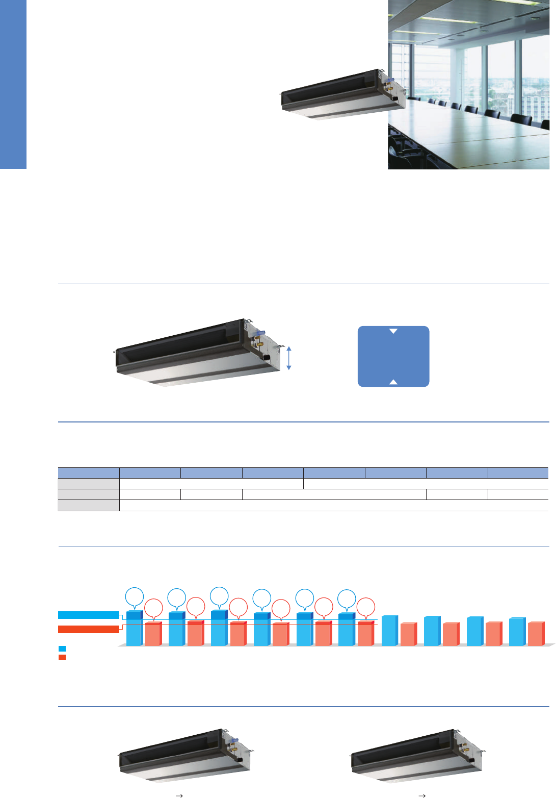
71
Inverter Heat Pump
Source
kW 7.1
3.3 - 8.1
1.89
–
–
7.1
396
6.3
A
++
7.6
3.5 - 10.2
2.21
–
–
4.7
4.7 (–10°C)
4.7 (–10°C)
3.5 (–20°C)
0
1666
4.0
A
+
19.4
0.06
0.4
46
20 - 22 - 24
40 - 42 - 44
60
943 - 950 - 330 (+30)
67
55.0
55.0
47
48
67
19.0
25
9.52 / 15.88
50
30
–15 ~ +46
–20 ~ +21
9.5
4.9 - 11.4
2.50
–
–
9.5
595
5.6
A
+
11.2
4.5 - 14.0
3.08
–
–
7.8
7.8 (–10°C)
7.8 (–10°C)
5.8 (–20°C)
0
2761
4.0
A
+
27.2
0.11
0.71
46
25 - 28 - 30
45 - 49 - 51
65
116
110.0
110.0
49
51
69
26.5
32
9.52 / 15.88
75
30
–15 ~ +46
–20 ~ +21
9.5
4.9 - 11.4
2.50
–
–
9.5
606
5.5
A
11.2
4.5 - 14.0
3.08
–
–
7.8
7.8 (–10°C)
7.8 (–10°C)
5.8 (–20°C)
0
2761
4.0
A
+
8.7
0.11
0.71
46
25 - 28 - 30
45 - 49 - 51
65
123
110.0
110.0
49
51
69
8.0
16
9.52 / 15.88
75
30
–15 ~ +46
–20 ~ +21
12.5
5.5 - 14.0
4.09
3.06
–
12.5
847
5.0
*
4
–
14.0
5.0 - 16.0
4.24
3.30
–
9.3
9.3 (–10°C)
9.3 (–10°C)
7.0 (–20°C)
0
3285
4.0
*
4
–
27.2
0.11
0.73
1900 - 600 - 360
46
25 - 28 - 31
45 - 49 - 51
66
116
120.0
120.0
50
52
70
26.5
32
9.52 / 15.88
75
30
–15 ~ +46
–20 ~ +21
12.5
5.5 - 14.0
4.09
3.06
–
12.5
885
4.9
*
4
–
14.0
5.0 - 16.0
4.24
3.30
–
9.3
9.3 (–10°C)
9.3 (–10°C)
7.0 (–20°C)
0
3285
4.0
*
4
–
10.2
0.11
0.73
46
25 - 28 - 31
45 - 49 - 51
66
125
120.0
120.0
50
52
70
9.5
16
9.52 / 15.88
75
30
–15 ~ +46
–20 ~ +21
13.4
6.2 - 15.0
4.06
3.30
–
13.4
872
5.3
*
4
–
16.0
5.7 - 18.0
4.79
3.34
–
10.6
10.6 (–10°C)
10.6 (–10°C)
7.9 (–20°C)
0
3331
4.4
*
4
–
28.7
0.11
0.73
48
25 - 28 - 31
45 - 49 - 51
66
118
120.0
120.0
50
52
70
28.0
40
9.52 / 15.88
75
30
–15 ~ +46
–20 ~ +21
13.4
6.2 - 15.0
4.06
3.30
–
13.4
883
5.3
*
4
–
16.0
5.7 - 18.0
4.79
3.34
–
10.6
10.6 (–10°C)
10.6 (–10°C)
7.9 (–20°C)
0
3331
4.4
*
4
–
13.7
0.11
0.73
48
25 - 28 - 31
45 - 49 - 51
66
131
120.0
120.0
50
52
70
13.0
16
9.52 / 15.88
75
30
–15 ~ +46
–20 ~ +21
Outdoor power supply
VKA
•
VHA:230 / Single / 50, YKA:400 / Three / 50
R410A*
1
PSA-RP71KA
PUHZ-ZRP71VHA
PSA-RP100KA
PUHZ-ZRP100VKA2 PUHZ-ZRP100YKA2
PSA-RP125KA
PUHZ-ZRP125VKA2 PUHZ-ZRP125YKA2
PSA-RP140KA
PUHZ-ZRP140VKA2 PUHZ-ZRP140YKA2
Type
Outdoor (V/Phase/Hz)
Power
Supply
Capacity
Total Input
Rated
Cooling
Heating
(Average
Season)
Operating Current (max)
Indoor
Unit
Outdoor
Unit
Indoor Unit
Outdoor Unit
Refrigerant
kW
Min - Max
kW
kW
kWh/a
Rated
Rated
EEL Rank
EER
Design Load
kW
Min - Max
kW
Rated
kW
kW
A
Capacity
Total Input
COP
Design Load
kW
kW
kW
kW
kWh/a
kW
Declared Capacity
Back Up Heating Capacity
Annual Electricity Consumption
*
2
SCOP
Input Rated
A
Operating Current (max)
mm
Dimensions <Panel>
kg
Weight <Panel>
kg
Weight
m
3
/min
Air Volume [Lo-Mid-Hi]
dB(A)
Sound Level (SPL) [Lo-Mid-Hi]
dB(A)
Sound Level (PWL)
H × W × D
mm
Dimensions H × W × D
Ext.
Piping
mm
Diameter Liquid / Gas
Guaranteed Operating Range
[Outdoor]
°C
Cooling
*
3
°C
Heating
m
Max. Length Out-In
m
Max. Height Out-In
m
3
/min
Air Volume Cooling
m
3
/min
Heating
dB(A)
dB(A)
dB(A)
Sound Level (SPL)
Cooling
Sound Level (PWL)
Cooling
A
Operating Current (max)
A
Breaker Size
Heating
EEL Rank
at reference design temperature
at bivalent temperature
at operation limit temperature
Energy Efficiency Class
Energy Efficiency Class
SEER
Annual Electricity Consumption
*
2
*1 Refrigerant leakage contributes to climate change. Refrigerant with lower global warming potential (GWP) would contribute less to global warming than a refrigerant with higher GWP, if leaked to the atmosphere. This appliance
contains a refrigerant fluid with a GWP equal to 1975. This means that if 1kg of this refrigerant fluid would be leaked to the atmosphere, the impact on global warming would be 1975 times higher than 1kg of CO2, over a period
of 100 years. Never try to interfere with the refrigerant circuit yourself or disassemble the product yourself and always ask a professional.
*2 Energy consumption based on standard test results. Actual energy consumption will depend on how the appliance is used and where it is located.
*3 Optional air protection guide is required where ambient temperature is lower than –5°C. *4 SEER/SCOP values are measured based on EN14825. These values are reference purpose only.
Inverter Heat Pump
Source
kW 9.4
4.9 - 11.2
3.120
–
–
9.4
716
4.6
B
11.2
4.5 - 12.5
3.280
–
–
8.0
6.3 (–10°C)
7.1 (–7°C)
5.0 (–15°C)
1.7
2945
3.8
A
28.7
0.11
0.71
46
25 - 28 - 30
45 - 49 - 51
65
75
60.0
60.0
50
54
70
28.0
32
9.52 / 15.88
50
30
–15 ~ +46
–15 ~ +21
9.4
4.9 - 11.2
3.120
–
–
9.4
716
4.6
B
11.2
4.5 - 12.5
3.280
–
–
8.0
6.3 (–10°C)
7.1 (–7°C)
5.0 (–15°C)
1.7
2945
3.8
A
13.7
0.11
0.71
46
25 - 28 - 30
45 - 49 - 51
65
77
60.0
60.0
50
54
70
13.0
16
9.52 / 15.88
50
30
–15 ~ +46
–15 ~ +21
943 - 950 - 330 (+30) 1350-950 - 330 (+30)
12.3
5.5 - 14.0
4.380
2.81
C
–
–
–
–
14.0
5.0 - 16.0
4.980
2.81
D
–
–
–
–
–
–
–
–
28.7
0.11
0.73
46
25 - 28 - 31
45 - 49 - 51
66
99
100.0
100.0
51
55
71
28.0
32
9.52 / 15.88
50
30
–15 ~ +46
–15 ~ +21
12.3
5.5 - 14.0
4.380
2.81
C
–
–
–
–
14.0
5.0 - 16.0
4.980
2.81
D
–
–
–
–
–
–
–
–
13.7
0.11
0.73
46
25 - 28 - 31
45 - 49 - 51
66
101
100.0
100.0
51
55
71
13.0
16
9.52 / 15.88
50
30
–15 ~ +46
–15 ~ +21
13.6
5.5 - 15.0
5.640
2.41
E
–
–
–
–
16.0
5.0 - 18.0
5.690
2.81
D
–
–
–
–
–
–
–
–
30.2
0.11
0.73
48
25 - 28 - 31
45 - 49 - 51
66
99
100.0
100.0
52
56
73
29.5
40
9.52 / 15.88
50
30
–15 ~ +46
–15 ~ +21
13.6
5.5 - 15.0
5.640
2.41
E
–
–
–
–
16.0
5.0 - 18.0
5.690
2.81
D
–
–
–
–
–
–
–
–
13.7
0.11
0.73
48
25 - 28 - 31
45 - 49 - 51
66
101
100.0
100.0
52
56
73
13.0
16
9.52 / 15.88
50
30
–15 ~ +46
–15 ~ +21
Outdoor power supply
VHA3
•
VHA4:230 / Single / 50, YHA
•
YHA2:400 / Three / 50
R410A*
1
PSA-RP100KA PSA-RP100KA PSA-RP125KA PSA-RP125KA PSA-RP140KA PSA-RP140KA
PUHZ-P100VHA4 PUHZ-P100YHA2 PUHZ-P125VHA3 PUHZ-P125YHAPUHZ-P140VHA3 PUHZ-P140YHA
Type
Outdoor (V/Phase/Hz)
Power
Supply
Capacity
Total Input
Rated
Cooling
Heating
(Average
Season)
Operating Current (max)
Indoor
Unit
Outdoor
Unit
Indoor Unit
Outdoor Unit
Refrigerant
kW
Min - Max
kW
kW
kWh/a
Rated
Rated
EEL Rank
EER
Design Load
kW
Min - Max
kW
Rated
kW
kW
A
Capacity
Total Input
COP
Design Load
kW
kW
kW
kW
kWh/a
kW
Declared Capacity
Back Up Heating Capacity
Annual Electricity Consumption
*
2
SCOP
Input Rated
A
Operating Current (max)
mm
Dimensions <Panel>
kg
Weight <Panel>
kg
Weight
m
3
/min
Air Volume [Lo-Mid-Hi]
dB(A)
Sound Level (SPL) [Lo-Mid-Hi]
dB(A)
Sound Level (PWL)
H × W × D
mm
Dimensions H × W × D
Ext.
Piping
mm
Diameter Liquid / Gas
Guaranteed Operating Range
[Outdoor]
°C
Cooling
*
3
°C
Heating
m
Max. Length Out-In
m
Max. Height Out-In
m
3
/min
Air Volume Cooling
m
3
/min
Heating
dB(A)
dB(A)
dB(A)
Sound Level (SPL)
Cooling
Sound Level (PWL)
Cooling
A
Operating Current (max)
A
Breaker Size
Heating
EEL Rank
at reference design temperature
at bivalent temperature
at operation limit temperature
Energy Efficiency Class
Energy Efficiency Class
SEER
Annual Electricity Consumption
*
2
*1 Refrigerant leakage contributes to climate change. Refrigerant with lower global warming potential (GWP) would contribute less to global warming than a refrigerant with higher GWP, if leaked to the atmosphere. This appliance
contains a refrigerant fluid with a GWP equal to 1975. This means that if 1kg of this refrigerant fluid would be leaked to the atmosphere, the impact on global warming would be 1975 times higher than 1kg of CO2, over a period
of 100 years. Never try to interfere with the refrigerant circuit yourself or disassemble the product yourself and always ask a professional.
*2 Energy consumption based on standard test results. Actual energy consumption will depend on how the appliance is used and where it is located.
*3 Optional air protection guide is required where ambient temperature is lower than –5°C. *4 SEER/SCOP values are measured based on EN14825. These values are reference purpose only.
1338-1050-330(+40)
1900 - 600 - 360
Optional
71-140V
Optional
Optional
Optional Optional
Wi-Fi
Interface
Optional
Optional
Optional Optional
PEAD
SERIES
The thin, ceiling-concealed indoor units of this series are the perfect answer for the air
conditioning needs of buildings with minimum ceiling installation space and wide-
ranging external static pressure. Energy-saving efficiency has been improved, reduc-
ing electricity consumption and contributing to a further reduction in operating cost.
Compact Indoor Units
The height of the models from 35–140 has been unified to 250mm. Compared to the previous PEAD-RP EA model, the height has been reduced
by as much as 75mm (models 100–140), making installation in low ceilings with minimal clearance space possible.
External Static Pressure
■ External static pressure setting
Series
PEAD-RP EA
PEAD-RP GA
PEAD-RP JA
35 50 60 71 100125 140
30/70Pa70/130 (with optional motor) Pa
10/50/70Pa
––
––
35/50/70/100/150Pa
External static pressure conversion can be set up to five stages. Capable of being set to a maximum of 150Pa, units are applicable to a wide range
of building types.
Drain Pump Option Available with All Models
The line-up consists of two types, models with or without a built-in drain pump.
PEAD-RP35/50/60/71/100/125/140JA(L)Q
Reduction of
75mm
(models 100 –140)
compared to PEAD-EA
PEAD-RP JA(L)Q
250mm
PEAD-RP JAQ Drain pump built-in PEAD-RP JALQ No drain pump
✽
Units with an “L” included at the end of the model name are not equipped with a drain pump.
✽
For products with capacity over 10.0kW, SEER/SCOP values are measured based on EN14825. These values are for reference purposes only.
ErP Lot 10-compliant, Achieving High Energy Efficiency of SEER/SCOP Rank A
+
and A
++
A direct-current (DC) fan motor is installed in the indoor unit, increasing the seasonal energy efficiency of the newly designed Power Inverter Series
(PUHZ-ZRP) and resulting in compliance of the full-capacity models with ErP Lot 10 and energy rankings of A
+
/A
++
for cooling and A/A
+
for heating.
This contributes to an impressive reduction in the cost of annual electricity.
PEAD-RP35JALQ
PUHZ-ZRP35VKA
PEAD-RP50JALQ
PUHZ-ZRP50VKA
PEAD-RP60JALQ
PUHZ-ZRP60VHA
PEAD-RP71JALQ
PUHZ-ZRP71VHA
PEAD-RP100JALQ
PUHZ-ZRP100VKA2
PEAD-RP100JALQ
PUHZ-ZRP100YKA2
PEAD-RP125JALQ
PUHZ-ZRP125VKA2
PEAD-RP125JALQ
PUHZ-ZRP125YKA2
PEAD-RP140JALQ
PUHZ-ZRP140VKA2
PEAD-RP140JALQ
PUHZ-ZRP140YKA2
Cooling
Heating
6.0
4.0
SEER
A
+
SCOP
A
+
5.8
4.3
SEER
A
+
SCOP
A
+
6.1
4.1
SEER
A
++
SCOP
A
+
5.7
3.9
SEER
A
+
SCOP
A
5.7
4.2
SEER
A
+
SCOP
A
+
5.6
4.2
SEER
A
+
SCOP
A
+
5.1
3.9
5.0
3.9
4.9
4.0
4.8
4.0
Wi-Fi
Interface
Minimum SCOP 3.8
Minimum SEER 4.6
Optional
POWER INVERTER
PSZ-RP SERIES
STANDARD INVERTER
PSZ-P SERIES
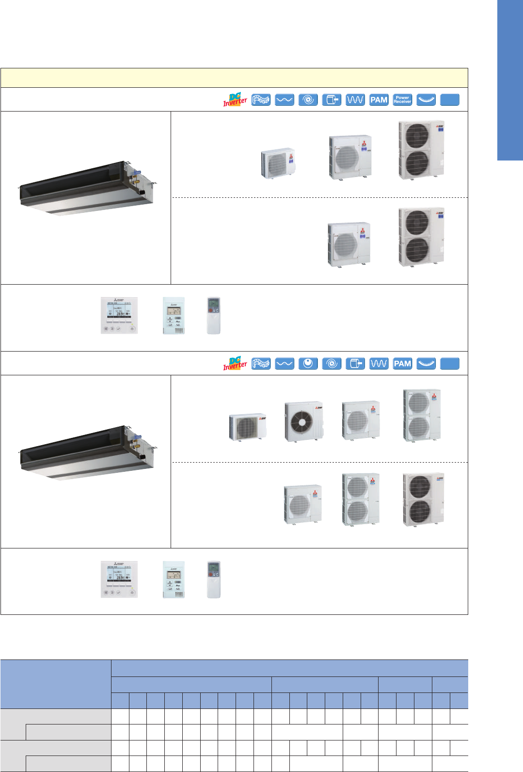
72
PEAD-RP JA Indoor Unit Combinations
Indoor unit combinations shown below are possible.
Indoor Unit Combination
Power Inverter (PUHZ-ZRP)
Distribution Pipe
Standard Inverter (PUHZ-P&SUZ)
Distribution Pipe
For Single
35
35x1
–
35x1
–
50x1
–
50x1
–
60x1
–
60x1
–
71x1
–
71x1
–
100x1
–
100x1
–
125x1
–
125x1
–
140x1
–
140x1
–
–
–
–
–
–
–
–
–
35x2
–
–
50x2
50x2
60x2
60x2
71x2
MSDD-50TR-E
71x2
MSDD-50TR-E
100x2
100x2
MSDD-50WR-E
125x2
MSDD-50WR-E
MSDF-1111R-E
MSDF-1111R-E
125x2
50x3
50x3
60x3
60x3
50x4
50x4
71x3
MSDT-111R-E
71x3
MSDT-111R-E
60x4
60x4
For Twin For Tr iple
For Quadruple
Outdoor Unit Capacity
50 60 71 100 125 140 200 250 71 100 125 140 200 250 140 200 250 200 250
PUHZ-P125/140SUZ-KA50/60/71 PUHZ-P100SUZ-KA35
PUHZ-P200/250
PUHZ-ZRP100/125/140PUHZ-ZRP60/71
PUHZ-ZRP100/125/140/200/250
PUHZ-ZRP71
PEAD-RP35/50/60/71/100/125/140
PUHZ-ZRP35/50
PEAD-RP35/50/60/71/100/125/140
Joint Lap
35-71
Vector Sine Wave
35-140
Grooved Piping
Vector-Wave
100-250
DC Scroll
Joint Lap
35-71
Vector Sine Wave
100-250
DC Rotary
71-140
35-140
Grooved Piping
100-250
Vector-Wave
DC Fan Motor
200/250
DC Scroll
PUHZ-P125/140PUHZ-P100
Optional
JAQ
60-140V/200/250 PUHZ
OptionalOptional
Optional
OptionalOptional
Optional
PUHZ
PUHZ
PUHZ PUHZ
Optional
OptionalOptional
PUHZ PUHZSUZ
Optional
PUHZ
JAQ
OptionalOptional
POWER INVERTER
PEDZ-RP JA SERIES
Please fill out the requested information
Please fill out the requested information
STANDARD INVERTER
PEDZ-P JA SERIES
Please fill out the requested information
Please fill out the requested information
SERIES SELECTION
Indoor Unit Outdoor Unit
Remote Controller
Power Inverter Series
Indoor Unit
Remote Controller
Standard Inverter Series
Outdoor Unit
For Single
For Multi (Twin/Triple/Quadruple)
Optional Optional
Optional Optional
Optional
Optional
For Single
For Multi
(Twin/Triple/Quadruple)
Inverter Heat Pump
Source
kW
Outdoor power supply
VA5
•
VHA3
•
VHA4:230 / Single / 50, YHA
•
YHA2:400 / Three / 50
R410A*
1
PEAD-
RP35JA(L)Q
PEAD-
RP50JA(L)Q
PEAD-
RP60JA(L)Q
PEAD-RP100JA(L)Q PEAD-RP125JA(L)Q PEAD-RP140JA(L)Q
PEAD-
RP71JA(L)Q
SUZ-KA35VA5 SUZ-KA50VA5 SUZ-KA60VA5 SUZ-KA71VA5
PUHZ-
P100VHA4
PUHZ-
P100YHA2
PUHZ-
P125VHA3
PUHZ-
P125YHA
PUHZ-
P140VHA3
PUHZ-
P140YHA
Type
Outdoor (V/Phase/Hz)
943-950-330(+30) 1350-950-330(+30)
Power
Supply
Capacity
Total Input
Rated
Cooling
Heating
(Average
Season)
Operating Current (max)
Indoor
Unit
Outdoor
Unit
Indoor Unit
Outdoor Unit
Refrigerant
kW
Min - Max
kW
kW
kWh/a
Rated
Rated
EEL Rank
EER
*
4
Design Load
kW
Min - Max
kW
Rated
kW
kW
A
Capacity
Total Input
COP
*
4
Design Load
kW
kW
kW
kW
kWh/a
kW
Declared Capacity
Back Up Heating Capacity
Annual Electricity Consumption
*
2
SCOP
*
4
Input [Cooling / Heating] Rated
A
Operating Current (max)
mm
Dimensions <Panel>
kg
Weight <Panel>
kg
Weight
m
3
/min
Air Volume [Lo-Mid-Hi]
dB(A)
Sound Level (SPL) [Lo-Mid-Hi]
Pa
External Static Pressure
dB(A)
Sound Level (PWL)
H × W × D
mm
Dimensions H × W × D
Ext.
Piping
mm
Diameter Liquid / Gas
Guaranteed Operating Range
[Outdoor]
°C
Cooling
°C
Heating
m
Max. Length Out-In
m
Max. Height Out-In
m
3
/min
Air Volume Cooling
m
3
/min
Heating
dB(A)
dB(A)
dB(A)
Sound Level (SPL)
Cooling
Sound Level (PWL)
Cooling
A
Operating Current (max)
A
Breaker Size
Heating
EEL Rank
at reference design temperature
at bivalent temperature
at operation limit temperature
Energy Efficiency Class
Energy Efficiency Class
SEER
*
4
Annual Electricity Consumption
*
2
35 / 50 / 70 / 100 / 150
*1 Refrigerant leakage contributes to climate change. Refrigerant with lower global warming potential (GWP) would contribute less to global warming than a refrigerant with higher GWP, if leaked to the atmosphere. This appliance
contains a refrigerant fluid with a GWP equal to 1975. This means that if 1kg of this refrigerant fluid would be leaked to the atmosphere, the impact on global warming would be 1975 times higher than 1kg of CO
2
, over a period
of 100 years. Never try to interfere with the refrigerant circuit yourself or disassemble the product yourself and always ask a professional.
*2 Energy consumption based on standard test results. Actual energy consumption will depend on how the appliance is used and where it is located.
*3 Optional air protection guide is required where ambient temperature is lower than –5°C. *4 EER/COP and SEER/SCOP for RP35~71 are measured at ESP 35Pa, for RP100 at ESP 37Pa, for RP125/140 at ESP 50Pa.
3.6
1.4 - 3.9
1.050 (1.030)
–
–
3.6
229 (213)
5.5 (5.9)
A (A
+
)
4.1
1.7 - 5.0
1.110
–
–
2.8
2.5 (–10°C)
2.5 (–7°C)
2.5 (–10°C)
0.3
980
4.0
A
+
9.3
0.09(0.07) / 0.07
1.07
26 (25)
10.0 - 12.0 - 14.0
23 - 27 - 30
52
550 - 800 - 285
35
36.3
34.8
49
50
62
8.2
16
6.35 / 9.52
20
12
–10 ~ +46
–10 ~ +24
4.9
2.3 - 5.6
1.480 (1.460)
–
–
4.9
318 (301)
5.4 (5.7)
A (A
+
)
5.9
1.7 - 7.2
1.620
–
–
4.4
3.9 (–10°C)
3.9 (–7°C)
3.9 (–10°C)
0.5
1466
4.2
A
+
13.4
0.11(0.09)/0.09
1.39
28 (27)
12.0-14.5-17.0
26 - 31 - 35
57
54
44.6
44.6
52
52
65
12.0
20
6.35 / 12.7
30
30
–15 ~ +46
–10 ~ +24
250 - 900 - 732
250-1100-732 250-1400-732 250-1600-732
5.7
2.3 - 6.3
1.670 (1.650)
–
–
5.7
351 (335)
5.6 (5.9)
A
+
(A
+
)
7.0
2.5 - 8.0
1.930
–
–
4.5
4.1 (–10°C)
4.1 (–7°C)
4.1 (–10°C)
0.5
1569
4.0
A
+
15.6
0.12(0.10) /0.10
1.62
33 (32)
14.5 -18.0-21.0
25 - 29 - 33
55
880-840-330
50
40.9
49.2
55
55
65
14.0
20
6.35 / 15.88
30
30
–15 ~ +46
–10 ~ +24
7.1
2.8 - 8.1
2.080 (2.060)
–
–
7.1
429 (413)
5.8 (6.0)
A
+
(A
+
)
8.0
2.6 - 10.2
2.040
–
–
6.0
5.3 (–10°C)
5.3 (–7°C)
5.3 (–10°C)
0.7
2153
3.9
A
18.1
0.17(0.15) / 0.15
1.97
33 (32)
17.5-21.0-25.0
26 - 30 - 34
58
53
50.1
48.2
55
55
69
16.1
20
9.52 / 15.88
30
30
–15 ~ +46
–10 ~ +24
9.4
4.9 - 11.2
3.120(3.102)
–
–
9.4
716(694)
4.6(4.7)
B
11.2
4.5 - 12.5
3.103
–
–
8.0
6.3 (–10°C)
7.1 (–7°C)
5.0 (–15°C)
1.7
2945
3.8
A
30.7
0.25(0.23)/0.23
2.65
41 (40)
24.0-29.0-34.0
29 - 34 - 38
61
75
60.0
60.0
50
54
70
28.0
32
9.52 / 15.88
50
30
–15 ~ +46
*
3
–15 ~ +21
9.4
4.9 - 11.2
3.120(3.102)
–
–
9.
4
716(694)
4.6(4.7)
B
11.2
4.5 - 12.5
3.103
–
–
8.0
6.3 (–10°C)
7.1 (–7°C)
5.0 (–15°C)
1.7
2945
3.8
A
15.7
0.25(0.23)/0.23
2.65
41 (40)
24.0-29.0-34.0
29 - 34 - 38
61
77
60.0
60.0
50
54
70
13.0
16
9.52 / 15.88
50
30
–15 ~ +46
*
3
–15 ~ +21
12.3
5.5 - 14.0
4.220(4.200)
2.91 (2.93)
C
–
–
–
–
14.0
5.0 - 16.0
3.870
3.62
A
–
–
–
–
–
–
–
–
30.8
0.36(0.34)/0.34
2.76
43 (42)
29.5-35.5-42.0
33 - 36 - 40
65
99
100.0
100.0
51
55
71
28.0
32
9.52 / 15.88
50
30
–15 ~ +46
*
3
–15 ~ +21
12.3
5.5 - 14.0
4.220(4.200)
2.91 (2.93)
C
–
–
–
–
14.0
5.0 - 16.0
3.870
3.62
A
–
–
–
–
–
–
–
–
15.8
0.36(0.34)/0.34
2.76
43 (42)
29.5-35.5-42.0
33 - 36 - 40
65
101
100.0
100.0
51
55
71
13.0
16
9.52 / 15.88
50
30
–15 ~ +46
*
3
–15 ~ +21
13.6
5.5 - 15.0
4.520(4.500)
3.01 (3.02)
B
–
–
–
–
16.0
5.0 - 18.0
4.430
3.61
A
–
–
–
–
–
–
–
–
32.3
0.39(0.37)/0.37
2.78
47 (46)
32.0-39.0-46.0
34 - 38 - 43
66
99
100.0
100.0
52
56
73
29.5
40
9.52 / 15.88
50
30
–15 ~ +46
*
3
–15 ~ +21
13.6
5.5 - 15.0
4.520(4.500)
3.01 (3.02)
B
–
–
–
–
16.0
5.0 - 18.0
4.430
3.61
A
–
–
–
–
–
–
–
–
15.8
0.39(0.37)/0.37
2.78
47 (46)
32.0-39.0-46.0
34 - 38 - 43
66
101
100.0
100.0
52
56
73
13.0
16
9.52 / 15.88
50
30
–15 ~ +46
*
3
–15 ~ +21
Inverter Heat Pump
Source
kW
Outdoor power supply
VKA
•
VHA:230 / Single / 50, YKA:400 / Three / 50
R410A*
1
PEAD-
RP35JA(L)Q
PEAD-
RP50JA(L)Q
PEAD-
RP60JA(L)Q
PEAD-RP100JA(L)Q PEAD-RP125JA(L)Q PEAD-RP140JA(L)Q
PEAD-
RP71JA(L)Q
PUHZ-
ZRP35VKA
PUHZ-
ZRP50VKA
PUHZ-
ZRP60VHA
PUHZ-
ZRP71VHA
PUHZ-
ZRP100VKA2
PUHZ-
ZRP100YKA2
PUHZ-
ZRP125VKA2
PUHZ-
ZRP125YKA2
PUHZ-
ZRP140VKA2
PUHZ-
ZRP140YKA2
Type
Outdoor (V/Phase/Hz)
Power
Supply
Capacity
Total Input
Rated
Cooling
Heating
(Average
Season)
Operating Current (max)
Indoor
Unit
Outdoor
Unit
Indoor Unit
Outdoor Unit
Refrigerant
kW
Min - Max
kW
kW
kWh/a
Rated
Rated
EEL Rank
EER
*
5
Design Load
kW
Min - Max
kW
Rated
kW
kW
A
Capacity
Total Input
COP
*
5
Design Load
kW
kW
kW
kW
kWh/a
kW
Declared Capacity
Back Up Heating Capacity
Annual Electricity Consumption
*
2
SCOP
*
5
A
Operating Current (max)
mm
Dimensions <Panel>
kg
Weight <Panel>
kg
Weight
m
3
/min
Air Volume [Lo-Mid-Hi]
dB(A)
Sound Level (SPL) [Lo-Mid-Hi]
Pa
External Static Pressure
dB(A)
Sound Level (PWL)
H × W × D
mm
Dimensions H × W × D
Ext.
Piping
mm
Diameter Liquid / Gas
Guaranteed Operating Range
[Outdoor]
°C
Cooling
*
3
°C
Heating
m
Max. Length Out-In
m
Max. Height Out-In
m
3
/min
Air Volume Cooling
m
3
/min
Heating
dB(A)
dB(A)
dB(A)
Sound Level (SPL)
Cooling
Sound Level (PWL)
Cooling
A
Operating Current (max)
A
Breaker Size
Heating
EEL Rank
at reference design temperature
at bivalent temperature
at operation limit temperature
Energy Efficiency Class
Energy Efficiency Class
SEER
*
5
Annual Electricity Consumption
*
2
630 - 809 - 300 943 - 950 - 330(+30) 1338 - 1050 - 330(+40)
35 / 50 / 70 / 100 / 150
*1 Refrigerant leakage contributes to climate change. Refrigerant with lower global warming potential (GWP) would contribute less to global warming than a refrigerant with higher GWP, if leaked to the atmosphere. This appliance
contains a refrigerant fluid with a GWP equal to 1975. This means that if 1kg of this refrigerant fluid would be leaked to the atmosphere, the impact on global warming would be 1975 times higher than 1kg of CO
2
, over a period
of 100 years. Never try to interfere with the refrigerant circuit yourself or disassemble the product yourself and always ask a professional.
*2 Energy consumption based on standard test results. Actual energy consumption will depend on how the appliance is used and where it is located.
*3 Optional air protection guide is required where ambient temperature is lower than –5°C. *4 SEER/SCOP values are measured based on EN14825. These values are reference purpose only.
*5 EER/COP and SEER/SCOP for RP35~71 are measured at ESP 35Pa, for RP100 at ESP 37Pa, for RP125/140 at ESP 50Pa.
3.6
1.6 - 4.5
0.89 (0.87)
–
–
3.6
228 (211)
5.6(6.0)
A
+
(A
+
)
4.1
1.6 - 5.2
0.95
–
–
2.4
2.4(–10°C)
2.4(–10°C)
2.2(–11°C)
0
839
4.0
A
+
14.1
0.09 (0.07) / 0.07
1.07
26 (25)
10.0-12.0-14.0
23 - 27 - 30
52
43
45.0
45.0
44
46
65
13.0
16
6.35 / 12.7
50
30
–15 ~ +46
–11 ~ +21
5.0
2.3 - 5.6
1.44 (1.42)
–
–
5.0
317 (301)
5.5(5.8)
A(A
+
)
6.0
2.5 - 7.3
1.50
–
–
3.8
3.8 (–10°C)
3.8 (–10°C)
3.7 (–11°C)
0
1231
4.3
A
+
14.4
0.11(0.09) / 0.09
1.39
28 (27)
12.0-14.5-17.0
26 - 31 - 35
57
46
45.0
45.0
44
46
65
13.0
16
6.35 / 12.7
50
30
–15 ~ +46
–11 ~ +21
6.1
2.7 - 6.7
1.65 (1.63)
–
–
6.1
366(351)
5.8(6.1)
A
+
(A
++
)
7.0
2.8 - 8.2
1.79
–
–
4.4
4.4(–10°C)
4.4(–10°C)
2.8(–20°C)
0
1513
4.1
A
+
20.6
0.12 (0.10)/0.10
1.62
33 (32)
14.5-18.0-21.0
25 - 29 - 33
55
67
55.0
55.0
47
48
67
19.0
25
9.52 / 15.88
50
30
–15 ~ +46
–20 ~ +21
7.1
3.3 - 8.1
2.01 (1.99)
–
–
7.1
446(428)
5.6(5.7)
A
+
(A
+
)
8.0
3.5 - 10.2
2.03
–
–
4.9
4.9(–10°C)
4.9(–10°C)
3.7(–20°C)
0
1762
3.9
A
21.0
0.17 (0.15)/0.15
1.97
33 (32)
17.5-21.0-25.0
26 - 30 - 34
58
67
55.0
55.0
47
48
67
19.0
25
9.52 / 15.88
50
30
–15 ~ +46
–20 ~ +21
9.5
4.9 - 11.4
2.43 (2.41)
–
–
9.5
593(583)
5.6(5.7)
A
+
(A
+
)
11.2
4.5 - 14.0
2.60
–
–
7.8
7.8(–10°C)
7.8(–10°C)
5.8(–20°C)
0
2627
4.2
A
+
29.2
0.25 (0.23)/0.23
2.65
41 (40)
24.0-29.0-34.0
29 - 34 - 38
61
116
110.0
110.0
49
51
69
26.5
32
9.52 / 15.88
75
30
–15 ~ +46
–20 ~ +21
9.5
4.9 - 11.4
2.43 (2.41)
–
–
9.5
602(592)
5.5(5.6)
A(A
+
)
11.2
4.5 - 14.0
2.60
–
–
7.8
7.8(–10°C)
7.8(–10°C)
5.8(–20°C)
0
2627
4.2
A
+
10.7
0.25 (0.23)/0.23
2.65
41 (40)
24.0-29.0-34.0
29 - 34 - 38
61
123
110.0
110.0
49
51
69
8.0
16
9.52 / 15.88
75
30
–15 ~ +46
–20 ~ +21
12.5
5.5 - 14.0
3.86 (3.83)
3.24 (3.26)
–
12.5
875(858)
5.0(5.1)
*
4
–
14.0
5.0 - 16.0
3.51
3.99
–
9.3
9.3(–10°C)
9.3(–10°C)
7.0(–20°C)
0
3370
3.9
*
4
–
29.3
0.36 (0.34)/0.34
2.76
43 (42)
29.5-35.5-42.0
33 - 36 - 40
65
116
120.0
120.0
50
52
70
26.5
32
9.52 / 15.88
75
30
–15 ~ +46
–20 ~ +21
12.5
5.5 - 14.0
3.86 (3.83)
3.24 (3.26)
–
12.5
886(873)
4.9(5.0)
*
4
–
14.0
5.0 - 16.0
3.51
3.99
–
9.3
9.3(–10°C)
9.3(–10°C)
7.0(–20°C)
0
3370
3.9
*
4
–
12.3
0.36 (0.34)/0.34
2.76
43 (42)
29.5-35.5-42.0
33 - 36 - 40
65
125
120.0
120.0
50
52
70
9.5
16
9.52 / 15.88
75
30
–15 ~ +46
–20 ~ +21
13.4
6.2 - 15.3
4.32 (4.29)
3.10 (3.12)
–
13.4
980(956)
4.8(4.9)
*
4
–
16.0
5.7 - 18.0
4.07
3.93
–
10.6
10.6(–10°C)
10.6(–10°C)
7.9(–20°C)
0
3763
4.0
*
4
–
30.8
0.39 (0.37)/0.37
2.78
47 (46)
32.0-39.0-46.0
34 - 38 - 43
66
118
120.0
120.0
50
52
70
28.0
40
9.52 / 15.88
75
30
–15 ~ +46
–20 ~ +21
13.4
6.2 - 15.3
4.32 (4.29)
3.10 (3.12)
–
13.4
991(976)
4.7(4.8)
*
4
–
16.0
5.7 - 18.0
4.07
3.93
–
10.6
10.6 (–10°C)
10.6 (–10°C)
7.9(–20°C)
0
3763
4.0
*
4
–
15.8
0.39 (0.37)/0.37
2.78
47 (46)
32.0-39.0-46.0
34 - 38 - 43
66
131
120.0
120.0
50
52
70
13.0
16
9.52 / 15.88
75
30
–15 ~ +46
–20 ~ +21
RatedInput [Cooling / Heating]
35-71
Heat Caulking
Fixing Method
35-71
Heat Caulking
Fixing Method
DC Fan Motor
250 -900 - 732
250
-
1100
-
732 250
-
1400
-
732 250-1600-732
Wi-Fi
Interface
Wi-Fi
Interface
73
PEAD-RP JA Indoor Unit Combinations
Indoor unit combinations shown below are possible.
Indoor Unit Combination
Power Inverter (PUHZ-ZRP)
Distribution Pipe
Standard Inverter (PUHZ-P&SUZ)
Distribution Pipe
For Single
35
35x1
–
35x1
–
50x1
–
50x1
–
60x1
–
60x1
–
71x1
–
71x1
–
100x1
–
100x1
–
125x1
–
125x1
–
140x1
–
140x1
–
–
–
–
–
–
–
–
–
35x2
–
–
50x2
50x2
60x2
60x2
71x2
MSDD-50TR-E
71x2
MSDD-50TR-E
100x2
100x2
MSDD-50WR-E
125x2
MSDD-50WR-E
MSDF-1111R-E
MSDF-1111R-E
125x2
50x3
50x3
60x3
60x3
50x4
50x4
71x3
MSDT-111R-E
71x3
MSDT-111R-E
60x4
60x4
For Twin For Tr iple
For Quadruple
Outdoor Unit Capacity
50 60 71 100 125 140 200 250 71 100 125 140 200 250 140 200 250 200 250
PUHZ-P125/140SUZ-KA50/60/71 PUHZ-P100SUZ-KA35
PUHZ-P200/250
PUHZ-ZRP100/125/140PUHZ-ZRP60/71
PUHZ-ZRP100/125/140/200/250
PUHZ-ZRP71
PEAD-RP35/50/60/71/100/125/140
PUHZ-ZRP35/50
PEAD-RP35/50/60/71/100/125/140
Joint Lap
35-71
Vector Sine Wave
35-140
Grooved Piping
Vector-Wave
100-250
DC Scroll
Joint Lap
35-71
Vector Sine Wave
100-250
DC Rotary
71-140
35-140
Grooved Piping
100-250
Vector-Wave
DC Fan Motor
200/250
DC Scroll
PUHZ-P125/140PUHZ-P100
Optional
JAQ
60-140V/200/250 PUHZ
OptionalOptional
Optional
OptionalOptional
Optional
PUHZ
PUHZ
PUHZ PUHZ
Optional
OptionalOptional
PUHZ PUHZSUZ
Optional
PUHZ
JAQ
OptionalOptional
POWER INVERTER
PEDZ-RP JA SERIES
Please fill out the requested information
Please fill out the requested information
STANDARD INVERTER
PEDZ-P JA SERIES
Please fill out the requested information
Please fill out the requested information
SERIES SELECTION
Indoor Unit Outdoor Unit
Remote Controller
Power Inverter Series
Indoor Unit
Remote Controller
Standard Inverter Series
Outdoor Unit
For Single
For Multi (Twin/Triple/Quadruple)
Optional Optional
Optional Optional
Optional
Optional
For Single
For Multi
(Twin/Triple/Quadruple)
Inverter Heat Pump
Source
kW
Outdoor power supply
VA5
•
VHA3
•
VHA4:230 / Single / 50, YHA
•
YHA2:400 / Three / 50
R410A*
1
PEAD-
RP35JA(L)Q
PEAD-
RP50JA(L)Q
PEAD-
RP60JA(L)Q
PEAD-RP100JA(L)Q PEAD-RP125JA(L)Q PEAD-RP140JA(L)Q
PEAD-
RP71JA(L)Q
SUZ-KA35VA5 SUZ-KA50VA5 SUZ-KA60VA5 SUZ-KA71VA5
PUHZ-
P100VHA4
PUHZ-
P100YHA2
PUHZ-
P125VHA3
PUHZ-
P125YHA
PUHZ-
P140VHA3
PUHZ-
P140YHA
Type
Outdoor (V/Phase/Hz)
943-950-330(+30) 1350-950-330(+30)
Power
Supply
Capacity
Total Input
Rated
Cooling
Heating
(Average
Season)
Operating Current (max)
Indoor
Unit
Outdoor
Unit
Indoor Unit
Outdoor Unit
Refrigerant
kW
Min - Max
kW
kW
kWh/a
Rated
Rated
EEL Rank
EER
*
4
Design Load
kW
Min - Max
kW
Rated
kW
kW
A
Capacity
Total Input
COP
*
4
Design Load
kW
kW
kW
kW
kWh/a
kW
Declared Capacity
Back Up Heating Capacity
Annual Electricity Consumption
*
2
SCOP
*
4
Input [Cooling / Heating] Rated
A
Operating Current (max)
mm
Dimensions <Panel>
kg
Weight <Panel>
kg
Weight
m
3
/min
Air Volume [Lo-Mid-Hi]
dB(A)
Sound Level (SPL) [Lo-Mid-Hi]
Pa
External Static Pressure
dB(A)
Sound Level (PWL)
H × W × D
mm
Dimensions H × W × D
Ext.
Piping
mm
Diameter Liquid / Gas
Guaranteed Operating Range
[Outdoor]
°C
Cooling
°C
Heating
m
Max. Length Out-In
m
Max. Height Out-In
m
3
/min
Air Volume Cooling
m
3
/min
Heating
dB(A)
dB(A)
dB(A)
Sound Level (SPL)
Cooling
Sound Level (PWL)
Cooling
A
Operating Current (max)
A
Breaker Size
Heating
EEL Rank
at reference design temperature
at bivalent temperature
at operation limit temperature
Energy Efficiency Class
Energy Efficiency Class
SEER
*
4
Annual Electricity Consumption
*
2
35 / 50 / 70 / 100 / 150
*1 Refrigerant leakage contributes to climate change. Refrigerant with lower global warming potential (GWP) would contribute less to global warming than a refrigerant with higher GWP, if leaked to the atmosphere. This appliance
contains a refrigerant fluid with a GWP equal to 1975. This means that if 1kg of this refrigerant fluid would be leaked to the atmosphere, the impact on global warming would be 1975 times higher than 1kg of CO
2
, over a period
of 100 years. Never try to interfere with the refrigerant circuit yourself or disassemble the product yourself and always ask a professional.
*2 Energy consumption based on standard test results. Actual energy consumption will depend on how the appliance is used and where it is located.
*3 Optional air protection guide is required where ambient temperature is lower than –5°C. *4 EER/COP and SEER/SCOP for RP35~71 are measured at ESP 35Pa, for RP100 at ESP 37Pa, for RP125/140 at ESP 50Pa.
3.6
1.4 - 3.9
1.050 (1.030)
–
–
3.6
229 (213)
5.5 (5.9)
A (A
+
)
4.1
1.7 - 5.0
1.110
–
–
2.8
2.5 (–10°C)
2.5 (–7°C)
2.5 (–10°C)
0.3
980
4.0
A
+
9.3
0.09(0.07) / 0.07
1.07
26 (25)
10.0 - 12.0 - 14.0
23 - 27 - 30
52
550 - 800 - 285
35
36.3
34.8
49
50
62
8.2
16
6.35 / 9.52
20
12
–10 ~ +46
–10 ~ +24
4.9
2.3 - 5.6
1.480 (1.460)
–
–
4.9
318 (301)
5.4 (5.7)
A (A
+
)
5.9
1.7 - 7.2
1.620
–
–
4.4
3.9 (–10°C)
3.9 (–7°C)
3.9 (–10°C)
0.5
1466
4.2
A
+
13.4
0.11(0.09)/0.09
1.39
28 (27)
12.0-14.5-17.0
26 - 31 - 35
57
54
44.6
44.6
52
52
65
12.0
20
6.35 / 12.7
30
30
–15 ~ +46
–10 ~ +24
250 - 900 - 732
250-1100-732 250-1400-732 250-1600-732
5.7
2.3 - 6.3
1.670 (1.650)
–
–
5.7
351 (335)
5.6 (5.9)
A
+
(A
+
)
7.0
2.5 - 8.0
1.930
–
–
4.5
4.1 (–10°C)
4.1 (–7°C)
4.1 (–10°C)
0.5
1569
4.0
A
+
15.6
0.12(0.10) /0.10
1.62
33 (32)
14.5 -18.0-21.0
25 - 29 - 33
55
880-840-330
50
40.9
49.2
55
55
65
14.0
20
6.35 / 15.88
30
30
–15 ~ +46
–10 ~ +24
7.1
2.8 - 8.1
2.080 (2.060)
–
–
7.1
429 (413)
5.8 (6.0)
A
+
(A
+
)
8.0
2.6 - 10.2
2.040
–
–
6.0
5.3 (–10°C)
5.3 (–7°C)
5.3 (–10°C)
0.7
2153
3.9
A
18.1
0.17(0.15) / 0.15
1.97
33 (32)
17.5-21.0-25.0
26 - 30 - 34
58
53
50.1
48.2
55
55
69
16.1
20
9.52 / 15.88
30
30
–15 ~ +46
–10 ~ +24
9.4
4.9 - 11.2
3.120(3.102)
–
–
9.4
716(694)
4.6(4.7)
B
11.2
4.5 - 12.5
3.103
–
–
8.0
6.3 (–10°C)
7.1 (–7°C)
5.0 (–15°C)
1.7
2945
3.8
A
30.7
0.25(0.23)/0.23
2.65
41 (40)
24.0-29.0-34.0
29 - 34 - 38
61
75
60.0
60.0
50
54
70
28.0
32
9.52 / 15.88
50
30
–15 ~ +46
*
3
–15 ~ +21
9.4
4.9 - 11.2
3.120(3.102)
–
–
9.
4
716(694)
4.6(4.7)
B
11.2
4.5 - 12.5
3.103
–
–
8.0
6.3 (–10°C)
7.1 (–7°C)
5.0 (–15°C)
1.7
2945
3.8
A
15.7
0.25(0.23)/0.23
2.65
41 (40)
24.0-29.0-34.0
29 - 34 - 38
61
77
60.0
60.0
50
54
70
13.0
16
9.52 / 15.88
50
30
–15 ~ +46
*
3
–15 ~ +21
12.3
5.5 - 14.0
4.220(4.200)
2.91 (2.93)
C
–
–
–
–
14.0
5.0 - 16.0
3.870
3.62
A
–
–
–
–
–
–
–
–
30.8
0.36(0.34)/0.34
2.76
43 (42)
29.5-35.5-42.0
33 - 36 - 40
65
99
100.0
100.0
51
55
71
28.0
32
9.52 / 15.88
50
30
–15 ~ +46
*
3
–15 ~ +21
12.3
5.5 - 14.0
4.220(4.200)
2.91 (2.93)
C
–
–
–
–
14.0
5.0 - 16.0
3.870
3.62
A
–
–
–
–
–
–
–
–
15.8
0.36(0.34)/0.34
2.76
43 (42)
29.5-35.5-42.0
33 - 36 - 40
65
101
100.0
100.0
51
55
71
13.0
16
9.52 / 15.88
50
30
–15 ~ +46
*
3
–15 ~ +21
13.6
5.5 - 15.0
4.520(4.500)
3.01 (3.02)
B
–
–
–
–
16.0
5.0 - 18.0
4.430
3.61
A
–
–
–
–
–
–
–
–
32.3
0.39(0.37)/0.37
2.78
47 (46)
32.0-39.0-46.0
34 - 38 - 43
66
99
100.0
100.0
52
56
73
29.5
40
9.52 / 15.88
50
30
–15 ~ +46
*
3
–15 ~ +21
13.6
5.5 - 15.0
4.520(4.500)
3.01 (3.02)
B
–
–
–
–
16.0
5.0 - 18.0
4.430
3.61
A
–
–
–
–
–
–
–
–
15.8
0.39(0.37)/0.37
2.78
47 (46)
32.0-39.0-46.0
34 - 38 - 43
66
101
100.0
100.0
52
56
73
13.0
16
9.52 / 15.88
50
30
–15 ~ +46
*
3
–15 ~ +21
Inverter Heat Pump
Source
kW
Outdoor power supply
VKA
•
VHA:230 / Single / 50, YKA:400 / Three / 50
R410A*
1
PEAD-
RP35JA(L)Q
PEAD-
RP50JA(L)Q
PEAD-
RP60JA(L)Q
PEAD-RP100JA(L)Q PEAD-RP125JA(L)Q PEAD-RP140JA(L)Q
PEAD-
RP71JA(L)Q
PUHZ-
ZRP35VKA
PUHZ-
ZRP50VKA
PUHZ-
ZRP60VHA
PUHZ-
ZRP71VHA
PUHZ-
ZRP100VKA2
PUHZ-
ZRP100YKA2
PUHZ-
ZRP125VKA2
PUHZ-
ZRP125YKA2
PUHZ-
ZRP140VKA2
PUHZ-
ZRP140YKA2
Type
Outdoor (V/Phase/Hz)
Power
Supply
Capacity
Total Input
Rated
Cooling
Heating
(Average
Season)
Operating Current (max)
Indoor
Unit
Outdoor
Unit
Indoor Unit
Outdoor Unit
Refrigerant
kW
Min - Max
kW
kW
kWh/a
Rated
Rated
EEL Rank
EER
*
5
Design Load
kW
Min - Max
kW
Rated
kW
kW
A
Capacity
Total Input
COP
*
5
Design Load
kW
kW
kW
kW
kWh/a
kW
Declared Capacity
Back Up Heating Capacity
Annual Electricity Consumption
*
2
SCOP
*
5
A
Operating Current (max)
mm
Dimensions <Panel>
kg
Weight <Panel>
kg
Weight
m
3
/min
Air Volume [Lo-Mid-Hi]
dB(A)
Sound Level (SPL) [Lo-Mid-Hi]
Pa
External Static Pressure
dB(A)
Sound Level (PWL)
H × W × D
mm
Dimensions H × W × D
Ext.
Piping
mm
Diameter Liquid / Gas
Guaranteed Operating Range
[Outdoor]
°C
Cooling
*
3
°C
Heating
m
Max. Length Out-In
m
Max. Height Out-In
m
3
/min
Air Volume Cooling
m
3
/min
Heating
dB(A)
dB(A)
dB(A)
Sound Level (SPL)
Cooling
Sound Level (PWL)
Cooling
A
Operating Current (max)
A
Breaker Size
Heating
EEL Rank
at reference design temperature
at bivalent temperature
at operation limit temperature
Energy Efficiency Class
Energy Efficiency Class
SEER
*
5
Annual Electricity Consumption
*
2
630 - 809 - 300 943 - 950 - 330(+30) 1338 - 1050 - 330(+40)
35 / 50 / 70 / 100 / 150
*1 Refrigerant leakage contributes to climate change. Refrigerant with lower global warming potential (GWP) would contribute less to global warming than a refrigerant with higher GWP, if leaked to the atmosphere. This appliance
contains a refrigerant fluid with a GWP equal to 1975. This means that if 1kg of this refrigerant fluid would be leaked to the atmosphere, the impact on global warming would be 1975 times higher than 1kg of CO
2
, over a period
of 100 years. Never try to interfere with the refrigerant circuit yourself or disassemble the product yourself and always ask a professional.
*2 Energy consumption based on standard test results. Actual energy consumption will depend on how the appliance is used and where it is located.
*3 Optional air protection guide is required where ambient temperature is lower than –5°C. *4 SEER/SCOP values are measured based on EN14825. These values are reference purpose only.
*5 EER/COP and SEER/SCOP for RP35~71 are measured at ESP 35Pa, for RP100 at ESP 37Pa, for RP125/140 at ESP 50Pa.
3.6
1.6 - 4.5
0.89 (0.87)
–
–
3.6
228 (211)
5.6(6.0)
A
+
(A
+
)
4.1
1.6 - 5.2
0.95
–
–
2.4
2.4(–10°C)
2.4(–10°C)
2.2(–11°C)
0
839
4.0
A
+
14.1
0.09 (0.07) / 0.07
1.07
26 (25)
10.0-12.0-14.0
23 - 27 - 30
52
43
45.0
45.0
44
46
65
13.0
16
6.35 / 12.7
50
30
–15 ~ +46
–11 ~ +21
5.0
2.3 - 5.6
1.44 (1.42)
–
–
5.0
317 (301)
5.5(5.8)
A(A
+
)
6.0
2.5 - 7.3
1.50
–
–
3.8
3.8 (–10°C)
3.8 (–10°C)
3.7 (–11°C)
0
1231
4.3
A
+
14.4
0.11(0.09) / 0.09
1.39
28 (27)
12.0-14.5-17.0
26 - 31 - 35
57
46
45.0
45.0
44
46
65
13.0
16
6.35 / 12.7
50
30
–15 ~ +46
–11 ~ +21
6.1
2.7 - 6.7
1.65 (1.63)
–
–
6.1
366(351)
5.8(6.1)
A
+
(A
++
)
7.0
2.8 - 8.2
1.79
–
–
4.4
4.4(–10°C)
4.4(–10°C)
2.8(–20°C)
0
1513
4.1
A
+
20.6
0.12 (0.10)/0.10
1.62
33 (32)
14.5-18.0-21.0
25 - 29 - 33
55
67
55.0
55.0
47
48
67
19.0
25
9.52 / 15.88
50
30
–15 ~ +46
–20 ~ +21
7.1
3.3 - 8.1
2.01 (1.99)
–
–
7.1
446(428)
5.6(5.7)
A
+
(A
+
)
8.0
3.5 - 10.2
2.03
–
–
4.9
4.9(–10°C)
4.9(–10°C)
3.7(–20°C)
0
1762
3.9
A
21.0
0.17 (0.15)/0.15
1.97
33 (32)
17.5-21.0-25.0
26 - 30 - 34
58
67
55.0
55.0
47
48
67
19.0
25
9.52 / 15.88
50
30
–15 ~ +46
–20 ~ +21
9.5
4.9 - 11.4
2.43 (2.41)
–
–
9.5
593(583)
5.6(5.7)
A
+
(A
+
)
11.2
4.5 - 14.0
2.60
–
–
7.8
7.8(–10°C)
7.8(–10°C)
5.8(–20°C)
0
2627
4.2
A
+
29.2
0.25 (0.23)/0.23
2.65
41 (40)
24.0-29.0-34.0
29 - 34 - 38
61
116
110.0
110.0
49
51
69
26.5
32
9.52 / 15.88
75
30
–15 ~ +46
–20 ~ +21
9.5
4.9 - 11.4
2.43 (2.41)
–
–
9.5
602(592)
5.5(5.6)
A(A
+
)
11.2
4.5 - 14.0
2.60
–
–
7.8
7.8(–10°C)
7.8(–10°C)
5.8(–20°C)
0
2627
4.2
A
+
10.7
0.25 (0.23)/0.23
2.65
41 (40)
24.0-29.0-34.0
29 - 34 - 38
61
123
110.0
110.0
49
51
69
8.0
16
9.52 / 15.88
75
30
–15 ~ +46
–20 ~ +21
12.5
5.5 - 14.0
3.86 (3.83)
3.24 (3.26)
–
12.5
875(858)
5.0(5.1)
*
4
–
14.0
5.0 - 16.0
3.51
3.99
–
9.3
9.3(–10°C)
9.3(–10°C)
7.0(–20°C)
0
3370
3.9
*
4
–
29.3
0.36 (0.34)/0.34
2.76
43 (42)
29.5-35.5-42.0
33 - 36 - 40
65
116
120.0
120.0
50
52
70
26.5
32
9.52 / 15.88
75
30
–15 ~ +46
–20 ~ +21
12.5
5.5 - 14.0
3.86 (3.83)
3.24 (3.26)
–
12.5
886(873)
4.9(5.0)
*
4
–
14.0
5.0 - 16.0
3.51
3.99
–
9.3
9.3(–10°C)
9.3(–10°C)
7.0(–20°C)
0
3370
3.9
*
4
–
12.3
0.36 (0.34)/0.34
2.76
43 (42)
29.5-35.5-42.0
33 - 36 - 40
65
125
120.0
120.0
50
52
70
9.5
16
9.52 / 15.88
75
30
–15 ~ +46
–20 ~ +21
13.4
6.2 - 15.3
4.32 (4.29)
3.10 (3.12)
–
13.4
980(956)
4.8(4.9)
*
4
–
16.0
5.7 - 18.0
4.07
3.93
–
10.6
10.6(–10°C)
10.6(–10°C)
7.9(–20°C)
0
3763
4.0
*
4
–
30.8
0.39 (0.37)/0.37
2.78
47 (46)
32.0-39.0-46.0
34 - 38 - 43
66
118
120.0
120.0
50
52
70
28.0
40
9.52 / 15.88
75
30
–15 ~ +46
–20 ~ +21
13.4
6.2 - 15.3
4.32 (4.29)
3.10 (3.12)
–
13.4
991(976)
4.7(4.8)
*
4
–
16.0
5.7 - 18.0
4.07
3.93
–
10.6
10.6 (–10°C)
10.6 (–10°C)
7.9(–20°C)
0
3763
4.0
*
4
–
15.8
0.39 (0.37)/0.37
2.78
47 (46)
32.0-39.0-46.0
34 - 38 - 43
66
131
120.0
120.0
50
52
70
13.0
16
9.52 / 15.88
75
30
–15 ~ +46
–20 ~ +21
RatedInput [Cooling / Heating]
35-71
Heat Caulking
Fixing Method
35-71
Heat Caulking
Fixing Method
DC Fan Motor
250 -900 - 732
250
-
1100
-
732 250
-
1400
-
732 250-1600-732
Wi-Fi
Interface
Wi-Fi
Interface
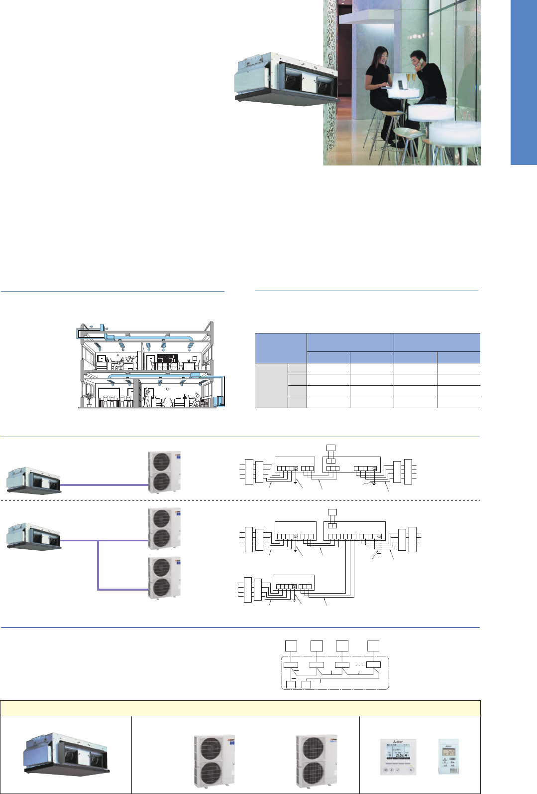
74
PEA
SERIES
For elegance and style, the PEA Series compliments the room environment with
an aesthetically pleasing ceiling installation and a vast line-up of performance
functions. Long pipe work installation is supported, increasing freedom in the
placement of indoor units.
S1 S2 S3
S1 S2 S3
G
I
L1 L2 L3 N
L1 L2 L3 N
1
D
2
A A
BBCC
E
G
H
I
F
PUHZ-200, 250 PEA-200, 250
Flexible Duct Design Enables Use
of High-pressure Static Fan
Long Refrigerant Piping Length
PAR-32MAA Group Control
Wide-ranging Line-up from 20–50kW – Extensive Array of Choices to Match Building Size
With the addition of more refrigerant, the maximum length for
refrigerant piping has been increased to 100 metres. As a result, it
is much easier to create the optimum layout for unit installation.
A flexible duct design and 150Pa external static high-pressure are
incorporated. The increased variation in airflow options ensures
operation that best
matches virtually all
room layouts.
[System Image]
• For PEA-200, 250
• For PEA-200, 250
PEA-RP200/250GAQ
PEA-RP400/500GAQ
• For PEA-400, 500
PEA-RP200/250/400/500GAQ
PEA-RP
Power Inverter
Connection
Standard Inverter
Connection
Max. Length Max. Height Max. Length Max. Height
200
250
400
500
100m
100m
100m
100m
30m
30m
30m
30m
70m
70m
70m
70m
30m
30m
30m
30m
A Power supply
BEarth leakage breaker
C Circuit breaker or local switch
DLCD remote controller
E Outdoor unit
F Indoor unit
G Power cable wiring
H Indoor/Outdoor connection wiring
I Grounding
A Outdoor unit
B
Indoor unit
C
Main remote controller
D
Subordinate remote controller
E
Standard (Refrigerant address = 00)
F
Refrigerant address = 01
G
Refrigerant address = 02
H Refrigerant address = 15
1
1
2
2 2
B BBB
EFGH
C
AAAA
D
G
H
H
S1 S2 S3 S1 S2 S3S1 S2 S3
S1 S2 S3
L1 L2 L3 N
L1 L2 L3 N
1
D
2
E
(No.1 Outdoor)
F
G
G
I
I
L1 L2 L3 N
E
(No.2 Outdoor)
I
PUHZ-200, 250 PEA-400, 500
PUHZ-200, 250
(TB4-1) (TB4-2)
A A
BBCC
ABC
LINE-UP
Indoor Unit Remote Controller
PUHZ-P200/250 OptionalOptional
PUHZ-ZRP200/250
PEA-RP200/250/400/500GAQ
Power
Inverter
Series
Standard
Inverter
Series
Outdoor Unit
✽
Two units are used when connecting PEA-RP400/500GAQ.
The PAR-32MAA remote controller can control up to
16 systems* as a group, and is ideal for supporting the
integrated management of building air conditioners.
*Count each set of PEA-RP400 and PEA-RP500 as two systems as
two outdoor units are connected.
75
Inverter Heat Pump
Outdoor power supply
400 / Three / 50
Type
Indoor Unit
Outdoor Unit
Refrigerant
Power
Supply
Cooling
Heating
Operating Current (max)
Indoor
Unit
Outdoor
Unit
Ext.
Piping
Guaranteed Operating Range
[Outdoo
Source
Outdoor (V/Phase/Hz)
Capacity
Total Input
EER
Capacity
Total Input
COP
Input [Cooling / Heating]
Operating Current (max)
Dimensions
Weight
Air Volume [Lo-Mid-Hi]
External Static Pressure
Sound Level (SPL) [Lo-Mid-Hi]
Sound Level (PWL)
Dimensions
Weight
Air Volume
Sound Level (SPL)
Sound Level (PWL)
Operating Current (max)
Breaker Size
Diameter
Max. Length
Max. Height
Rated
Min - Max
Rated
EEL Rank
Rated
Min - Max
Rated
EEL Rank
kW
kW
kW
kW
kW
kW
kW
A
mm
kg
m
3
/min
Pa
dB(A)
dB(A)
mm
kg
m
3
/min
m
3
/min
dB(A)
dB(A)
dB(A)
A
A
mm
m
m
o
C
o
C
PEA-RP200GAQ
PUHZ-ZRP200YKA
19.0
9.0 - 22.4
6.46
2.94
–
22.4
9.5 - 25.0
6.94
3.23
–
21.0
1.000
2.0
400 - 1400 - 634
70
52.0 - 65.0
150
48 - 51
15
135
140
140
59
62
77
19.0
32
9.52 / 25.4
100
30
-15 ~ +46
-20 ~ +21
PEA-RP400GAQ
PUHZ-ZRP200YKA x 2
38.0
18.0 - 44.8
12.47
3.05
–
44.8
18.0 - 50.0
13.43
3.34
–
41.8
1.550
3.8
130
120.0
150
52*
2
15
135
140
140
59
62
77
19.0
32
9.52 / 25.4
100
30
-15 ~ +46
-20 ~ +21
PEA-RP250GAQ
PUHZ-ZRP250YKA
22.0
11.2 - 27.0
8.31
2.65
–
27.0
12.5 - 31.0
8.94
3.02
–
23.3
1.180
2.3
400 - 1600 - 634
77
64.0 - 80.0
150
49 - 52
15
135
140
140
59
62
77
21.0
32
12.7 / 25.4
100
30
-15 ~ +46
-20 ~ +21
PEA-RP500GAQ
PUHZ-ZRP250YKA x 2
44.0
22.4 - 54.0
17.10
2.57
–
54.0
25.0- 62.0
18.36
2.94
–
47.4
2.840
5.4
133
160.0
150
53*
2
15
135
140
140
59
62
77
21.0
32
12.7 / 25.4
100
30
-15 ~ +46
-20 ~ +21
595 - 1947 - 764
1338 - 1050 - 330(+40) 1338 - 1050 - 330(+40)
*1 Refrigerant leakage contributes to climate change. Refrigerant with lower global warming potential (GWP) would contribute less to global warming than a refrigerant with higher GWP, if leaked to the atmosphere. This appliance
contains a refrigerant fluid with a GWP equal to 1975. This means that if 1 kg of this refrigerant fluid would be leaked to the atmosphere, the impact on global warming would be 1975 times higher than 1 kg of CO2, over a
period of 100 years. Never try to interfere with the refrigerant circuit yourself or disassemble the product yourself and always ask a professional.
*2 Energy consumption based on standard test results.Actual energy consumption will depend on how the appliance is used and where it is located.
*3 Optional air protection guide is required where ambient temperature is lower than -5°C.
*4 SEER/SCOP values are measured based on EN14825. These values are reference purpose only.
Inverter Heat Pump
Outdoor power supply
400 / Three / 50
Type
Indoor Unit
Outdoor Unit
Refrigerant
Power
Supply
Cooling
Heating
Operating Current (max)
Indoor
Unit
Outdoor
Unit
Ext.
Piping
Guaranteed Operating Range
[Outdoor]
Source
Outdoor (V/Phase/Hz)
Capacity
Total Input
EER
Capacity
Total Input
COP
Input [Cooling / Heating]
Operating Current (max)
Dimensions
Weight
Air Volume [Lo-Mid-Hi]
External Static Pressure
Sound Level (SPL) [Lo-Mid-Hi]
Sound Level (PWL)
Dimensions
Weight
Air Volume
Sound Level (SPL)
Sound Level (PWL)
Operating Current (max)
Breaker Size
Diameter
Max. Length
Max. Height
Rated
Min - Max
Rated
EEL Rank
Rated
Min - Max
Rated
EEL Rank
kW
kW
kW
kW
kW
kW
kW
A
mm
kg
m
3
/min
Pa
dB(A)
dB(A)
mm
kg
m
3
/min
m
3
/min
dB(A)
dB(A)
dB(A)
A
A
mm
m
m
o
C
o
C
PEA-RP200GAQ
PUHZ-P200YKA
19.0
9.0 - 22.4
6.64
2.86
–
22.4
9.5 - 25.0
7.10
3.15
–
21.0
1.000
2.0
400 - 1400 - 634
70
52.0 - 65.0
150
48 - 51
15
127
140
140
58
60
78
19.0
32
9.52 / 25.4
70
30
-15 ~ +46
-20 ~ +21
PEA-RP400GAQ
PUHZ-P200YKA x 2
38.0
18.0 - 44.8
12.83
2.96
–
44.8
18.0 - 50.0
13.75
3.26
–
41.8
1.550
3.8
130
120.0
150
52*
2
15
127
140
140
58
60
78
19.0
32
9.52 / 25.4
70
30
-15 ~ +46
-20 ~ +21
PEA-RP250GAQ
PUHZ-P250YKA
22.0
11.2 - 27.0
8.71
2.53
–
27.0
12.5 - 31.0
9.31
2.90
–
23.3
1.180
2.3
400 - 1600 - 634
77
64.0 - 80.0
150
49 - 52
15
135
140
140
59
62
77
21.0
32
12.7 / 25.4
70
30
-15 ~ +46
-20 ~ +21
PEA-RP500GAQ
PUHZ-P250YKA x 2
44.0
22.4 - 54.0
17.90
2.46
–
54.0
25.0- 62.0
19.10
2.83
–
47.4
2.840
5.4
133
160.0
150
53*
2
15
135
140
140
59
62
77
21.0
32
12.7 / 25.4
70
30
-15 ~ +46
-20 ~ +21
595 - 1947 - 764
1338 - 1050 - 330(+40) 1338 - 1050 - 330(+40)
*1 Refrigerant leakage contributes to climate change. Refrigerant with lower global warming potential (GWP) would contribute less to global warming than a refrigerant with higher GWP, if leaked to the atmosphere. This appliance
contains a refrigerant fluid with a GWP equal to 1975. This means that if 1 kg of this refrigerant fluid would be leaked to the atmosphere, the impact on global warming would be 1975 times higher than 1 kg of CO2
, over a
period of 100 years. Never try to interfere with the refrigerant circuit yourself or disassemble the product yourself and always ask a professional.
*2 Energy consumption based on standard test results.Actual energy consumption will depend on how the appliance is used and where it is located.
*3 Optional air protection guide is required where ambient temperature is lower than -5°C.
*4 SEER/SCOP values are measured based on EN14825. These values are reference purpose only.
R410A
*
1
Rated
H x W x D
H x W x D
Cooling
Heating
Cooling
Heating
Cooling
Liquid / Gas
Out-In
Out-In
Cooling
*
3
Heating
Rated
H x W x D
H x W x D
Cooling
Heating
Cooling
Heating
Cooling
Liquid / Gas
Out-In
Out-In
Cooling
*
3
Heating
(Average
Season)
(Average
Season)
R410A
*
1
Optional
Optional Optional
Optional
Optional
Optional OptionalOptional
Wi-Fi
Interface
Wi-Fi
Interface
POWER INVERTER
PEZ-RP SERIES
PEZ-P SERIES
STANDARD INVERTER
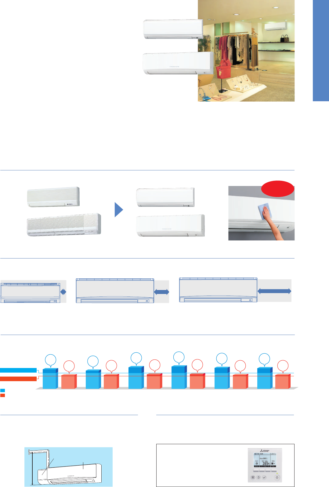
76
800mm
PKZ-RP HA/KA Indoor Unit Combinations
Indoor unit combinations shown below are possible.
Indoor Unit Combination
Power Inverter (PUHZ-ZRP)
Distribution Pipe
Standard Inverter (PUHZ-P )
Distribution Pipe
For Single
35
35x1
–
–
–
50x1
–
–
–
60x1
–
–
–
71x1
–
–
–
100x1
–
100x1
–
–
–
–
–
–
–
–
–
–
–
–
–
–
–
–
–
–
–
35x2
–
–
50x2
50x2
60x2
60x2
71x2
MSDD-50TR-E
71x2
MSDD-50TR-E
100x2
100x2
MSDD-50WR-E
–
MSDD-50WR-E
MSDF-1111R-E
MSDF-1111R-E
–
50x3
50x3
60x3
60x3
50x4
50x4
71x3
MSDT-111R-E
71x3
MSDT-111R-E
60x4
60x4
For Twin For Tr iple
For Quadruple
Outdoor Unit Capacity
50 60 71 100 125 140 200 250 71 100 125 140 200 250 140 200 250200 250
PUHZ-ZRP100PUHZ-ZRP60/71
PUHZ-ZRP100/125/140/200/250
PUHZ-ZRP71
PUHZ-ZRP35/50
PKA-RP35/50HAL
PKA-RP60/71/100KAL
PKA
SERIES
PKA-RP35/50HAL
PKA-RP60/71/100KAL
The compact, wall-mounted indoor units offer the convenience of simple installation,
and a large product line-up (RP35-RP100 models) ensures a best-match solution.
Designed for highly efficient energy savings, the PKA Series is the answer to your
air conditioning needs.
PKA-RP35/50HAL
PKA-RP60/71/100KAL
Flat Panel & Pure White Finish
A flat panel layout has been adopted for all models. Pursuing a design that harmonizes with virtually any interior, the unit colour has been changed
from white to pure white.
In addition to using the wireless remote controller that comes as
standard equipment, PAR-32MAA and PAC-YT52CRA wired remote
controllers can be used as well.
✽
Connection to PAR-32MAA/PAC-YT52CRA requires PAC-SH29TC-E (optional).
Multi-function Wired Remote Controller
Compact Indoor Units
Indoor unit width has been reduced by as much as 510mm (RP100). Units take up much less space, greatly increasing installation possibilities.
Drain pump
Indoor unit
PKA-RP HAL
PKA-RP KAL
PKA-RP GAL
PKA-RP35/50HAL
PKA-RP FAL
Installation of the drain pump enables a drain outlet as high as 800mm
above the base of the indoor unit. Drain water can be discharged easily
even if the surface where the wall-mounted unit does not have direct
access outside, increasing the degree of freedom for installation.
Drain Pump Option Available with All Models
PKA-RP60/71KAL
*Compared to PKA-RP35/50GAL *Compared to PKA-RP60/71FAL *Compared to PKA-RP100FAL
PKA-RP100KAL
92mm DOWN* 230mm DOWN* 510mm DOWN*
100-140
Grooved Piping
100-250
Vector-Wave
Flat panel is
easy to clean!
• Night Setback
• Energy- saving Mode
• Multi Language
•Weekly Timer
• Refrigerant Leak Check
✽
For details, please refer to pages 25-28.
Main Functions
SERIES SELECTION
Indoor Unit Outdoor Unit
Remote Controller
Power Inverter Series
Indoor Unit
Remote Controller
Standard Inverter Series
Outdoor Unit
Optional (
✽
) Optional (
✽
)
(
✽
) PAC-SH29TC-E is required (optional)
For Single
For Multi
(Twin/Triple/Quadruple)
For Multi
(Twin/Triple/Quadruple)
Optional (
✽
) Optional (
✽
)
PUHZ-P125/140 PUHZ-P200/250
PUHZ-P100
PUHZ-P100
ErP Lot 10 Compliant with High Energy-efficiency Achieving SEER/SCOP
Rank A, A
+
and A
++
Highly efficient indoor unit heat exchangers and and newly designed power inverters (PUHZ-ZRP) contribute to an amazing reduction in electricity
consumption throughout a year, and have resulted in models in the full-capacity range attaining the rank A, A
+
and A
++
energy savings rating.
Cooling
Heating
PKA-RP35HAL
PUHZ-ZRP35VKA
PKA-RP50HAL
PUHZ-ZRP50VKA
PKA-RP60KAL
PUHZ-ZRP60VHA
PKA-RP71KAL
PUHZ-ZRP71VHA
PKA-RP100KAL
PUHZ-ZRP100VKA2
PKA-RP100KAL
PUHZ-ZRP100YKA2
3.9
4.0
6.3
4.2
6.5
4.3
6.1
4.0
6.0
4.0
SEER
A
+
SCOP
A
SEER
A
SCOP
A
+
SEER
A
++
SCOP
A
+
SEER
A
++
SCOP
A
+
SEER
A
++
SCOP
A
++
SEER
A
+
SCOP
A
+
Minimum SCOP 3.8
Minimum SEER 4.6
For Single
5.7
5.3
35-140
Grooved Piping
Vector-Wave
35-71
Heat Caulking
Fixing Method
Joint Lap
35-71
Vector Sine Wave
DC Fan Motor
100-250
DC Scroll
Vector Sine Wave
100-250
DC Rotary
100-140
DC Fan Motor
200/250
DC Scroll
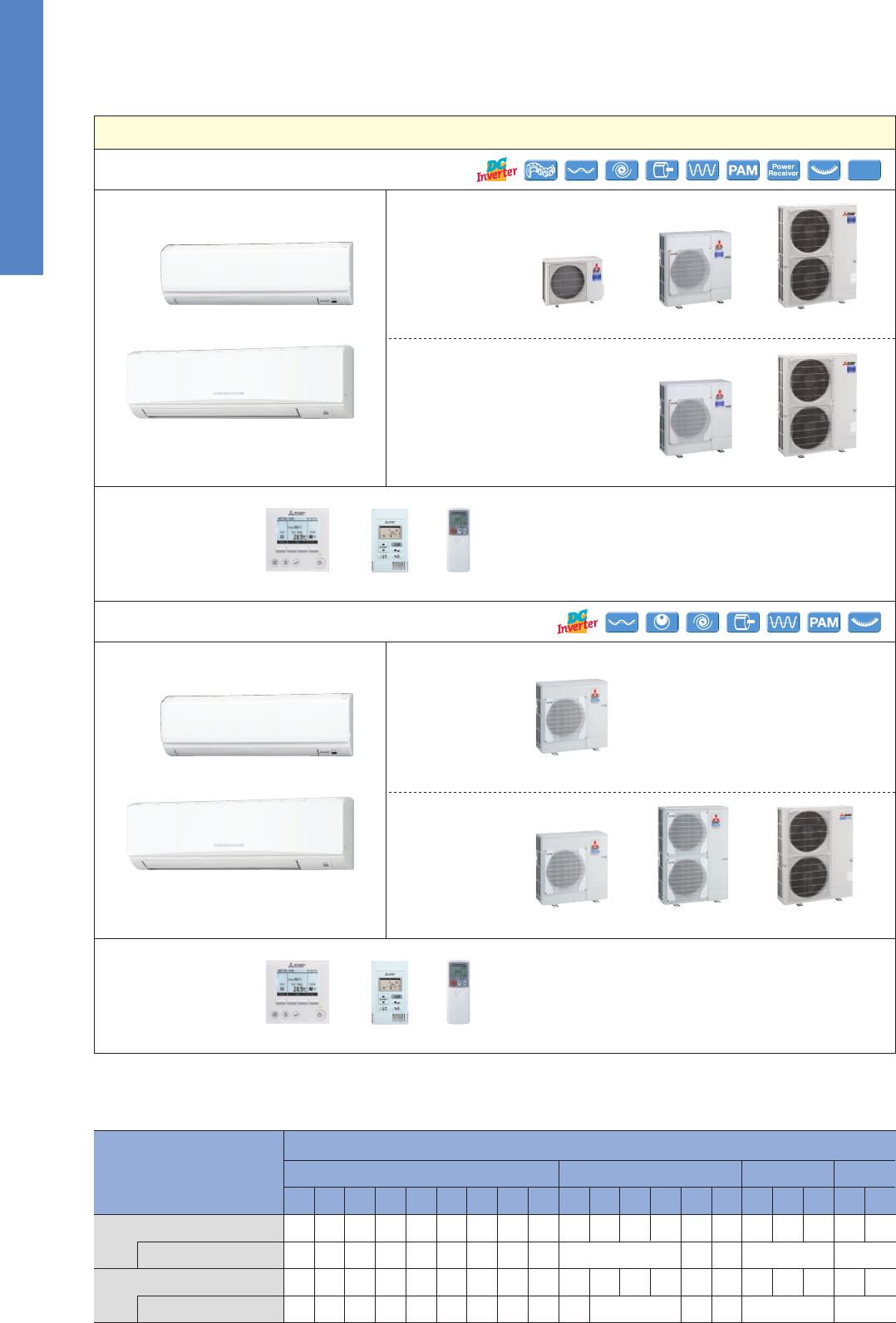
77
800mm
PKZ-RP HA/KA Indoor Unit Combinations
Indoor unit combinations shown below are possible.
Indoor Unit Combination
Power Inverter (PUHZ-ZRP)
Distribution Pipe
Standard Inverter (PUHZ-P )
Distribution Pipe
For Single
35
35x1
–
–
–
50x1
–
–
–
60x1
–
–
–
71x1
–
–
–
100x1
–
100x1
–
–
–
–
–
–
–
–
–
–
–
–
–
–
–
–
–
–
–
35x2
–
–
50x2
50x2
60x2
60x2
71x2
MSDD-50TR-E
71x2
MSDD-50TR-E
100x2
100x2
MSDD-50WR-E
–
MSDD-50WR-E
MSDF-1111R-E
MSDF-1111R-E
–
50x3
50x3
60x3
60x3
50x4
50x4
71x3
MSDT-111R-E
71x3
MSDT-111R-E
60x4
60x4
For Twin For Tr iple
For Quadruple
Outdoor Unit Capacity
50 60 71 100 125 140 200 250 71 100 125 140 200 250 140 200 250200 250
PUHZ-ZRP100PUHZ-ZRP60/71
PUHZ-ZRP100/125/140/200/250
PUHZ-ZRP71
PUHZ-ZRP35/50
PKA-RP35/50HAL
PKA-RP60/71/100KAL
PKA
SERIES
PKA-RP35/50HAL
PKA-RP60/71/100KAL
The compact, wall-mounted indoor units offer the convenience of simple installation,
and a large product line-up (RP35-RP100 models) ensures a best-match solution.
Designed for highly efficient energy savings, the PKA Series is the answer to your
air conditioning needs.
PKA-RP35/50HAL
PKA-RP60/71/100KAL
Flat Panel & Pure White Finish
A flat panel layout has been adopted for all models. Pursuing a design that harmonizes with virtually any interior, the unit colour has been changed
from white to pure white.
In addition to using the wireless remote controller that comes as
standard equipment, PAR-32MAA and PAC-YT52CRA wired remote
controllers can be used as well.
✽
Connection to PAR-32MAA/PAC-YT52CRA requires PAC-SH29TC-E (optional).
Multi-function Wired Remote Controller
Compact Indoor Units
Indoor unit width has been reduced by as much as 510mm (RP100). Units take up much less space, greatly increasing installation possibilities.
Drain pump
Indoor unit
PKA-RP HAL
PKA-RP KAL
PKA-RP GAL
PKA-RP35/50HAL
PKA-RP FAL
Installation of the drain pump enables a drain outlet as high as 800mm
above the base of the indoor unit. Drain water can be discharged easily
even if the surface where the wall-mounted unit does not have direct
access outside, increasing the degree of freedom for installation.
Drain Pump Option Available with All Models
PKA-RP60/71KAL
*Compared to PKA-RP35/50GAL *Compared to PKA-RP60/71FAL *Compared to PKA-RP100FAL
PKA-RP100KAL
92mm DOWN* 230mm DOWN* 510mm DOWN*
100-140
Grooved Piping
100-250
Vector-Wave
Flat panel is
easy to clean!
• Night Setback
• Energy- saving Mode
• Multi Language
•Weekly Timer
• Refrigerant Leak Check
✽
For details, please refer to pages 25-28.
Main Functions
SERIES SELECTION
Indoor Unit Outdoor Unit
Remote Controller
Power Inverter Series
Indoor Unit
Remote Controller
Standard Inverter Series
Outdoor Unit
Optional (
✽
) Optional (
✽
)
(
✽
) PAC-SH29TC-E is required (optional)
For Single
For Multi
(Twin/Triple/Quadruple)
For Multi
(Twin/Triple/Quadruple)
Optional (
✽
) Optional (
✽
)
PUHZ-P125/140 PUHZ-P200/250
PUHZ-P100
PUHZ-P100
ErP Lot 10 Compliant with High Energy-efficiency Achieving SEER/SCOP
Rank A, A
+
and A
++
Highly efficient indoor unit heat exchangers and and newly designed power inverters (PUHZ-ZRP) contribute to an amazing reduction in electricity
consumption throughout a year, and have resulted in models in the full-capacity range attaining the rank A, A
+
and A
++
energy savings rating.
Cooling
Heating
PKA-RP35HAL
PUHZ-ZRP35VKA
PKA-RP50HAL
PUHZ-ZRP50VKA
PKA-RP60KAL
PUHZ-ZRP60VHA
PKA-RP71KAL
PUHZ-ZRP71VHA
PKA-RP100KAL
PUHZ-ZRP100VKA2
PKA-RP100KAL
PUHZ-ZRP100YKA2
3.9
4.0
6.3
4.2
6.5
4.3
6.1
4.0
6.0
4.0
SEER
A
+
SCOP
A
SEER
A
SCOP
A
+
SEER
A
++
SCOP
A
+
SEER
A
++
SCOP
A
+
SEER
A
++
SCOP
A
++
SEER
A
+
SCOP
A
+
Minimum SCOP 3.8
Minimum SEER 4.6
For Single
5.7
5.3
35-140
Grooved Piping
Vector-Wave
35-71
Heat Caulking
Fixing Method
Joint Lap
35-71
Vector Sine Wave
DC Fan Motor
100-250
DC Scroll
Vector Sine Wave
100-250
DC Rotary
100-140
DC Fan Motor
200/250
DC Scroll
78
Inverter Heat Pump
Source
kW
Outdoor power supply
230 / Single / 50 400 / Three / 50
R410A*
1
PKA-RP100KAL
PUHZ-P100VHA4 PUHZ-P100YHA2
Type
Outdoor (V/Phase/Hz)
Power
Supply
Capacity
Total Input
Rated
Cooling
Heating
(Average
Season)
Operating Current (max)
Indoor
Unit
Outdoor
Unit
Indoor Unit
Outdoor Unit
Refrigerant
kW
Min - Max
kW
kW
kWh/a
Rated
Rated
Design Load
kW
Min - Max
kW
Rated
kW
kW
A
Capacity
Total Input
Design Load
kW
kW
kW
kW
kWh/a
kW
Declared Capacity
Back Up Heating Capacity
Annual Electricity Consumption
*
2
SCOP
Input Rated
A
Operating Current (max)
mm
Dimensions <Panel>
kg
Weight <Panel>
kg
Weight
m
3
/min
Air Volume [Lo-Mid-Hi]
dB(A)
Sound Level (SPL) [Lo-Mid-Hi]
dB(A)
Sound Level (PWL)
H × W × D
mm
Dimensions H × W × D
Ext.
Piping
mm
Diameter Liquid / Gas
Guaranteed Operating Range
[Outdoor]
°C
Cooling
*
3
°C
Heating
m
Max. Length Out-In
m
Max. Height Out-In
m
3
/min
Air Volume Cooling
m
3
/min
Heating
dB(A)
dB(A)
dB(A)
Sound Level (SPL)
Cooling
Sound Level (PWL)
Cooling
A
Operating Current (max)
A
Breaker Size
Heating
at reference design temperature
at bivalent temperature
at operation limit temperature
Energy Efficiency Class
Energy Efficiency Class
SEER
Annual Electricity Consumption
*
2
*1 Refrigerant leakage contributes to climate change. Refrigerant with lower global warming potential (GWP) would contribute less to global warming than a refrigerant with higher GWP, if leaked to the atmosphere. This appliance
contains a refrigerant fluid with a GWP equal to 1975. This means that if 1kg of this refrigerant fluid would be leaked to the atmosphere, the impact on global warming would be 1975 times higher than 1kg of CO2, over a period
of 100 years. Never try to interfere with the refrigerant circuit yourself or disassemble the product yourself and always ask a professional.
*2 Energy consumption based on standard test results. Actual energy consumption will depend on how the appliance is used and where it is located.
*3 Optional air protection guide is required where ambient temperature is lower than –5°C. *4 SEER/SCOP values are measured based on EN14825. These values are reference purpose only.
Inverter Heat Pump
Source
kW 3.6
1.6 - 4.5
0.94
–
–
3.6
221
5.7
A+
4.1
1.6 - 5.2
1.07
–
–
2.4
2.4 (–10°C)
2.4 (–10°C)
2.2 (–11°C)
0
847
3.9
A
13.4
0.04
0.4
13
9 - 10.5 - 12
36 - 40 - 43
60
43
45.0
45.0
44
46
65
13.0
16
6.35 / 12.7
50
30
–15 ~ +46
–11 ~ +21
4.6
2.3 - 5.6
1.41
–
–
4.6
304
5.3
A
5.0
2.5 - 7.3
1.50
–
–
3.3
3.3 (–10°C)
3.3 (–10°C)
3.2 (–11°C)
0
1160
4.0
A
+
13.4
0.04
0.4
13
9 - 10.5 - 12
36 - 40 - 43
60
46
45.0
45.0
44
46
65
13.0
16
6.35 / 12.7
50
30
–15 ~ +46
–11 ~ +21
6.1
2.7 - 6.7
1.60
–
–
6.1
336
6.3
A
++
7.0
2.8 - 8.2
1.96
–
–
4.4
4.4 (–10°C)
4.4 (–10°C)
2.8 (–20°C)
0
1473
4.2
A
+
19.4
0.06
0.43
21
18 - 20 - 22
39 - 42 - 45
64
67
55.0
55.0
47
48
67
19.0
25
9.52 / 15.88
50
30
–15 ~ +46
–20 ~ +21
7.1
3.3 - 8.1
1.80
–
–
7.1
381
6.5
A
++
8.0
3.5 - 10.2
2.19
–
–
4.7
4.7 (–10°C)
4.7 (–10°C)
3.5 (–20°C)
0
1532
4.3
A
+
19.4
0.06
0.43
21
18 - 20 - 22
39 - 42 - 45
64
67
55.0
55.0
47
48
67
19.0
25
9.52 / 15.88
50
30
–15 ~ +46
–20 ~ +21
9.5
4.9 - 11.4
2.40
–
–
9.5
539
6.1
A
++
11.2
4.5 - 14.0
3.04
–
–
7.8
7.8 (–10°C)
7.8 (–10°C)
5.8 (–20°C)
0
2608
4.1
A
+
27.1
0.08
0.57
21
20 - 23 - 26
41 - 45 - 49
65
116
110.0
110.0
49
51
69
26.5
32
9.52 / 15.88
75
30
–15 ~ +46
–20 ~ +21
9.5
4.9 - 11.4
2.40
–
–
9.5
550
6.0
A
+
11.2
4.5 - 14.0
3.04
–
–
7.8
7.8 (–10°C)
7.8 (–10°C)
5.8 (–20°C)
0
2608
4.1
A
+
8.6
0.08
0.57
21
20 - 23 - 26
41 - 45 - 49
65
123
110.0
110.0
49
51
69
8.0
16
9.52 / 15.88
75
30
–15 ~ +46
–20 ~ +21
Outdoor power supply
VKA
•
VHA:230 / Single / 50, YKA:400 / Three / 50
R410A*
1
PKA-RP35HAL PKA-RP50HAL PKA-RP60KAL PKA-RP71KAL PKA-RP100KAL
PUHZ-ZRP35VKAPUHZ-ZRP50VKAPUHZ-ZRP60VHAPUHZ-ZRP71VHAPUHZ-ZRP100VKA2 PUHZ-ZRP100YKA2
Type
Outdoor (V/Phase/Hz)
Power
Supply
Capacity
Total Input
Rated
Cooling
Heating
(Average
Season)
Operating Current (max)
Indoor
Unit
Outdoor
Unit
Indoor Unit
Outdoor Unit
Refrigerant
kW
Min - Max
kW
kW
kWh/a
Rated
Rated
EEL Rank
EER
Design Load
kW
Min - Max
kW
Rated
kW
kW
A
Capacity
Total Input
COP
Design Load
kW
kW
kW
kW
kWh/a
kW
Declared Capacity
Back Up Heating Capacity
Annual Electricity Consumption
*
2
SCOP
Input Rated
A
Operating Current (max)
mm
Dimensions <Panel>
kg
Weight <Panel>
kg
Weight
m
3
/min
Air Volume [Lo-Mid-Hi]
dB(A)
Sound Level (SPL) [Lo-Mid-Hi]
dB(A)
Sound Level (PWL)
H × W × D
mm
Dimensions H × W × D
Ext.
Piping
mm
Diameter Liquid / Gas
Guaranteed Operating Range
[Outdoor]
°C
Cooling
*
3
°C
Heating
m
Max. Length Out-In
m
Max. Height Out-In
m
3
/min
Air Volume Cooling
m
3
/min
Heating
dB(A)
dB(A)
dB(A)
Sound Level (SPL)
Cooling
Sound Level (PWL)
Cooling
A
Operating Current (max)
A
Breaker Size
Heating
EEL Rank
at reference design temperature
at bivalent temperature
at operation limit temperature
Energy Efficiency Class
Energy Efficiency Class
SEER
Annual Electricity Consumption
*
2
*1 Refrigerant leakage contributes to climate change. Refrigerant with lower global warming potential (GWP) would contribute less to global warming than a refrigerant with higher GWP, if leaked to the atmosphere. This appliance
contains a refrigerant fluid with a GWP equal to 1975. This means that if 1kg of this refrigerant fluid would be leaked to the atmosphere, the impact on global warming would be 1975 times higher than 1kg of CO2, over a period
of 100 years. Never try to interfere with the refrigerant circuit yourself or disassemble the product yourself and always ask a professional.
*2 Energy consumption based on standard test results. Actual energy consumption will depend on how the appliance is used and where it is located.
*3 Optional air protection guide is required where ambient temperature is lower than –5°C. *4 SEER/SCOP values are measured based on EN14825. These values are reference purpose only.
295 - 898 - 249
630 - 809 - 300 943 - 950 - 330 (+30) 1338 - 1050 - 330 (+40)
365 - 1170 - 295
9.4
4.9 - 11.2
3.120
9.4
686
4.8
B
11.2
4.5 - 12.5
3.490
7.0
5.6 (–10°C)
6.2 (–7°C)
4.5 (–15°C)
1.4
2579
3.8
A
28.6
0.08
0.57
21
20 - 23 - 26
41 - 45 - 49
65
75
60.0
60.0
50
54
70
28.0
32
9.52 / 15.88
50
30
–15 ~ +46
–15 ~ +21
9.4
4.9 - 11.2
3.120
9.4
686
4.8
B
11.2
4.5 - 12.5
3.490
7.0
5.6 (–10°C)
6.2 (–7°C)
4.5 (–15°C)
1.4
2579
3.8
A
13.6
0.08
0.57
21
20 - 23 - 26
41 - 45 - 49
65
77
60.0
60.0
50
54
70
13.0
16
9.52 / 15.88
50
30
–15 ~ +46
–15 ~ +21
365 - 1170 - 295
943 - 950 - 330 (+30)
Optional Optional
60-140V/200/250
Optional Optional
Optional
OptionalOptional Optional
Wi-Fi
Interface
Optional Optional
Optional Optional
Optional
Optional Optional
Optional Optional
Capacity
High
ceiling
Standard
ceiling
Low
ceiling
35
50
60
71
100
125
140
3.5m
3.5m
3.5m
3.5m
4.2m
4.2m
4.2m
2.7m
2.7m
2.7m
2.7m
3.0m
3.0m
3.0m
2.5m
2.5m
2.5m
2.5m
2.6m
2.6m
2.6m
PCA-KA
SERIES
A stylish new indoor unit design and airflow settings for both high- and low-ceiling
interiors expand installation possibilities. Together with exceptional energy-saving
performance, these units are the solution to diversified air conditioning needs.
Stylish Indoor Unit Design
A stylish square-like design is adopted for the indoor units of all models. As a result,
the units blend in better with the ceiling.
The pumping height of the op-
tional drain pump has been in-
creased from 400mm to 600mm,
expanding flexibility in choosing
unit location during installation
work.
Optional Drain Pump for Full-capacity Models
In addition to the conventional 4-speed setting, units are now equipped
with an automatic air-speed adjustment mode. This setting automati-
cally adjusts the air-speed to conditions that match the room environ-
ment. At the start of heating/cooling operation, the airflow is set to
high-speed to quickly heat/cool the room. When the room tempera-
ture reaches the desired setting, the airflow speed is decreased auto-
matically for stable comfortable heating/cooling operation.
Equipped with Automatic Air-speed Adjustment
Units are equipped with
a knock-out hole that
enables the induction of
fresh outside-air.
Outside-air Intake
Units are equipped with high- and low-ceiling operation modes that
make it possible to switch the airflow volume to match room height.
The ability to choose the optimum airflow volume makes it possible
to optimize the breezy sensation felt throughout the room.
Equipped with High- /Low-ceiling Modes
PCA-RP35/50/60/71/100/125/140KAQ
PCA-GA PCA-KAQ
Drainage outlet
can be 600mm
above ceiling
surface
●
Drain pump
installation possible
Airflow volume (m
3
/min)
50
0
–50
– 100
– 150
– 200
– 250
– 300
01 234
Static pressure (Pa)
●
Outside-air intake characteristics
Ceiling surface
Start of cooling/heating… After room temperature is stabilized…
PCA-RP100-140KAQ
PCA-RP60/71KAQ
PCA-RP35/50KAQ
RP100–140
PCA-RP60/71KAQ
PCA-RP35/50KAQ
Strong Gentle
PCA-RP35KAQ
PUHZ-ZRP35VKA
PCA-RP50KAQ
PUHZ-ZRP50VKA
PCA-RP60KAQ
PUHZ-ZRP60VHA
PCA-RP71KAQ
PUHZ-ZRP71VHA
PCA-RP100KAQ
PUHZ-ZRP100VKA2
PCA-RP100KAQ
PUHZ-ZRP100YKA2
PCA-RP125KAQ
PUHZ-ZRP125VKA2
PCA-RP125KAQ
PUHZ-ZRP125YKA2
PCA-RP140KAQ
PUHZ-ZRP140VKA2
PCA-RP140KAQ
PUHZ-ZRP140YKA2
✽
For products with capacity over 10.0kW, SEER/SCOP values are measured based on EN14825. These values are for reference purposes only.
ErP Lot 10 Compliant with High Energy-efficiency Achieving SEER/SCOP Rank A, A
+
and A
++
A direct-current (DC) fan motor is isntalled in the indoor unit, increasing the seasonal energy efficiency of newly designed Power Inverter series
(PUHZ-ZRP) and resulting in the full capacity models comply ErP Lot 10 with energy ranking A
+
/A
++
for cooling and A/A
+
for heating. This contrib-
ute to an impressive reduction in the cost of annual electricity.
Cooling
Heating
6.1
4.1
SEER
A
++
SCOP
A
+
6.0
4.2
SEER
A
+
SCOP
A
+
6.2
4.3
SEER
A
++
SCOP
A
+
6.6
4.3
SEER
A
++
SCOP
A
+
6.0
3.9
SEER
A
+
SCOP
A
5.9
3.9
SEER
A
+
SCOP
A
5.2
4.2
5.2
4.2
5.3
4.4
5.2
4.4
Optional
Wi-Fi
Interface
Minimum SCOP 3.8
Minimum SEER 4.6
POWER INVERTER
PKZ-RP SERIES
Please fill out the requested information
Please fill out the requested information
STANDARD INVERTER
PKZ-P SERIES
Please fill out the requested information
Please fill out the requested information
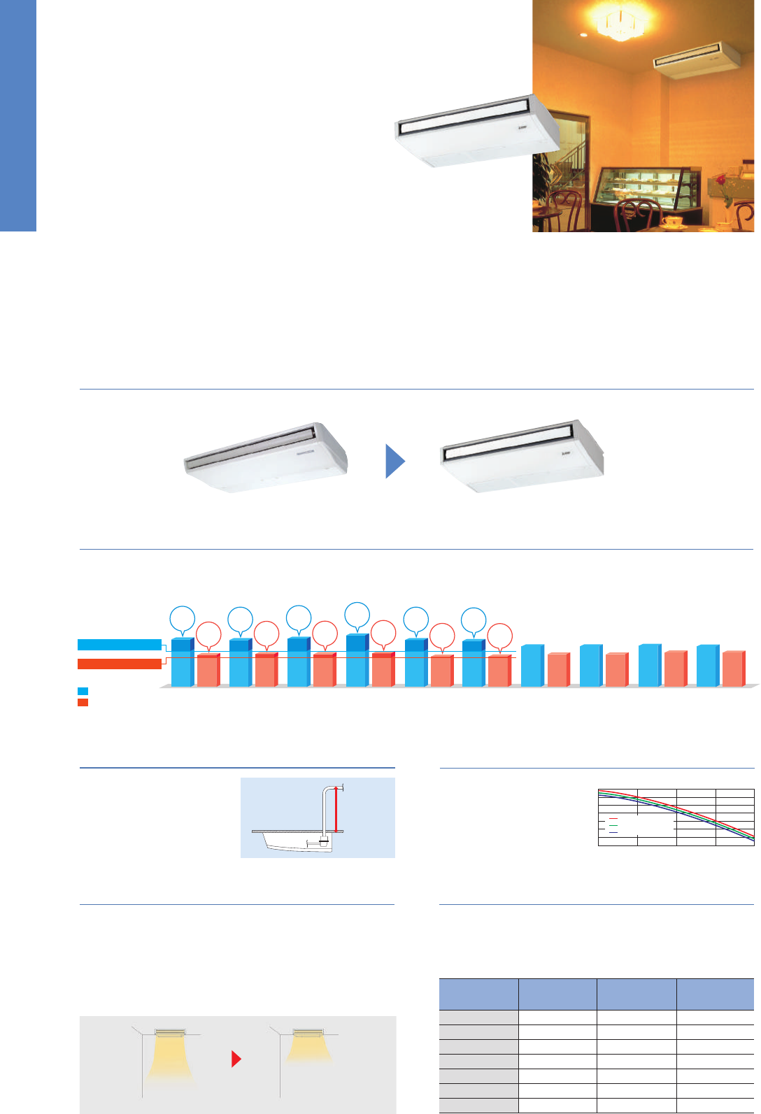
79
Inverter Heat Pump
Source
kW
Outdoor power supply
230 / Single / 50 400 / Three / 50
R410A*
1
PKA-RP100KAL
PUHZ-P100VHA4 PUHZ-P100YHA2
Type
Outdoor (V/Phase/Hz)
Power
Supply
Capacity
Total Input
Rated
Cooling
Heating
(Average
Season)
Operating Current (max)
Indoor
Unit
Outdoor
Unit
Indoor Unit
Outdoor Unit
Refrigerant
kW
Min - Max
kW
kW
kWh/a
Rated
Rated
Design Load
kW
Min - Max
kW
Rated
kW
kW
A
Capacity
Total Input
Design Load
kW
kW
kW
kW
kWh/a
kW
Declared Capacity
Back Up Heating Capacity
Annual Electricity Consumption
*
2
SCOP
Input Rated
A
Operating Current (max)
mm
Dimensions <Panel>
kg
Weight <Panel>
kg
Weight
m
3
/min
Air Volume [Lo-Mid-Hi]
dB(A)
Sound Level (SPL) [Lo-Mid-Hi]
dB(A)
Sound Level (PWL)
H × W × D
mm
Dimensions H × W × D
Ext.
Piping
mm
Diameter Liquid / Gas
Guaranteed Operating Range
[Outdoor]
°C
Cooling
*
3
°C
Heating
m
Max. Length Out-In
m
Max. Height Out-In
m
3
/min
Air Volume Cooling
m
3
/min
Heating
dB(A)
dB(A)
dB(A)
Sound Level (SPL)
Cooling
Sound Level (PWL)
Cooling
A
Operating Current (max)
A
Breaker Size
Heating
at reference design temperature
at bivalent temperature
at operation limit temperature
Energy Efficiency Class
Energy Efficiency Class
SEER
Annual Electricity Consumption
*
2
*1 Refrigerant leakage contributes to climate change. Refrigerant with lower global warming potential (GWP) would contribute less to global warming than a refrigerant with higher GWP, if leaked to the atmosphere. This appliance
contains a refrigerant fluid with a GWP equal to 1975. This means that if 1kg of this refrigerant fluid would be leaked to the atmosphere, the impact on global warming would be 1975 times higher than 1kg of CO2, over a period
of 100 years. Never try to interfere with the refrigerant circuit yourself or disassemble the product yourself and always ask a professional.
*2 Energy consumption based on standard test results. Actual energy consumption will depend on how the appliance is used and where it is located.
*3 Optional air protection guide is required where ambient temperature is lower than –5°C. *4 SEER/SCOP values are measured based on EN14825. These values are reference purpose only.
Inverter Heat Pump
Source
kW 3.6
1.6 - 4.5
0.94
–
–
3.6
221
5.7
A+
4.1
1.6 - 5.2
1.07
–
–
2.4
2.4 (–10°C)
2.4 (–10°C)
2.2 (–11°C)
0
847
3.9
A
13.4
0.04
0.4
13
9 - 10.5 - 12
36 - 40 - 43
60
43
45.0
45.0
44
46
65
13.0
16
6.35 / 12.7
50
30
–15 ~ +46
–11 ~ +21
4.6
2.3 - 5.6
1.41
–
–
4.6
304
5.3
A
5.0
2.5 - 7.3
1.50
–
–
3.3
3.3 (–10°C)
3.3 (–10°C)
3.2 (–11°C)
0
1160
4.0
A
+
13.4
0.04
0.4
13
9 - 10.5 - 12
36 - 40 - 43
60
46
45.0
45.0
44
46
65
13.0
16
6.35 / 12.7
50
30
–15 ~ +46
–11 ~ +21
6.1
2.7 - 6.7
1.60
–
–
6.1
336
6.3
A
++
7.0
2.8 - 8.2
1.96
–
–
4.4
4.4 (–10°C)
4.4 (–10°C)
2.8 (–20°C)
0
1473
4.2
A
+
19.4
0.06
0.43
21
18 - 20 - 22
39 - 42 - 45
64
67
55.0
55.0
47
48
67
19.0
25
9.52 / 15.88
50
30
–15 ~ +46
–20 ~ +21
7.1
3.3 - 8.1
1.80
–
–
7.1
381
6.5
A
++
8.0
3.5 - 10.2
2.19
–
–
4.7
4.7 (–10°C)
4.7 (–10°C)
3.5 (–20°C)
0
1532
4.3
A
+
19.4
0.06
0.43
21
18 - 20 - 22
39 - 42 - 45
64
67
55.0
55.0
47
48
67
19.0
25
9.52 / 15.88
50
30
–15 ~ +46
–20 ~ +21
9.5
4.9 - 11.4
2.40
–
–
9.5
539
6.1
A
++
11.2
4.5 - 14.0
3.04
–
–
7.8
7.8 (–10°C)
7.8 (–10°C)
5.8 (–20°C)
0
2608
4.1
A
+
27.1
0.08
0.57
21
20 - 23 - 26
41 - 45 - 49
65
116
110.0
110.0
49
51
69
26.5
32
9.52 / 15.88
75
30
–15 ~ +46
–20 ~ +21
9.5
4.9 - 11.4
2.40
–
–
9.5
550
6.0
A
+
11.2
4.5 - 14.0
3.04
–
–
7.8
7.8 (–10°C)
7.8 (–10°C)
5.8 (–20°C)
0
2608
4.1
A
+
8.6
0.08
0.57
21
20 - 23 - 26
41 - 45 - 49
65
123
110.0
110.0
49
51
69
8.0
16
9.52 / 15.88
75
30
–15 ~ +46
–20 ~ +21
Outdoor power supply
VKA
•
VHA:230 / Single / 50, YKA:400 / Three / 50
R410A*
1
PKA-RP35HAL PKA-RP50HAL PKA-RP60KAL PKA-RP71KAL PKA-RP100KAL
PUHZ-ZRP35VKAPUHZ-ZRP50VKAPUHZ-ZRP60VHAPUHZ-ZRP71VHAPUHZ-ZRP100VKA2 PUHZ-ZRP100YKA2
Type
Outdoor (V/Phase/Hz)
Power
Supply
Capacity
Total Input
Rated
Cooling
Heating
(Average
Season)
Operating Current (max)
Indoor
Unit
Outdoor
Unit
Indoor Unit
Outdoor Unit
Refrigerant
kW
Min - Max
kW
kW
kWh/a
Rated
Rated
EEL Rank
EER
Design Load
kW
Min - Max
kW
Rated
kW
kW
A
Capacity
Total Input
COP
Design Load
kW
kW
kW
kW
kWh/a
kW
Declared Capacity
Back Up Heating Capacity
Annual Electricity Consumption
*
2
SCOP
Input Rated
A
Operating Current (max)
mm
Dimensions <Panel>
kg
Weight <Panel>
kg
Weight
m
3
/min
Air Volume [Lo-Mid-Hi]
dB(A)
Sound Level (SPL) [Lo-Mid-Hi]
dB(A)
Sound Level (PWL)
H × W × D
mm
Dimensions H × W × D
Ext.
Piping
mm
Diameter Liquid / Gas
Guaranteed Operating Range
[Outdoor]
°C
Cooling
*
3
°C
Heating
m
Max. Length Out-In
m
Max. Height Out-In
m
3
/min
Air Volume Cooling
m
3
/min
Heating
dB(A)
dB(A)
dB(A)
Sound Level (SPL)
Cooling
Sound Level (PWL)
Cooling
A
Operating Current (max)
A
Breaker Size
Heating
EEL Rank
at reference design temperature
at bivalent temperature
at operation limit temperature
Energy Efficiency Class
Energy Efficiency Class
SEER
Annual Electricity Consumption
*
2
*1 Refrigerant leakage contributes to climate change. Refrigerant with lower global warming potential (GWP) would contribute less to global warming than a refrigerant with higher GWP, if leaked to the atmosphere. This appliance
contains a refrigerant fluid with a GWP equal to 1975. This means that if 1kg of this refrigerant fluid would be leaked to the atmosphere, the impact on global warming would be 1975 times higher than 1kg of CO2, over a period
of 100 years. Never try to interfere with the refrigerant circuit yourself or disassemble the product yourself and always ask a professional.
*2 Energy consumption based on standard test results. Actual energy consumption will depend on how the appliance is used and where it is located.
*3 Optional air protection guide is required where ambient temperature is lower than –5°C. *4 SEER/SCOP values are measured based on EN14825. These values are reference purpose only.
295 - 898 - 249
630 - 809 - 300 943 - 950 - 330 (+30) 1338 - 1050 - 330 (+40)
365 - 1170 - 295
9.4
4.9 - 11.2
3.120
9.4
686
4.8
B
11.2
4.5 - 12.5
3.490
7.0
5.6 (–10°C)
6.2 (–7°C)
4.5 (–15°C)
1.4
2579
3.8
A
28.6
0.08
0.57
21
20 - 23 - 26
41 - 45 - 49
65
75
60.0
60.0
50
54
70
28.0
32
9.52 / 15.88
50
30
–15 ~ +46
–15 ~ +21
9.4
4.9 - 11.2
3.120
9.4
686
4.8
B
11.2
4.5 - 12.5
3.490
7.0
5.6 (–10°C)
6.2 (–7°C)
4.5 (–15°C)
1.4
2579
3.8
A
13.6
0.08
0.57
21
20 - 23 - 26
41 - 45 - 49
65
77
60.0
60.0
50
54
70
13.0
16
9.52 / 15.88
50
30
–15 ~ +46
–15 ~ +21
365 - 1170 - 295
943 - 950 - 330 (+30)
Optional Optional
60-140V/200/250
Optional Optional
Optional
OptionalOptional Optional
Wi-Fi
Interface
Optional Optional
Optional Optional
Optional
Optional Optional
Optional Optional
Capacity
High
ceiling
Standard
ceiling
Low
ceiling
35
50
60
71
100
125
140
3.5m
3.5m
3.5m
3.5m
4.2m
4.2m
4.2m
2.7m
2.7m
2.7m
2.7m
3.0m
3.0m
3.0m
2.5m
2.5m
2.5m
2.5m
2.6m
2.6m
2.6m
PCA-KA
SERIES
A stylish new indoor unit design and airflow settings for both high- and low-ceiling
interiors expand installation possibilities. Together with exceptional energy-saving
performance, these units are the solution to diversified air conditioning needs.
Stylish Indoor Unit Design
A stylish square-like design is adopted for the indoor units of all models. As a result,
the units blend in better with the ceiling.
The pumping height of the op-
tional drain pump has been in-
creased from 400mm to 600mm,
expanding flexibility in choosing
unit location during installation
work.
Optional Drain Pump for Full-capacity Models
In addition to the conventional 4-speed setting, units are now equipped
with an automatic air-speed adjustment mode. This setting automati-
cally adjusts the air-speed to conditions that match the room environ-
ment. At the start of heating/cooling operation, the airflow is set to
high-speed to quickly heat/cool the room. When the room tempera-
ture reaches the desired setting, the airflow speed is decreased auto-
matically for stable comfortable heating/cooling operation.
Equipped with Automatic Air-speed Adjustment
Units are equipped with
a knock-out hole that
enables the induction of
fresh outside-air.
Outside-air Intake
Units are equipped with high- and low-ceiling operation modes that
make it possible to switch the airflow volume to match room height.
The ability to choose the optimum airflow volume makes it possible
to optimize the breezy sensation felt throughout the room.
Equipped with High- /Low-ceiling Modes
PCA-RP35/50/60/71/100/125/140KAQ
PCA-GA PCA-KAQ
Drainage outlet
can be 600mm
above ceiling
surface
●
Drain pump
installation possible
Airflow volume (m
3
/min)
50
0
–50
– 100
– 150
– 200
– 250
– 300
01 234
Static pressure (Pa)
●
Outside-air intake characteristics
Ceiling surface
Start of cooling/heating… After room temperature is stabilized…
PCA-RP100-140KAQ
PCA-RP60/71KAQ
PCA-RP35/50KAQ
RP100–140
PCA-RP60/71KAQ
PCA-RP35/50KAQ
Strong Gentle
PCA-RP35KAQ
PUHZ-ZRP35VKA
PCA-RP50KAQ
PUHZ-ZRP50VKA
PCA-RP60KAQ
PUHZ-ZRP60VHA
PCA-RP71KAQ
PUHZ-ZRP71VHA
PCA-RP100KAQ
PUHZ-ZRP100VKA2
PCA-RP100KAQ
PUHZ-ZRP100YKA2
PCA-RP125KAQ
PUHZ-ZRP125VKA2
PCA-RP125KAQ
PUHZ-ZRP125YKA2
PCA-RP140KAQ
PUHZ-ZRP140VKA2
PCA-RP140KAQ
PUHZ-ZRP140YKA2
✽
For products with capacity over 10.0kW, SEER/SCOP values are measured based on EN14825. These values are for reference purposes only.
ErP Lot 10 Compliant with High Energy-efficiency Achieving SEER/SCOP Rank A, A
+
and A
++
A direct-current (DC) fan motor is isntalled in the indoor unit, increasing the seasonal energy efficiency of newly designed Power Inverter series
(PUHZ-ZRP) and resulting in the full capacity models comply ErP Lot 10 with energy ranking A
+
/A
++
for cooling and A/A
+
for heating. This contrib-
ute to an impressive reduction in the cost of annual electricity.
Cooling
Heating
6.1
4.1
SEER
A
++
SCOP
A
+
6.0
4.2
SEER
A
+
SCOP
A
+
6.2
4.3
SEER
A
++
SCOP
A
+
6.6
4.3
SEER
A
++
SCOP
A
+
6.0
3.9
SEER
A
+
SCOP
A
5.9
3.9
SEER
A
+
SCOP
A
5.2
4.2
5.2
4.2
5.3
4.4
5.2
4.4
Optional
Wi-Fi
Interface
Minimum SCOP 3.8
Minimum SEER 4.6
POWER INVERTER
PKZ-RP SERIES
Please fill out the requested information
Please fill out the requested information
STANDARD INVERTER
PKZ-P SERIES
Please fill out the requested information
Please fill out the requested information
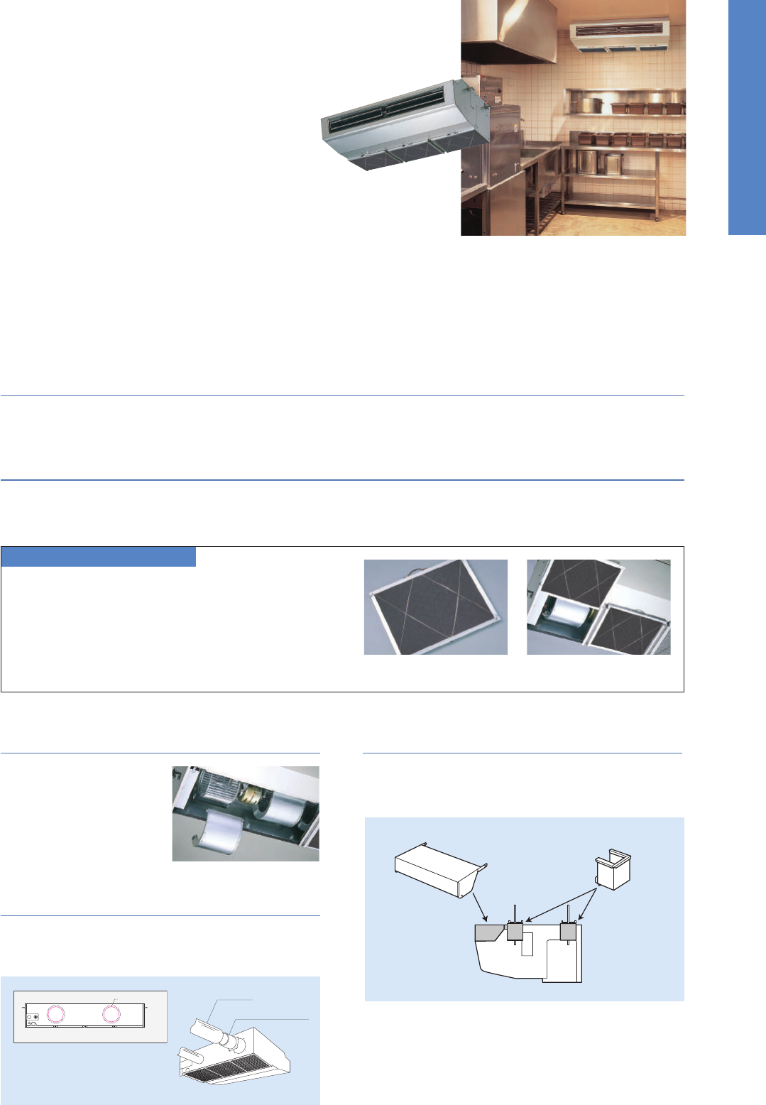
80
PCA-HA
SERIES
Standard features include a strong carbon-black stainless steel body and built-in
oil mist filter to prevent oil from getting into the unit providing a comfortable air
conditioning environment in kitchens that use open-flame cooking.
Tough on Oily Smoke
A durable stainless steel casing that is resistant to oil and grease is provided to protect the surface of the body. Grimy dirt and stains are removed
easily, enabling the unit to be kept clean at all times.
High-performance Oil Mist Filter
A high-performance heavy-duty oil mist filter is included as standard equipment. The filtering system is more efficient than conventional filters,
thereby effectively reducing the oily smoke entering the air conditioner. The filter is disposable, thereby enabling trouble-free cleaning and mainte-
nance.
Oil Mist Filter Cleaning
When used in kitchens, the oil mist filter should be replaced
once every two months. The system comes with 12 filters
elements. After these have been used, optional elements
(PAC-SG38KF-E) can be purchased.
A separate fan casing that can be
disassembled in sections is ad-
opted to ensure easy fan clean-
ing. Drain pan cleaning onsite is
also no problem owing to the
use of a pipe connector that is
easily removed.
Easy Maintenance –
Even for Cleaning the Fan
Fresh Outside-air Intake (Option)
There is a knock-out opening on the rear panel of the unit that can
be used to bring fresh air into the unit. This helps to improve ventila-
tion and make the kitchen comfortable.
Oil mist filter Pull the handle to easily slide
the filter out
Cosmetic covers are available to prevent the collection of dust and
grime on the main body and hanging fixture sections.
Cosmetic Front and
Hanging Fixture Covers (Option)
Notes: 1) A fresh-air duct flange is required (sold separately)
2) Intake air is not 100% fresh (outside) air.
PCA-RP71HAQ
Front cover Hanging fixture cover
PCZ-RP HA Indoor Unit Combinations
Indoor unit combinations shown below are possible.
Indoor Unit Combination
Power Inverter (PUHZ-ZRP)
Distribution Pipe
Standard Inverter (PUHZ-P )
Distribution Pipe
For Single
35
–
–
–
–
–
–
–
–
–
–
–
–
71x1
–
–
–
–
–
–
–
–
–
–
–
–
–
–
–
–
–
–
–
–
––
–
–
–
–
–
–
–
–
–
–
–
–
–
–
–
–
–
–
–
71x2
MSDD-50TR-E
71x2
MSDD-50TR-E
–
–
–
–
–
–
–
–
–
–
–
–
–
–
–
–
–
–
71x3
MSDT-111R-E
71x3
MSDT-111R-E
For Twin For Tr iple
For Quadruple
Outdoor Unit Capacity
50 60 71 100 125 140 200 250 71 100 125 140 200 250 140 200 250200 250
SERIES SELECTION
Indoor Unit Outdoor Unit
For Single
For Multi (Twin/Triple)
Remote Controller
Power Inverter Series
PUHZ-ZRP71
PUHZ-ZRP140/250
PCA-RP71HAQ
Grooved Piping
OptionalOptionalOptional
PCZ-RP KA Indoor Unit Combinations
Indoor unit combinations shown below are possible.
Indoor Unit Combination
Power Inverter (PUHZ-ZRP)
Distribution Pipe
Standard Inverter (PUHZ-P&SUZ)
Distribution Pipe
For Single
35
35x1
–
35x1
–
50x1
–
50x1
–
60x1
–
60x1
–
71x1
–
71x1
–
100x1
–
100x1
–
125x1
–
125x1
–
140x1
–
140x1
–
–
–
–
–
–
––
–
–
35x2
–
–
50x2
50x2
60x2
60x2
71x2
MSDD-50TR-E
71x2
MSDD-50TR-E
100x2
100x2
MSDD-50WR-E
125x2
MSDD-50WR-E
MSDF-1111R-E
MSDF-1111R-E
125x2
50x3
50x3
60x3
60x3
50x4
50x4
71x3
MSDT-111R-E
71x3
MSDT-111R-E
60x4
60x4
For Twin For Triple
For Quadruple
Outdoor Unit Capacity
50 60 71 100 125 140 200 250 71 100 125 140 200 250 140 200 250 200 250
SERIES SELECTION
Indoor Unit Outdoor Unit
For Single
For Single
For Multi
(Twin/Triple/Quadruple)
Remote Controller
Power Inverter Series
Indoor Unit Remote Controller
Standard Inverter Series
Outdoor Unit
For Multi
(Twin/Triple/
Quadruple)
PUHZ-ZRP100/125/140
OptionalOptionalOptional
PUHZ-ZRP60/71
PUHZ-ZRP100/125/140/200/250
PCA-RP35/50/60/71/100/125/140KAQ
PCA-RP35/50/60/71/100/125/140KAQ
Joint Lap
35-71
Vector Sine Wave
35-140
Grooved Piping
Vector-WaveDC Fan Motor
100-250
DC Scroll
Joint Lap
50-71
Vector Sine Wave
100-250
DC Rotary
71-140
PUHZ-P125/140
PUHZ-P125/140 PUHZ-P200/250
PUHZ-P100
PUHZ-P100
SUZ-KA50/60/71SUZ-KA35
35-71
Heat Caulking
Fixing Method
OptionalOptionalOptional
71
Heat Caulking
Fixing Method
PUHZ-ZRP35/50
Fresh air knock-out opening (ø200)
Knock-out opening
Flexible Duct
(Procured locally)
Duct Flange
(ø200, Optional PAC-SF28OF-E)
Fresh Air Knock-out Opening
(ø200)
Grooved Piping
50-71
Heat Caulking
Fixing Method
50-140
100-250
Vector-WaveDC Fan Motor
200/250
DC Scroll
71
Vector-WaveDC Fan Motor
Joint Lap
71
Vector Sine Wave
100-250
DC Scroll
81
PCA-HA
SERIES
Standard features include a strong carbon-black stainless steel body and built-in
oil mist filter to prevent oil from getting into the unit providing a comfortable air
conditioning environment in kitchens that use open-flame cooking.
Tough on Oily Smoke
A durable stainless steel casing that is resistant to oil and grease is provided to protect the surface of the body. Grimy dirt and stains are removed
easily, enabling the unit to be kept clean at all times.
High-performance Oil Mist Filter
A high-performance heavy-duty oil mist filter is included as standard equipment. The filtering system is more efficient than conventional filters,
thereby effectively reducing the oily smoke entering the air conditioner. The filter is disposable, thereby enabling trouble-free cleaning and mainte-
nance.
Oil Mist Filter Cleaning
When used in kitchens, the oil mist filter should be replaced
once every two months. The system comes with 12 filters
elements. After these have been used, optional elements
(PAC-SG38KF-E) can be purchased.
A separate fan casing that can be
disassembled in sections is ad-
opted to ensure easy fan clean-
ing. Drain pan cleaning onsite is
also no problem owing to the
use of a pipe connector that is
easily removed.
Easy Maintenance –
Even for Cleaning the Fan
Fresh Outside-air Intake (Option)
There is a knock-out opening on the rear panel of the unit that can
be used to bring fresh air into the unit. This helps to improve ventila-
tion and make the kitchen comfortable.
Oil mist filter Pull the handle to easily slide
the filter out
Cosmetic covers are available to prevent the collection of dust and
grime on the main body and hanging fixture sections.
Cosmetic Front and
Hanging Fixture Covers (Option)
Notes: 1) A fresh-air duct flange is required (sold separately)
2) Intake air is not 100% fresh (outside) air.
PCA-RP71HAQ
Front cover Hanging fixture cover
PCZ-RP HA Indoor Unit Combinations
Indoor unit combinations shown below are possible.
Indoor Unit Combination
Power Inverter (PUHZ-ZRP)
Distribution Pipe
Standard Inverter (PUHZ-P )
Distribution Pipe
For Single
35
–
–
–
–
–
–
–
–
–
–
–
–
71x1
–
–
–
–
–
–
–
–
–
–
–
–
–
–
–
–
–
–
–
–
––
–
–
–
–
–
–
–
–
–
–
–
–
–
–
–
–
–
–
–
71x2
MSDD-50TR-E
71x2
MSDD-50TR-E
–
–
–
–
–
–
–
–
–
–
–
–
–
–
–
–
–
–
71x3
MSDT-111R-E
71x3
MSDT-111R-E
For Twin For Tr iple
For Quadruple
Outdoor Unit Capacity
50 60 71 100 125 140 200 250 71 100 125 140 200 250 140 200 250200 250
SERIES SELECTION
Indoor Unit Outdoor Unit
For Single
For Multi (Twin/Triple)
Remote Controller
Power Inverter Series
PUHZ-ZRP71
PUHZ-ZRP140/250
PCA-RP71HAQ
Grooved Piping
OptionalOptionalOptional
PCZ-RP KA Indoor Unit Combinations
Indoor unit combinations shown below are possible.
Indoor Unit Combination
Power Inverter (PUHZ-ZRP)
Distribution Pipe
Standard Inverter (PUHZ-P&SUZ)
Distribution Pipe
For Single
35
35x1
–
35x1
–
50x1
–
50x1
–
60x1
–
60x1
–
71x1
–
71x1
–
100x1
–
100x1
–
125x1
–
125x1
–
140x1
–
140x1
–
–
–
–
–
–
––
–
–
35x2
–
–
50x2
50x2
60x2
60x2
71x2
MSDD-50TR-E
71x2
MSDD-50TR-E
100x2
100x2
MSDD-50WR-E
125x2
MSDD-50WR-E
MSDF-1111R-E
MSDF-1111R-E
125x2
50x3
50x3
60x3
60x3
50x4
50x4
71x3
MSDT-111R-E
71x3
MSDT-111R-E
60x4
60x4
For Twin For Triple
For Quadruple
Outdoor Unit Capacity
50 60 71 100 125 140 200 250 71 100 125 140 200 250 140 200 250 200 250
SERIES SELECTION
Indoor Unit Outdoor Unit
For Single
For Single
For Multi
(Twin/Triple/Quadruple)
Remote Controller
Power Inverter Series
Indoor Unit Remote Controller
Standard Inverter Series
Outdoor Unit
For Multi
(Twin/Triple/
Quadruple)
PUHZ-ZRP100/125/140
OptionalOptionalOptional
PUHZ-ZRP60/71
PUHZ-ZRP100/125/140/200/250
PCA-RP35/50/60/71/100/125/140KAQ
PCA-RP35/50/60/71/100/125/140KAQ
Joint Lap
35-71
Vector Sine Wave
35-140
Grooved Piping
Vector-WaveDC Fan Motor
100-250
DC Scroll
Joint Lap
50-71
Vector Sine Wave
100-250
DC Rotary
71-140
PUHZ-P125/140
PUHZ-P125/140 PUHZ-P200/250
PUHZ-P100
PUHZ-P100
SUZ-KA50/60/71SUZ-KA35
35-71
Heat Caulking
Fixing Method
OptionalOptionalOptional
71
Heat Caulking
Fixing Method
PUHZ-ZRP35/50
Fresh air knock-out opening (ø200)
Knock-out opening
Flexible Duct
(Procured locally)
Duct Flange
(ø200, Optional PAC-SF28OF-E)
Fresh Air Knock-out Opening
(ø200)
Grooved Piping
50-71
Heat Caulking
Fixing Method
50-140
100-250
Vector-WaveDC Fan Motor
200/250
DC Scroll
71
Vector-WaveDC Fan Motor
Joint Lap
71
Vector Sine Wave
100-250
DC Scroll
82
Inverter Heat Pump
Source
kW 3.6
1.6 - 4.5
0.86
–
–
3.6
206
6.1
A
++
4.1
1.6-5.2
1.02
–
–
2.4
2.4 (–10°C)
2.4 (–10°C)
2.2 (–11°C)
0
815
4.1
A
+
13.3
0.04
0.29
24
10 -11-12 -14
31 -33-36 -39
60
43
45.0
45.0
44
46
65
13.0
16
6.35 / 12.7
50
30
–15 ~ +46
–11 ~ +21
5.0
2.3 - 5.6
1.34
–
–
5.0
292
6.0
A
+
5.5
2.5 - 6.6
1.45
–
–
3.8
3.8 (–10°C)
3.8 (–10°C)
3.7 (–11°C)
0
1257
4.2
A
+
13.4
0.05
0.37
25
10 -11-13 -15
32 -34-37 -40
60
46
45.0
45.0
44
46
65
13.0
16
6.35 / 12.7
50
30
–15 ~ +46
–11 ~ +21
6.1
2.7 - 6.7
1.66
–
–
6.1
347
6.2
A
++
7.0
2.8 - 8.2
1.93
–
–
4.4
4.4 (–10°C)
4.4 (–10°C)
2.8 (–20°C)
0
1458
4.3
A
+
19.4
0.06
0.39
32
15 -16-17 -19
33 -35-37 -40
60
67
55.0
55.0
47
48
67
19.0
25
9.52 / 15.88
50
30
–15 ~ +46
–20 ~ +21
7.1
3.3 - 8.1
1.82
–
–
7.1
375
6.6
A
++
8.0
3.5 - 10.2
2.20
–
–
4.7
4.7 (–10°C)
4.7 (–10°C)
3.5 (–20°C)
0
1519
4.3
A
+
19.4
0.06
0.42
32
16 -17-18 -20
35 -37-39 -41
62
67
55.0
55.0
47
48
67
19.0
25
9.52 / 15.88
50
30
–15 ~ +46
–20 ~ +21
9.5
4.9 - 11.4
2.42
–
–
9.5
553
6.0
A
+
11.2
4.5 - 14.0
3.04
–
–
7.8
7.8 (–10°C)
7.8 (–10°C)
5.8 (–20°C)
0
2837
3.9
A
27.2
0.09
0.65
36
22 -24-26 -28
37 -39-41 -43
63
116
110.0
110.0
49
51
69
26.5
32
9.52 / 15.88
75
30
–15 ~ +46
–20 ~ +21
9.5
4.9 - 11.4
2.42
–
–
9.5
560
5.9
A
+
11.2
4.5 - 14.0
3.04
–
–
7.8
7.8 (–10°C)
7.8 (–10°C)
5.8 (–20°C)
0
2837
3.9
A
8.7
0.09
0.65
36
22 -24-26 -28
37 -39-41 -43
63
123
110.0
110.0
49
51
69
8.0
16
9.52 / 15.88
75
30
–15 ~ +46
–20 ~ +21
12.5
5.5 - 14.0
3.98
3.14
–
12.5
834
5.2
*
4
–
14.0
5.0 - 16.0
3.80
3.68
–
9.3
9.3 (–10°C)
9.3 (–10°C)
7.0 (–20°C)
0
3097
4.2
*
4
–
27.3
0.11
0.76
38
23 -25-27 -29
39 -41-43 -45
65
116
120.0
120.0
50
52
70
26.5
32
9.52 / 15.88
75
30
–15 ~ +46
–20 ~ +21
12.5
5.5 - 14.0
3.98
3.14
–
12.5
844
5.2
*
4
–
14.0
5.0 - 16.0
3.80
3.68
–
9.3
9.3 (–10°C)
9.3 (–10°C)
7.0 (–20°C)
0
3097
4.2
*
4
–
10.3
0.11
0.76
38
23 -25-27 -29
39 -41-43 -45
65
125
120.0
120.0
50
52
70
9.5
16
9.52 / 15.88
75
30
–15 ~ +46
–20 ~ +21
13.4
6.2 - 15.0
3.95
3.39
–
13.4
882
5.3
*
4
–
16.0
5.7 - 18.0
4.57
3.50
–
10.6
10.6 (–10°C)
10.6 (–10°C)
7.9 (–20°C)
0
3366
4.4
*
4
–
28.9
0.14
0.90
39
24 -26-29 -32
41 -43-45 -48
68
118
120.0
120.0
50
52
70
28.0
40
9.52 / 15.88
75
30
–15 ~ +46
–20 ~ +21
13.4
6.2 - 15.0
3.95
3.39
–
13.4
893
5.2
*
4
–
16.0
5.7 - 18.0
4.57
3.50
–
10.6
10.6 (–10°C)
10.6 (–10°C)
7.9 (–20°C)
0
3366
4.4
*
4
–
13.9
0.14
0.90
39
24 -26-29 -32
41 -43-45 -48
68
131
120.0
120.0
50
52
70
13.0
16
9.52 / 15.88
75
30
–15 ~ +46
–20 ~ +21
Outdoor power supply
VKA
•
VHA:230 / Single / 50, YKA:400 / Three / 50
R410A*
1
PCA-
RP35KAQ
PCA-
RP50KAQ
PCA-
RP60KAQ
PCA-RP100KAQ PCA-RP125KAQ PCA-RP140KAQ
PCA-
RP71KAQ
PUHZ-
ZRP35VKA
PUHZ-
ZRP50VKA
PUHZ-
ZRP60VHA
PUHZ-
ZRP71VHA
PUHZ-
ZRP100VKA2
PUHZ-
ZRP100YKA2
PUHZ-
ZRP125VKA2
PUHZ-
ZRP125YKA2
PUHZ-
ZRP140VKA2
PUHZ-
ZRP140YKA2
Type
Outdoor (V/Phase/Hz)
Power
Supply
Capacity
Total Input
Rated
Cooling
Heating
(Average
Season)
Operating Current (max)
Indoor
Unit
Outdoor
Unit
Indoor Unit
Outdoor Unit
Refrigerant
kW
Min - Max
kW
kW
kWh/a
Rated
Rated
EEL Rank
EER
Design Load
kW
Min - Max
kW
Rated
kW
kW
A
Capacity
Total Input
COP
Design Load
kW
kW
kW
kW
kWh/a
kW
Declared Capacity
Back Up Heating Capacity
Annual Electricity Consumption
*
2
SCOP
Input Rated
A
Operating Current (max)
mm
Dimensions <Panel>
kg
Weight <Panel>
kg
Weight
m
3
/min
Air Volume [Lo-Mi2-Mi1-Hi]
dB(A)
Sound Level (SPL) [Lo-Mi2-Mi1-Hi]
dB(A)
Sound Level (PWL)
H × W × D
mm
Dimensions H × W × D
Ext.
Piping
mm
Diameter Liquid / Gas
Guaranteed Operating Range
[Outdoor]
°C
Cooling
*
3
°C
Heating
m
Max. Length Out-In
m
Max. Height Out-In
m
3
/min
Air Volume Cooling
m
3
/min
Heating
dB(A)
dB(A)
dB(A)
Sound Level (SPL)
Cooling
Sound Level (PWL)
Cooling
A
Operating Current (max)
A
Breaker Size
Heating
EEL Rank
at reference design temperature
at bivalent temperature
at operation limit temperature
Energy Efficiency Class
Energy Efficiency Class
SEER
Annual Electricity Consumption
*
2
*1 Refrigerant leakage contributes to climate change. Refrigerant with lower global warming potential (GWP) would contribute less to global warming than a refrigerant with higher GWP, if leaked to the atmosphere. This appliance
contains a refrigerant fluid with a GWP equal to 1975. This means that if 1kg of this refrigerant fluid would be leaked to the atmosphere, the impact on global warming would be 1975 times higher than 1kg of CO2, over a period
of 100 years. Never try to interfere with the refrigerant circuit yourself or disassemble the product yourself and always ask a professional.
*2 Energy consumption based on standard test results. Actual energy consumption will depend on how the appliance is used and where it is located.
*3 Optional air protection guide is required where ambient temperature is lower than –5°C. *4 SEER/SCOP values are measured based on EN14825. These values are reference purpose only.
Inverter Heat Pump
Source
kW 9.4
4.9 - 11.2
3.130
–
–
9.4
645
5.1
A
11.2
4.5 - 12.5
3.280
–
–
8.0
6.3 (–10°C)
7.1 (–7°C)
5.0 (–15°C)
1.7
2945
3.8
A
28.7
0.09
0.65
36
22-24-26-28
37-39-41-43
63
75
60.0
60.0
50
54
70
28.0
32
9.52 / 15.88
50
30
–15 ~ +46
*
3
–15 ~ +21
7.1
2.8 - 8.1
2.060
–
–
7.1
414
6.0
A
+
7.9
2.6 - 10.2
2.180
–
–
5.8
5.2 (–10°C)
5.2 (–7°C)
5.2 (–10°C)
0.6
2028
4.0
A
+
16.5
0.06
0.42
32
16-17-18-20
35-37-39-41
62
53
50.1
48.2
55
55
69
16.1
20
9.52 / 15.88
30
30
–15 ~ +46
–10 ~ +24
5.7
2.3 - 6.3
1.720
–
–
5.7
332
6.0
A
+
6.9
2.5 - 8.0
1.910
–
–
4.8
4.0 (–10°C)
4.3 (–7°C)
4.0 (–10°C)
0.8
1678
4.0
A
+
14.4
0.06
0.39
32
15-16-17-19
33-35-37-40
60
880 - 840 - 330
50
40.9
49.2
55
55
65
14.0
20
6.35 / 15.88
30
30
–15 ~ +46
–10 ~ +24
5.0
2.3 - 5.6
1.550
–
–
5.0
307
5.7
A
+
5.5
1.7 - 6.6
1.520
–
–
4.0
3.6 (–10°C)
3.6 (–7°C)
3.6 (–10°C)
0.4
1398
4.0
A
+
12.4
0.05
0.37
25
10-11-13-15
32-34-37-40
60
54
44.6
44.6
52
52
65
12.0
20
6.35 / 12.7
30
30
–15 ~ +46
–10 ~ +24
3.6
1.4 - 3.9
1.050
–
–
3.6
214
5.9
A
+
4.1
1.7 - 5.0
1.130
–
–
2.6
2.3 (–10°C)
2.3 (–7°C)
2.3 (–10°C)
0.3
887
4.1
A
+
8.5
0.04
0.29
24
10-11-12-14
31-33-36-39
60
550 - 800 - 285
35
36.3
34.8
49
50
62
8.2
10
6.35 / 9.52
20
12
–10 ~ +46
–10 ~ +24
9.4
4.9 - 11.2
3.130
–
–
9.4
645
5.1
A
11.2
4.5 - 12.5
3.280
–
–
8.0
6.3 (–10°C)
7.1 (–7°C)
5.0 (–15°C)
1.7
2945
3.8
A
13.7
0.09
0.65
36
22-24-26-28
37-39-41-43
63
77
60.0
60.0
50
54
70
13.0
16
9.52 / 15.88
50
30
–15 ~ +46
*
3
–15 ~ +21
12.3
5.5 - 14.0
4.090
3.01
B
–
–
–
–
14.0
5.0 - 16.0
4.120
3.40
C
–
–
–
–
–
–
–
–
28.8
0.11
0.76
38
23-25-27 -29
39-41-43 -45
65
99
100.0
100.0
51
55
71
28.0
32
9.52 / 15.88
50
30
–15 ~ +46
*
3
–15 ~ +21
12.3
5.5 - 14.0
4.090
3.01
B
–
–
–
–
14.0
5.0 - 16.0
4.120
3.40
C
–
–
–
–
–
–
–
–
13.8
0.11
0.76
38
23-25-27-29
39-41-43-45
65
101
100.0
100.0
51
55
71
13.0
16
9.52 / 15.88
50
30
–15 ~ +46
*
3
–15~21
13.6
5.5 - 15.0
4.840
2.81
C
–
–
–
–
16.0
5.0 - 18.0
4.690
3.41
B
–
–
–
–
–
–
–
–
30.4
0.14
0.90
39
24-26-29-32
41-43-45-48
68
99
100.0
100.0
52
56
73
29.5
40
9.52 / 15.88
50
30
–15 ~ +46
*
3
–15 ~ +21
13.6
5.5 - 15.0
4.840
2.81
C
–
–
–
–
16.0
5.0 - 18.0
4.690
3.41
B
–
–
–
–
–
–
–
–
13.9
0.14
0.90
39
24-26-29-32
41-43-45-48
68
101
100.0
100.0
52
56
73
13.0
16
9.52 / 15.88
50
30
–15 ~ +46
*
3
–15 ~ +21
Outdoor power supply
VA5
•
VHA3
•
VHA4:230 / Single / 50, YHA
•
YHA2:400 / Three / 50
R410A*
1
PCA-RP50KAQ
SUZ-KA50VA5
PCA-RP35KAQ
SUZ-KA35VA5
PCA-RP60KAQ
SUZ-KA60VA5
PCA-RP71KAQ
SUZ-KA71VA5
PCA-RP100KAQ
PUHZ-P100VHA4 PUHZ-P100YHA2
PCA-RP125KAQ
PUHZ-P125VHA3
PUHZ-P125YHA
PCA-RP140KAQ
PUHZ-P140VHA3
PUHZ-P140YHA
Type
Outdoor (V/Phase/Hz)
Power
Supply
Capacity
Total Input
Rated
Cooling
Heating
(Average
Season)
Operating Current (max)
Indoor
Unit
Outdoor
Unit
Indoor Unit
Outdoor Unit
Refrigerant
kW
Min - Max
kW
kW
kWh/a
Rated
Rated
EEL Rank
EER
Design Load
kW
Min - Max
kW
Rated
kW
kW
A
Capacity
Total Input
COP
Design Load
kW
kW
kW
kW
kWh/a
kW
Declared Capacity
Back Up Heating Capacity
Annual Electricity Consumption
*
2
SCOP
Input Rated
A
Operating Current (max)
mm
Dimensions <Panel>
kg
Weight <Panel>
kg
Weight
m
3
/min
Air Volume [Lo-Mi2-Mi1-Hi]
dB(A)
Sound Level (SPL) [Lo-Mi2-Mi1-Hi]
dB(A)
Sound Level (PWL)
H × W × D
mm
Dimensions H × W × D
Ext.
Piping
mm
Diameter Liquid / Gas
Guaranteed Operating Range
[Outdoor]
°C
Cooling
°C
Heating
m
Max. Length Out-In
m
Max. Height Out-In
m
3
/min
Air Volume Cooling
m
3
/min
Heating
dB(A)
dB(A)
dB(A)
Sound Level (SPL)
Cooling
Sound Level (PWL)
Cooling
A
Operating Current (max)
A
Breaker Size
Heating
EEL Rank
at reference design temperature
at bivalent temperature
at operation limit temperature
Energy Efficiency Class
Energy Efficiency Class
SEER
Annual Electricity Consumption
*
2
*1 Refrigerant leakage contributes to climate change. Refrigerant with lower global warming potential (GWP) would contribute less to global warming than a refrigerant with higher GWP, if leaked to the atmosphere. This appliance
contains a refrigerant fluid with a GWP equal to 1975. This means that if 1kg of this refrigerant fluid would be leaked to the atmosphere, the impact on global warming would be 1975 times higher than 1kg of CO
2, over a period
of 100 years. Never try to interfere with the refrigerant circuit yourself or disassemble the product yourself and always ask a professional.
*2 Energy consumption based on standard test results. Actual energy consumption will depend on how the appliance is used and where it is located.
*3 Optional air protection guide is required where ambient temperature is lower than –5°C. *4 SEER/SCOP values are measured based on EN14825. These values are reference purpose only.
230 - 960 - 680
630 - 809 - 300
230 - 1280 - 680
943 - 950 - 330 (+30)
230 - 1600 - 680
1338 - 1050 - 330 (+40)
Inverter Heat Pump
Source
kW 7.1
3.3 - 8.1
2.17
–
–
7.1
447
5.6
A
+
7.6
3.5 - 10.2
2.35
–
–
4.7
4.7 (–10°C)
4.7 (–10°C)
3.5 (–20°C)
0
1751
3.8
A
19.4
0.09
0.43
280 - 1136 - 650
41
17 - 19
34 - 38
56
943 - 950 - 330 (+30)
67
55.0
55.0
47
48
67
19.0
25
9.52 / 15.88
50
30
–15 ~ +46
–20 ~ +21
Outdoor power supply
230 / Single / 50
R410A*
1
PCA-RP71HAQ
PUHZ-ZRP71VHA
Type
Outdoor (V/Phase/Hz)
Power
Supply
Capacity
Total Input
Rated
Cooling
Heating
(Average
Season)
Operating Current (max)
Indoor
Unit
Outdoor
Unit
Indoor Unit
Outdoor Unit
Refrigerant
kW
Min - Max
kW
kW
kWh/a
Rated
Rated
EEL Rank
EER
Design Load
kW
Min - Max
kW
Rated
kW
kW
A
Capacity
Total Input
COP
Design Load
kW
kW
kW
kW
kWh/a
kW
Declared Capacity
Back Up Heating Capacity
Annual Electricity Consumption
*
2
SCOP
Input Rated
A
Operating Current (max)
mm
Dimensions <Panel>
kg
Weight <Panel>
kg
Weight
m
3
/min
Air Volume [Lo-Hi]
dB(A)
Sound Level (SPL) [Lo-Hi]
dB(A)
Sound Level (PWL)
H × W × D
mm
Dimensions H × W × D
Ext.
Piping
mm
Diameter Liquid / Gas
Guaranteed Operating Range
[Outdoor]
°C
Cooling
*
3
°C
Heating
m
Max. Length Out-In
m
Max. Height Out-In
m
3
/min
Air Volume Cooling
m
3
/min
Heating
dB(A)
dB(A)
dB(A)
Sound Level (SPL)
Cooling
Sound Level (PWL)
Cooling
A
Operating Current (max)
A
Breaker Size
Heating
EEL Rank
at reference design temperature
at bivalent temperature
at operation limit temperature
Energy Efficiency Class
Energy Efficiency Class
SEER
Annual Electricity Consumption
*
2
*1 Refrigerant leakage contributes to climate change. Refrigerant with lower global warming potential (GWP) would contribute less to global warming than a refrigerant with higher GWP, if leaked to the atmosphere. This appliance
contains a refrigerant fluid with a GWP equal to 1975. This means that if 1kg of this refrigerant fluid would be leaked to the atmosphere, the impact on global warming would be 1975 times higher than 1kg of CO2, over a period
of 100 years. Never try to interfere with the refrigerant circuit yourself or disassemble the product yourself and always ask a professional.
*2 Energy consumption based on standard test results. Actual energy consumption will depend on how the appliance is used and where it is located.
*3 Optional air protection guide is required where ambient temperature is lower than –5°C.
943 - 950 - 330 (+30) 1350 - 950 - 330 (+30)
230- 1280-680230- 960 - 680 230- 1600-680
Optional Optional
60-140V/200/250
Optional Optional Optional
Optional Optional
Optional
PUHZ
PUHZ PUHZ PUHZ
PUHZ
Optional
Optional Optional
PUHZ PUHZSUZ
OptionalOptionalOptional Optional Optional
Wi-Fi
Interface
Wi-Fi
Interface
Optional
Optional
OptionalOptional
Optional
Optional
POWER INVERTER
PCZ-RP HA SERIES
Please fill out the requested information
Please fill out the requested information
POWER INVERTER
PCZ-RP KA SERIES
Please fill out the requested information
Please fill out the requested information
STANDARD INVERTER
PCZ-P KA SERIES
Please fill out the requested information
Please fill out the requested information
83
Inverter Heat Pump
Source
kW 3.6
1.6 - 4.5
0.86
–
–
3.6
206
6.1
A
++
4.1
1.6-5.2
1.02
–
–
2.4
2.4 (–10°C)
2.4 (–10°C)
2.2 (–11°C)
0
815
4.1
A
+
13.3
0.04
0.29
24
10 -11-12 -14
31 -33-36 -39
60
43
45.0
45.0
44
46
65
13.0
16
6.35 / 12.7
50
30
–15 ~ +46
–11 ~ +21
5.0
2.3 - 5.6
1.34
–
–
5.0
292
6.0
A
+
5.5
2.5 - 6.6
1.45
–
–
3.8
3.8 (–10°C)
3.8 (–10°C)
3.7 (–11°C)
0
1257
4.2
A
+
13.4
0.05
0.37
25
10 -11-13 -15
32 -34-37 -40
60
46
45.0
45.0
44
46
65
13.0
16
6.35 / 12.7
50
30
–15 ~ +46
–11 ~ +21
6.1
2.7 - 6.7
1.66
–
–
6.1
347
6.2
A
++
7.0
2.8 - 8.2
1.93
–
–
4.4
4.4 (–10°C)
4.4 (–10°C)
2.8 (–20°C)
0
1458
4.3
A
+
19.4
0.06
0.39
32
15 -16-17 -19
33 -35-37 -40
60
67
55.0
55.0
47
48
67
19.0
25
9.52 / 15.88
50
30
–15 ~ +46
–20 ~ +21
7.1
3.3 - 8.1
1.82
–
–
7.1
375
6.6
A
++
8.0
3.5 - 10.2
2.20
–
–
4.7
4.7 (–10°C)
4.7 (–10°C)
3.5 (–20°C)
0
1519
4.3
A
+
19.4
0.06
0.42
32
16 -17-18 -20
35 -37-39 -41
62
67
55.0
55.0
47
48
67
19.0
25
9.52 / 15.88
50
30
–15 ~ +46
–20 ~ +21
9.5
4.9 - 11.4
2.42
–
–
9.5
553
6.0
A
+
11.2
4.5 - 14.0
3.04
–
–
7.8
7.8 (–10°C)
7.8 (–10°C)
5.8 (–20°C)
0
2837
3.9
A
27.2
0.09
0.65
36
22 -24-26 -28
37 -39-41 -43
63
116
110.0
110.0
49
51
69
26.5
32
9.52 / 15.88
75
30
–15 ~ +46
–20 ~ +21
9.5
4.9 - 11.4
2.42
–
–
9.5
560
5.9
A
+
11.2
4.5 - 14.0
3.04
–
–
7.8
7.8 (–10°C)
7.8 (–10°C)
5.8 (–20°C)
0
2837
3.9
A
8.7
0.09
0.65
36
22 -24-26 -28
37 -39-41 -43
63
123
110.0
110.0
49
51
69
8.0
16
9.52 / 15.88
75
30
–15 ~ +46
–20 ~ +21
12.5
5.5 - 14.0
3.98
3.14
–
12.5
834
5.2
*
4
–
14.0
5.0 - 16.0
3.80
3.68
–
9.3
9.3 (–10°C)
9.3 (–10°C)
7.0 (–20°C)
0
3097
4.2
*
4
–
27.3
0.11
0.76
38
23 -25-27 -29
39 -41-43 -45
65
116
120.0
120.0
50
52
70
26.5
32
9.52 / 15.88
75
30
–15 ~ +46
–20 ~ +21
12.5
5.5 - 14.0
3.98
3.14
–
12.5
844
5.2
*
4
–
14.0
5.0 - 16.0
3.80
3.68
–
9.3
9.3 (–10°C)
9.3 (–10°C)
7.0 (–20°C)
0
3097
4.2
*
4
–
10.3
0.11
0.76
38
23 -25-27 -29
39 -41-43 -45
65
125
120.0
120.0
50
52
70
9.5
16
9.52 / 15.88
75
30
–15 ~ +46
–20 ~ +21
13.4
6.2 - 15.0
3.95
3.39
–
13.4
882
5.3
*
4
–
16.0
5.7 - 18.0
4.57
3.50
–
10.6
10.6 (–10°C)
10.6 (–10°C)
7.9 (–20°C)
0
3366
4.4
*
4
–
28.9
0.14
0.90
39
24 -26-29 -32
41 -43-45 -48
68
118
120.0
120.0
50
52
70
28.0
40
9.52 / 15.88
75
30
–15 ~ +46
–20 ~ +21
13.4
6.2 - 15.0
3.95
3.39
–
13.4
893
5.2
*
4
–
16.0
5.7 - 18.0
4.57
3.50
–
10.6
10.6 (–10°C)
10.6 (–10°C)
7.9 (–20°C)
0
3366
4.4
*
4
–
13.9
0.14
0.90
39
24 -26-29 -32
41 -43-45 -48
68
131
120.0
120.0
50
52
70
13.0
16
9.52 / 15.88
75
30
–15 ~ +46
–20 ~ +21
Outdoor power supply
VKA
•
VHA:230 / Single / 50, YKA:400 / Three / 50
R410A*
1
PCA-
RP35KAQ
PCA-
RP50KAQ
PCA-
RP60KAQ
PCA-RP100KAQ PCA-RP125KAQ PCA-RP140KAQ
PCA-
RP71KAQ
PUHZ-
ZRP35VKA
PUHZ-
ZRP50VKA
PUHZ-
ZRP60VHA
PUHZ-
ZRP71VHA
PUHZ-
ZRP100VKA2
PUHZ-
ZRP100YKA2
PUHZ-
ZRP125VKA2
PUHZ-
ZRP125YKA2
PUHZ-
ZRP140VKA2
PUHZ-
ZRP140YKA2
Type
Outdoor (V/Phase/Hz)
Power
Supply
Capacity
Total Input
Rated
Cooling
Heating
(Average
Season)
Operating Current (max)
Indoor
Unit
Outdoor
Unit
Indoor Unit
Outdoor Unit
Refrigerant
kW
Min - Max
kW
kW
kWh/a
Rated
Rated
EEL Rank
EER
Design Load
kW
Min - Max
kW
Rated
kW
kW
A
Capacity
Total Input
COP
Design Load
kW
kW
kW
kW
kWh/a
kW
Declared Capacity
Back Up Heating Capacity
Annual Electricity Consumption
*
2
SCOP
Input Rated
A
Operating Current (max)
mm
Dimensions <Panel>
kg
Weight <Panel>
kg
Weight
m
3
/min
Air Volume [Lo-Mi2-Mi1-Hi]
dB(A)
Sound Level (SPL) [Lo-Mi2-Mi1-Hi]
dB(A)
Sound Level (PWL)
H × W × D
mm
Dimensions H × W × D
Ext.
Piping
mm
Diameter Liquid / Gas
Guaranteed Operating Range
[Outdoor]
°C
Cooling
*
3
°C
Heating
m
Max. Length Out-In
m
Max. Height Out-In
m
3
/min
Air Volume Cooling
m
3
/min
Heating
dB(A)
dB(A)
dB(A)
Sound Level (SPL)
Cooling
Sound Level (PWL)
Cooling
A
Operating Current (max)
A
Breaker Size
Heating
EEL Rank
at reference design temperature
at bivalent temperature
at operation limit temperature
Energy Efficiency Class
Energy Efficiency Class
SEER
Annual Electricity Consumption
*
2
*1 Refrigerant leakage contributes to climate change. Refrigerant with lower global warming potential (GWP) would contribute less to global warming than a refrigerant with higher GWP, if leaked to the atmosphere. This appliance
contains a refrigerant fluid with a GWP equal to 1975. This means that if 1kg of this refrigerant fluid would be leaked to the atmosphere, the impact on global warming would be 1975 times higher than 1kg of CO2, over a period
of 100 years. Never try to interfere with the refrigerant circuit yourself or disassemble the product yourself and always ask a professional.
*2 Energy consumption based on standard test results. Actual energy consumption will depend on how the appliance is used and where it is located.
*3 Optional air protection guide is required where ambient temperature is lower than –5°C. *4 SEER/SCOP values are measured based on EN14825. These values are reference purpose only.
Inverter Heat Pump
Source
kW 9.4
4.9 - 11.2
3.130
–
–
9.4
645
5.1
A
11.2
4.5 - 12.5
3.280
–
–
8.0
6.3 (–10°C)
7.1 (–7°C)
5.0 (–15°C)
1.7
2945
3.8
A
28.7
0.09
0.65
36
22-24-26-28
37-39-41-43
63
75
60.0
60.0
50
54
70
28.0
32
9.52 / 15.88
50
30
–15 ~ +46
*
3
–15 ~ +21
7.1
2.8 - 8.1
2.060
–
–
7.1
414
6.0
A
+
7.9
2.6 - 10.2
2.180
–
–
5.8
5.2 (–10°C)
5.2 (–7°C)
5.2 (–10°C)
0.6
2028
4.0
A
+
16.5
0.06
0.42
32
16-17-18-20
35-37-39-41
62
53
50.1
48.2
55
55
69
16.1
20
9.52 / 15.88
30
30
–15 ~ +46
–10 ~ +24
5.7
2.3 - 6.3
1.720
–
–
5.7
332
6.0
A
+
6.9
2.5 - 8.0
1.910
–
–
4.8
4.0 (–10°C)
4.3 (–7°C)
4.0 (–10°C)
0.8
1678
4.0
A
+
14.4
0.06
0.39
32
15-16-17-19
33-35-37-40
60
880 - 840 - 330
50
40.9
49.2
55
55
65
14.0
20
6.35 / 15.88
30
30
–15 ~ +46
–10 ~ +24
5.0
2.3 - 5.6
1.550
–
–
5.0
307
5.7
A
+
5.5
1.7 - 6.6
1.520
–
–
4.0
3.6 (–10°C)
3.6 (–7°C)
3.6 (–10°C)
0.4
1398
4.0
A
+
12.4
0.05
0.37
25
10-11-13-15
32-34-37-40
60
54
44.6
44.6
52
52
65
12.0
20
6.35 / 12.7
30
30
–15 ~ +46
–10 ~ +24
3.6
1.4 - 3.9
1.050
–
–
3.6
214
5.9
A
+
4.1
1.7 - 5.0
1.130
–
–
2.6
2.3 (–10°C)
2.3 (–7°C)
2.3 (–10°C)
0.3
887
4.1
A
+
8.5
0.04
0.29
24
10-11-12-14
31-33-36-39
60
550 - 800 - 285
35
36.3
34.8
49
50
62
8.2
10
6.35 / 9.52
20
12
–10 ~ +46
–10 ~ +24
9.4
4.9 - 11.2
3.130
–
–
9.4
645
5.1
A
11.2
4.5 - 12.5
3.280
–
–
8.0
6.3 (–10°C)
7.1 (–7°C)
5.0 (–15°C)
1.7
2945
3.8
A
13.7
0.09
0.65
36
22-24-26-28
37-39-41-43
63
77
60.0
60.0
50
54
70
13.0
16
9.52 / 15.88
50
30
–15 ~ +46
*
3
–15 ~ +21
12.3
5.5 - 14.0
4.090
3.01
B
–
–
–
–
14.0
5.0 - 16.0
4.120
3.40
C
–
–
–
–
–
–
–
–
28.8
0.11
0.76
38
23-25-27 -29
39-41-43 -45
65
99
100.0
100.0
51
55
71
28.0
32
9.52 / 15.88
50
30
–15 ~ +46
*
3
–15 ~ +21
12.3
5.5 - 14.0
4.090
3.01
B
–
–
–
–
14.0
5.0 - 16.0
4.120
3.40
C
–
–
–
–
–
–
–
–
13.8
0.11
0.76
38
23-25-27-29
39-41-43-45
65
101
100.0
100.0
51
55
71
13.0
16
9.52 / 15.88
50
30
–15 ~ +46
*
3
–15~21
13.6
5.5 - 15.0
4.840
2.81
C
–
–
–
–
16.0
5.0 - 18.0
4.690
3.41
B
–
–
–
–
–
–
–
–
30.4
0.14
0.90
39
24-26-29-32
41-43-45-48
68
99
100.0
100.0
52
56
73
29.5
40
9.52 / 15.88
50
30
–15 ~ +46
*
3
–15 ~ +21
13.6
5.5 - 15.0
4.840
2.81
C
–
–
–
–
16.0
5.0 - 18.0
4.690
3.41
B
–
–
–
–
–
–
–
–
13.9
0.14
0.90
39
24-26-29-32
41-43-45-48
68
101
100.0
100.0
52
56
73
13.0
16
9.52 / 15.88
50
30
–15 ~ +46
*
3
–15 ~ +21
Outdoor power supply
VA5
•
VHA3
•
VHA4:230 / Single / 50, YHA
•
YHA2:400 / Three / 50
R410A*
1
PCA-RP50KAQ
SUZ-KA50VA5
PCA-RP35KAQ
SUZ-KA35VA5
PCA-RP60KAQ
SUZ-KA60VA5
PCA-RP71KAQ
SUZ-KA71VA5
PCA-RP100KAQ
PUHZ-P100VHA4 PUHZ-P100YHA2
PCA-RP125KAQ
PUHZ-P125VHA3
PUHZ-P125YHA
PCA-RP140KAQ
PUHZ-P140VHA3
PUHZ-P140YHA
Type
Outdoor (V/Phase/Hz)
Power
Supply
Capacity
Total Input
Rated
Cooling
Heating
(Average
Season)
Operating Current (max)
Indoor
Unit
Outdoor
Unit
Indoor Unit
Outdoor Unit
Refrigerant
kW
Min - Max
kW
kW
kWh/a
Rated
Rated
EEL Rank
EER
Design Load
kW
Min - Max
kW
Rated
kW
kW
A
Capacity
Total Input
COP
Design Load
kW
kW
kW
kW
kWh/a
kW
Declared Capacity
Back Up Heating Capacity
Annual Electricity Consumption
*
2
SCOP
Input Rated
A
Operating Current (max)
mm
Dimensions <Panel>
kg
Weight <Panel>
kg
Weight
m
3
/min
Air Volume [Lo-Mi2-Mi1-Hi]
dB(A)
Sound Level (SPL) [Lo-Mi2-Mi1-Hi]
dB(A)
Sound Level (PWL)
H × W × D
mm
Dimensions H × W × D
Ext.
Piping
mm
Diameter Liquid / Gas
Guaranteed Operating Range
[Outdoor]
°C
Cooling
°C
Heating
m
Max. Length Out-In
m
Max. Height Out-In
m
3
/min
Air Volume Cooling
m
3
/min
Heating
dB(A)
dB(A)
dB(A)
Sound Level (SPL)
Cooling
Sound Level (PWL)
Cooling
A
Operating Current (max)
A
Breaker Size
Heating
EEL Rank
at reference design temperature
at bivalent temperature
at operation limit temperature
Energy Efficiency Class
Energy Efficiency Class
SEER
Annual Electricity Consumption
*
2
*1 Refrigerant leakage contributes to climate change. Refrigerant with lower global warming potential (GWP) would contribute less to global warming than a refrigerant with higher GWP, if leaked to the atmosphere. This appliance
contains a refrigerant fluid with a GWP equal to 1975. This means that if 1kg of this refrigerant fluid would be leaked to the atmosphere, the impact on global warming would be 1975 times higher than 1kg of CO
2, over a period
of 100 years. Never try to interfere with the refrigerant circuit yourself or disassemble the product yourself and always ask a professional.
*2 Energy consumption based on standard test results. Actual energy consumption will depend on how the appliance is used and where it is located.
*3 Optional air protection guide is required where ambient temperature is lower than –5°C. *4 SEER/SCOP values are measured based on EN14825. These values are reference purpose only.
230 - 960 - 680
630 - 809 - 300
230 - 1280 - 680
943 - 950 - 330 (+30)
230 - 1600 - 680
1338 - 1050 - 330 (+40)
Inverter Heat Pump
Source
kW 7.1
3.3 - 8.1
2.17
–
–
7.1
447
5.6
A
+
7.6
3.5 - 10.2
2.35
–
–
4.7
4.7 (–10°C)
4.7 (–10°C)
3.5 (–20°C)
0
1751
3.8
A
19.4
0.09
0.43
280 - 1136 - 650
41
17 - 19
34 - 38
56
943 - 950 - 330 (+30)
67
55.0
55.0
47
48
67
19.0
25
9.52 / 15.88
50
30
–15 ~ +46
–20 ~ +21
Outdoor power supply
230 / Single / 50
R410A*
1
PCA-RP71HAQ
PUHZ-ZRP71VHA
Type
Outdoor (V/Phase/Hz)
Power
Supply
Capacity
Total Input
Rated
Cooling
Heating
(Average
Season)
Operating Current (max)
Indoor
Unit
Outdoor
Unit
Indoor Unit
Outdoor Unit
Refrigerant
kW
Min - Max
kW
kW
kWh/a
Rated
Rated
EEL Rank
EER
Design Load
kW
Min - Max
kW
Rated
kW
kW
A
Capacity
Total Input
COP
Design Load
kW
kW
kW
kW
kWh/a
kW
Declared Capacity
Back Up Heating Capacity
Annual Electricity Consumption
*
2
SCOP
Input Rated
A
Operating Current (max)
mm
Dimensions <Panel>
kg
Weight <Panel>
kg
Weight
m
3
/min
Air Volume [Lo-Hi]
dB(A)
Sound Level (SPL) [Lo-Hi]
dB(A)
Sound Level (PWL)
H × W × D
mm
Dimensions H × W × D
Ext.
Piping
mm
Diameter Liquid / Gas
Guaranteed Operating Range
[Outdoor]
°C
Cooling
*
3
°C
Heating
m
Max. Length Out-In
m
Max. Height Out-In
m
3
/min
Air Volume Cooling
m
3
/min
Heating
dB(A)
dB(A)
dB(A)
Sound Level (SPL)
Cooling
Sound Level (PWL)
Cooling
A
Operating Current (max)
A
Breaker Size
Heating
EEL Rank
at reference design temperature
at bivalent temperature
at operation limit temperature
Energy Efficiency Class
Energy Efficiency Class
SEER
Annual Electricity Consumption
*
2
*1 Refrigerant leakage contributes to climate change. Refrigerant with lower global warming potential (GWP) would contribute less to global warming than a refrigerant with higher GWP, if leaked to the atmosphere. This appliance
contains a refrigerant fluid with a GWP equal to 1975. This means that if 1kg of this refrigerant fluid would be leaked to the atmosphere, the impact on global warming would be 1975 times higher than 1kg of CO2, over a period
of 100 years. Never try to interfere with the refrigerant circuit yourself or disassemble the product yourself and always ask a professional.
*2 Energy consumption based on standard test results. Actual energy consumption will depend on how the appliance is used and where it is located.
*3 Optional air protection guide is required where ambient temperature is lower than –5°C.
943 - 950 - 330 (+30) 1350 - 950 - 330 (+30)
230- 1280-680230- 960 - 680 230- 1600-680
Optional Optional
60-140V/200/250
Optional Optional Optional
Optional Optional
Optional
PUHZ
PUHZ PUHZ PUHZ
PUHZ
Optional
Optional Optional
PUHZ PUHZSUZ
OptionalOptionalOptional Optional Optional
Wi-Fi
Interface
Wi-Fi
Interface
Optional
Optional
OptionalOptional
Optional
Optional
POWER INVERTER
PCZ-RP HA SERIES
Please fill out the requested information
Please fill out the requested information
POWER INVERTER
PCZ-RP KA SERIES
Please fill out the requested information
Please fill out the requested information
STANDARD INVERTER
PCZ-P KA SERIES
Please fill out the requested information
Please fill out the requested information
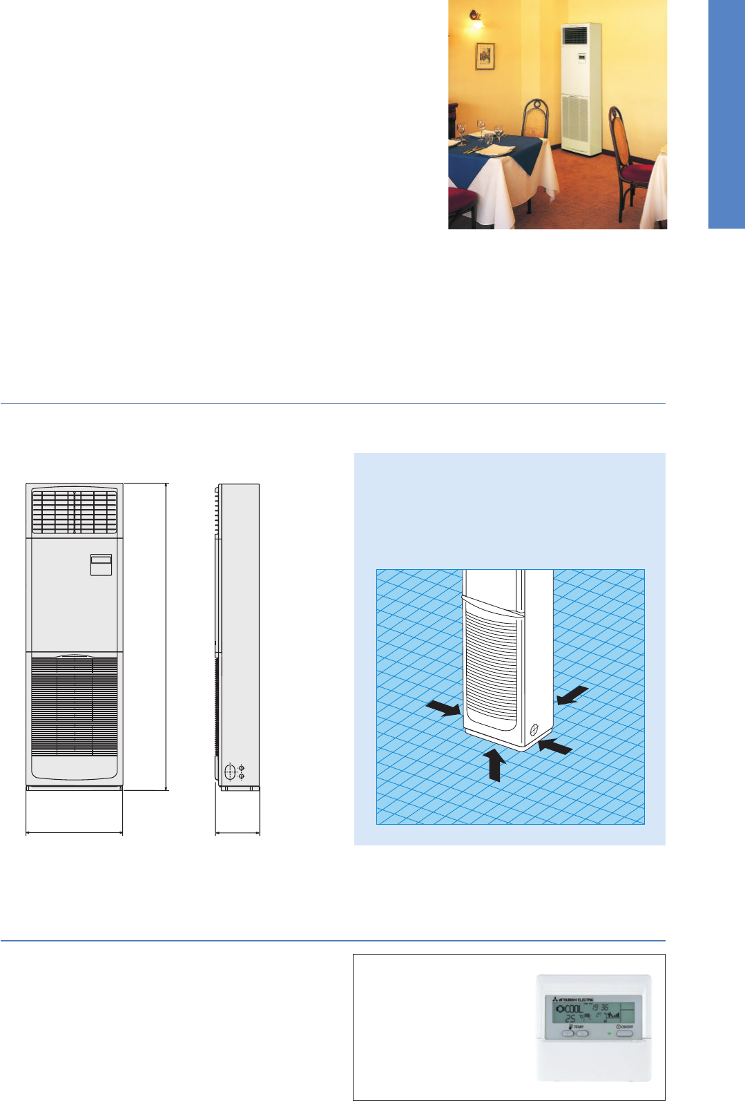
84
PSA
SERIES
Installation of this floor-standing series is easy and quick.
An excellent choice when there is a sudden need for an air conditioner to be installed.
Quick and Easy Installation, Space-saving and
Design That Compliments Any Interior
The floor-standing indoor unit is mounted on the floor, enabling quick installation. Its compact body requires only minimal space.
Built-in Remote Controller
Easy Operation with Built-in PAR-21MAA Remote Controller
Icon, letter and number visibility are improved with the adoption of
a dot liquid-crystal display (LCD), and operation management func-
tions have been increased.
4-way pipe work connections enable greater freedom
in installation
Remarkable freedom in choosing installation sites is allowed
by providing piping connection to the indoor unit in four
places: left side, back, from underneath and on the right side
of the unit. Even installation in the corner of a room is easy.
• Multi-language Display
• Limited Temperature Range Setting
• Auto-off Timer
•Operation Lock
•Weekly Timer
PSZ-RP KA Indoor Unit Combinations
Indoor unit combinations shown below are possible.
Indoor Unit Combination
Power Inverter (PUHZ-ZRP)
Distribution Pipe
Standard Inverter (PUHZ-P )
Distribution Pipe
For Single
35
–
–
–
–
–
–
–
–
–
–
–
–
71x1
–
–
–
100x1
–
100x1
–
125x1
–
125x1
–
140x1
–
140x1
–
–
–
–
–
–
–
–
–
–
–
–
–
–
–
–
–
–
–
–
–
71x2
MSDD-50TR-E
71x2
MSDD-50TR-E
100x2
100x2
MSDD-50WR-E
125x2
MSDD-50WR-E
125x2
–
–
–
–
–
–
–
–
–
–
–
–
71x3
MSDT-111R-E
71x3
MSDT-111R-E
–
–
–
–
For Twin For Tr iple
For Quadruple
Outdoor Unit Capacity
50 60 71 100125 140200 25071100 125140 200250 140200 250200 250
Main Functions
360mm
600mm
1,900mm
PUHZ-P125/140
PUHZ-P200/250
PUHZ-P100
PUHZ-ZRP100/125/140
PUHZ-ZRP140/200/250
PSA-RP71/100/125/140KA
PSA-RP71/100/125/140KA
PUHZ-ZRP71
●
PSA-RP71KA
Left side
Back
Right side
Underneath
Joint Lap
71
Vector Sine Wave
DC Fan Motor
100-250
DC Scroll
PUHZ-P140
SERIES SELECTION
Indoor Unit Outdoor Unit
Remote Controller
Power Inverter Series
Indoor Unit
Remote Controller
Standard Inverter Series
Outdoor Unit
For Single
For Multi (Twin/Triple)
For Single
For Multi (Twin/Triple)
Built-in
Built-in
71-140
Grooved Piping
Vector-Wave
71
Heat Caulking
Fixing Method
100-140
Grooved Piping
Vector-Wave
Vector Sine Wave DC Rotary
100-140
DC Fan Motor
200/250
DC Scroll
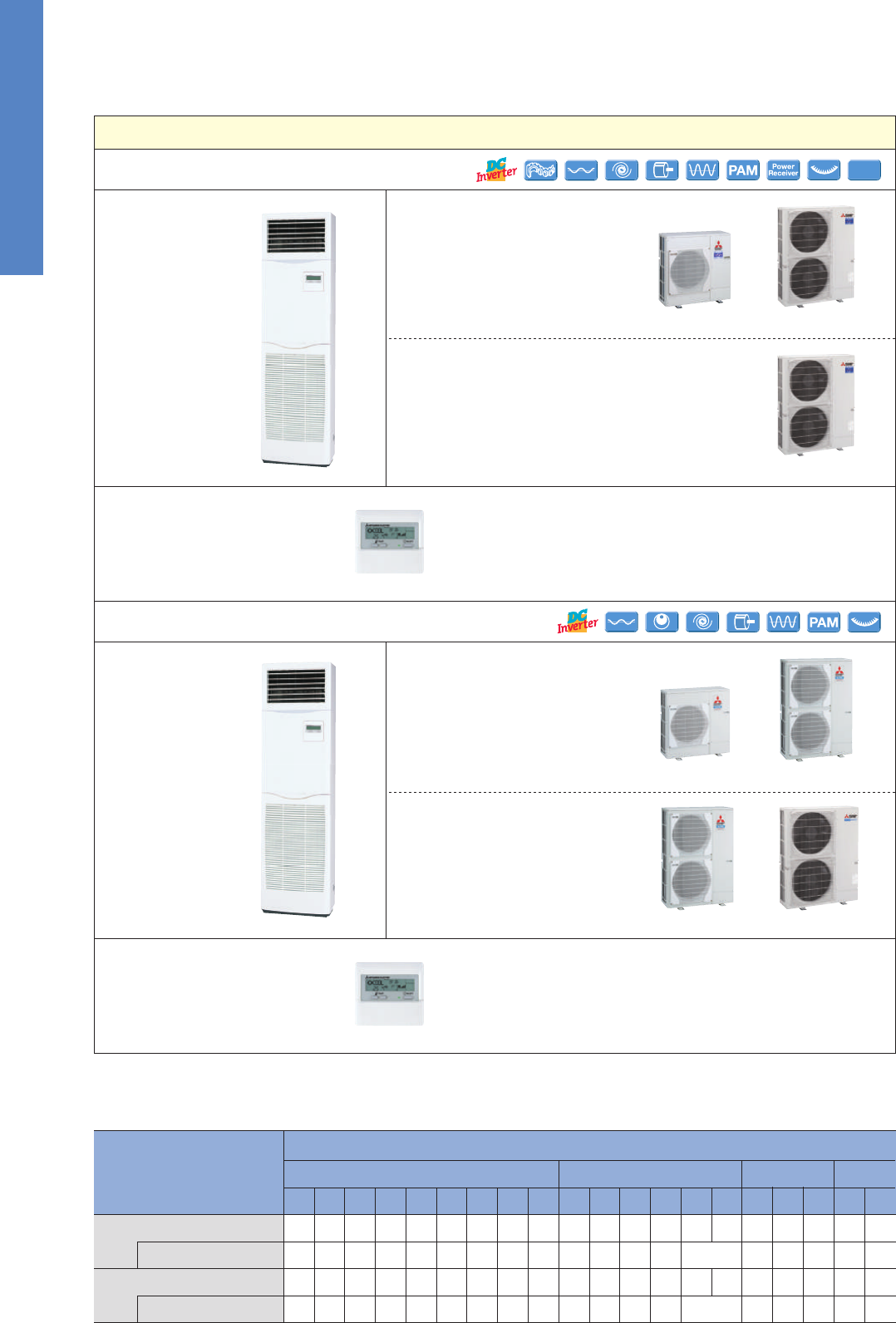
85
PSA
SERIES
Installation of this floor-standing series is easy and quick.
An excellent choice when there is a sudden need for an air conditioner to be installed.
Quick and Easy Installation, Space-saving and
Design That Compliments Any Interior
The floor-standing indoor unit is mounted on the floor, enabling quick installation. Its compact body requires only minimal space.
Built-in Remote Controller
Easy Operation with Built-in PAR-21MAA Remote Controller
Icon, letter and number visibility are improved with the adoption of
a dot liquid-crystal display (LCD), and operation management func-
tions have been increased.
4-way pipe work connections enable greater freedom
in installation
Remarkable freedom in choosing installation sites is allowed
by providing piping connection to the indoor unit in four
places: left side, back, from underneath and on the right side
of the unit. Even installation in the corner of a room is easy.
• Multi-language Display
• Limited Temperature Range Setting
• Auto-off Timer
•Operation Lock
•Weekly Timer
PSZ-RP KA Indoor Unit Combinations
Indoor unit combinations shown below are possible.
Indoor Unit Combination
Power Inverter (PUHZ-ZRP)
Distribution Pipe
Standard Inverter (PUHZ-P )
Distribution Pipe
For Single
35
–
–
–
–
–
–
–
–
–
–
–
–
71x1
–
–
–
100x1
–
100x1
–
125x1
–
125x1
–
140x1
–
140x1
–
–
–
–
–
–
–
–
–
–
–
–
–
–
–
–
–
–
–
–
–
71x2
MSDD-50TR-E
71x2
MSDD-50TR-E
100x2
100x2
MSDD-50WR-E
125x2
MSDD-50WR-E
125x2
–
–
–
–
–
–
–
–
–
–
–
–
71x3
MSDT-111R-E
71x3
MSDT-111R-E
–
–
–
–
For Twin For Tr iple
For Quadruple
Outdoor Unit Capacity
50 60 71 100125 140200 25071100 125140 200250 140200 250200 250
Main Functions
360mm
600mm
1,900mm
PUHZ-P125/140
PUHZ-P200/250
PUHZ-P100
PUHZ-ZRP100/125/140
PUHZ-ZRP140/200/250
PSA-RP71/100/125/140KA
PSA-RP71/100/125/140KA
PUHZ-ZRP71
●
PSA-RP71KA
Left side
Back
Right side
Underneath
Joint Lap
71
Vector Sine Wave
DC Fan Motor
100-250
DC Scroll
PUHZ-P140
SERIES SELECTION
Indoor Unit Outdoor Unit
Remote Controller
Power Inverter Series
Indoor Unit
Remote Controller
Standard Inverter Series
Outdoor Unit
For Single
For Multi (Twin/Triple)
For Single
For Multi (Twin/Triple)
Built-in
Built-in
71-140
Grooved Piping
Vector-Wave
71
Heat Caulking
Fixing Method
100-140
Grooved Piping
Vector-Wave
Vector Sine Wave DC Rotary
100-140
DC Fan Motor
200/250
DC Scroll
86
Inverter Heat Pump
Source
kW 7.1
3.3 - 8.1
1.89
–
–
7.1
396
6.3
A
++
7.6
3.5 - 10.2
2.21
–
–
4.7
4.7 (–10°C)
4.7 (–10°C)
3.5 (–20°C)
0
1666
4.0
A
+
19.4
0.06
0.4
46
20 - 22 - 24
40 - 42 - 44
60
943 - 950 - 330 (+30)
67
55.0
55.0
47
48
67
19.0
25
9.52 / 15.88
50
30
–15 ~ +46
–20 ~ +21
9.5
4.9 - 11.4
2.50
–
–
9.5
595
5.6
A
+
11.2
4.5 - 14.0
3.08
–
–
7.8
7.8 (–10°C)
7.8 (–10°C)
5.8 (–20°C)
0
2761
4.0
A
+
27.2
0.11
0.71
46
25 - 28 - 30
45 - 49 - 51
65
116
110.0
110.0
49
51
69
26.5
32
9.52 / 15.88
75
30
–15 ~ +46
–20 ~ +21
9.5
4.9 - 11.4
2.50
–
–
9.5
606
5.5
A
11.2
4.5 - 14.0
3.08
–
–
7.8
7.8 (–10°C)
7.8 (–10°C)
5.8 (–20°C)
0
2761
4.0
A
+
8.7
0.11
0.71
46
25 - 28 - 30
45 - 49 - 51
65
123
110.0
110.0
49
51
69
8.0
16
9.52 / 15.88
75
30
–15 ~ +46
–20 ~ +21
12.5
5.5 - 14.0
4.09
3.06
–
12.5
847
5.0
*
4
–
14.0
5.0 - 16.0
4.24
3.30
–
9.3
9.3 (–10°C)
9.3 (–10°C)
7.0 (–20°C)
0
3285
4.0
*
4
–
27.2
0.11
0.73
1900 - 600 - 360
46
25 - 28 - 31
45 - 49 - 51
66
116
120.0
120.0
50
52
70
26.5
32
9.52 / 15.88
75
30
–15 ~ +46
–20 ~ +21
12.5
5.5 - 14.0
4.09
3.06
–
12.5
885
4.9
*
4
–
14.0
5.0 - 16.0
4.24
3.30
–
9.3
9.3 (–10°C)
9.3 (–10°C)
7.0 (–20°C)
0
3285
4.0
*
4
–
10.2
0.11
0.73
46
25 - 28 - 31
45 - 49 - 51
66
125
120.0
120.0
50
52
70
9.5
16
9.52 / 15.88
75
30
–15 ~ +46
–20 ~ +21
13.4
6.2 - 15.0
4.06
3.30
–
13.4
872
5.3
*
4
–
16.0
5.7 - 18.0
4.79
3.34
–
10.6
10.6 (–10°C)
10.6 (–10°C)
7.9 (–20°C)
0
3331
4.4
*
4
–
28.7
0.11
0.73
48
25 - 28 - 31
45 - 49 - 51
66
118
120.0
120.0
50
52
70
28.0
40
9.52 / 15.88
75
30
–15 ~ +46
–20 ~ +21
13.4
6.2 - 15.0
4.06
3.30
–
13.4
883
5.3
*
4
–
16.0
5.7 - 18.0
4.79
3.34
–
10.6
10.6 (–10°C)
10.6 (–10°C)
7.9 (–20°C)
0
3331
4.4
*
4
–
13.7
0.11
0.73
48
25 - 28 - 31
45 - 49 - 51
66
131
120.0
120.0
50
52
70
13.0
16
9.52 / 15.88
75
30
–15 ~ +46
–20 ~ +21
Outdoor power supply
VKA
•
VHA:230 / Single / 50, YKA:400 / Three / 50
R410A*
1
PSA-RP71KA
PUHZ-ZRP71VHA
PSA-RP100KA
PUHZ-ZRP100VKA2 PUHZ-ZRP100YKA2
PSA-RP125KA
PUHZ-ZRP125VKA2 PUHZ-ZRP125YKA2
PSA-RP140KA
PUHZ-ZRP140VKA2 PUHZ-ZRP140YKA2
Type
Outdoor (V/Phase/Hz)
Power
Supply
Capacity
Total Input
Rated
Cooling
Heating
(Average
Season)
Operating Current (max)
Indoor
Unit
Outdoor
Unit
Indoor Unit
Outdoor Unit
Refrigerant
kW
Min - Max
kW
kW
kWh/a
Rated
Rated
EEL Rank
EER
Design Load
kW
Min - Max
kW
Rated
kW
kW
A
Capacity
Total Input
COP
Design Load
kW
kW
kW
kW
kWh/a
kW
Declared Capacity
Back Up Heating Capacity
Annual Electricity Consumption
*
2
SCOP
Input Rated
A
Operating Current (max)
mm
Dimensions <Panel>
kg
Weight <Panel>
kg
Weight
m
3
/min
Air Volume [Lo-Mid-Hi]
dB(A)
Sound Level (SPL) [Lo-Mid-Hi]
dB(A)
Sound Level (PWL)
H × W × D
mm
Dimensions H × W × D
Ext.
Piping
mm
Diameter Liquid / Gas
Guaranteed Operating Range
[Outdoor]
°C
Cooling
*
3
°C
Heating
m
Max. Length Out-In
m
Max. Height Out-In
m
3
/min
Air Volume Cooling
m
3
/min
Heating
dB(A)
dB(A)
dB(A)
Sound Level (SPL)
Cooling
Sound Level (PWL)
Cooling
A
Operating Current (max)
A
Breaker Size
Heating
EEL Rank
at reference design temperature
at bivalent temperature
at operation limit temperature
Energy Efficiency Class
Energy Efficiency Class
SEER
Annual Electricity Consumption
*
2
*1 Refrigerant leakage contributes to climate change. Refrigerant with lower global warming potential (GWP) would contribute less to global warming than a refrigerant with higher GWP, if leaked to the atmosphere. This appliance
contains a refrigerant fluid with a GWP equal to 1975. This means that if 1kg of this refrigerant fluid would be leaked to the atmosphere, the impact on global warming would be 1975 times higher than 1kg of CO2, over a period
of 100 years. Never try to interfere with the refrigerant circuit yourself or disassemble the product yourself and always ask a professional.
*2 Energy consumption based on standard test results. Actual energy consumption will depend on how the appliance is used and where it is located.
*3 Optional air protection guide is required where ambient temperature is lower than –5°C. *4 SEER/SCOP values are measured based on EN14825. These values are reference purpose only.
Inverter Heat Pump
Source
kW 9.4
4.9 - 11.2
3.120
–
–
9.4
716
4.6
B
11.2
4.5 - 12.5
3.280
–
–
8.0
6.3 (–10°C)
7.1 (–7°C)
5.0 (–15°C)
1.7
2945
3.8
A
28.7
0.11
0.71
46
25 - 28 - 30
45 - 49 - 51
65
75
60.0
60.0
50
54
70
28.0
32
9.52 / 15.88
50
30
–15 ~ +46
–15 ~ +21
9.4
4.9 - 11.2
3.120
–
–
9.4
716
4.6
B
11.2
4.5 - 12.5
3.280
–
–
8.0
6.3 (–10°C)
7.1 (–7°C)
5.0 (–15°C)
1.7
2945
3.8
A
13.7
0.11
0.71
46
25 - 28 - 30
45 - 49 - 51
65
77
60.0
60.0
50
54
70
13.0
16
9.52 / 15.88
50
30
–15 ~ +46
–15 ~ +21
943 - 950 - 330 (+30) 1350-950 - 330 (+30)
12.3
5.5 - 14.0
4.380
2.81
C
–
–
–
–
14.0
5.0 - 16.0
4.980
2.81
D
–
–
–
–
–
–
–
–
28.7
0.11
0.73
46
25 - 28 - 31
45 - 49 - 51
66
99
100.0
100.0
51
55
71
28.0
32
9.52 / 15.88
50
30
–15 ~ +46
–15 ~ +21
12.3
5.5 - 14.0
4.380
2.81
C
–
–
–
–
14.0
5.0 - 16.0
4.980
2.81
D
–
–
–
–
–
–
–
–
13.7
0.11
0.73
46
25 - 28 - 31
45 - 49 - 51
66
101
100.0
100.0
51
55
71
13.0
16
9.52 / 15.88
50
30
–15 ~ +46
–15 ~ +21
13.6
5.5 - 15.0
5.640
2.41
E
–
–
–
–
16.0
5.0 - 18.0
5.690
2.81
D
–
–
–
–
–
–
–
–
30.2
0.11
0.73
48
25 - 28 - 31
45 - 49 - 51
66
99
100.0
100.0
52
56
73
29.5
40
9.52 / 15.88
50
30
–15 ~ +46
–15 ~ +21
13.6
5.5 - 15.0
5.640
2.41
E
–
–
–
–
16.0
5.0 - 18.0
5.690
2.81
D
–
–
–
–
–
–
–
–
13.7
0.11
0.73
48
25 - 28 - 31
45 - 49 - 51
66
101
100.0
100.0
52
56
73
13.0
16
9.52 / 15.88
50
30
–15 ~ +46
–15 ~ +21
Outdoor power supply
VHA3
•
VHA4:230 / Single / 50, YHA
•
YHA2:400 / Three / 50
R410A*
1
PSA-RP100KA PSA-RP100KA PSA-RP125KA PSA-RP125KA PSA-RP140KA PSA-RP140KA
PUHZ-P100VHA4 PUHZ-P100YHA2 PUHZ-P125VHA3 PUHZ-P125YHAPUHZ-P140VHA3 PUHZ-P140YHA
Type
Outdoor (V/Phase/Hz)
Power
Supply
Capacity
Total Input
Rated
Cooling
Heating
(Average
Season)
Operating Current (max)
Indoor
Unit
Outdoor
Unit
Indoor Unit
Outdoor Unit
Refrigerant
kW
Min - Max
kW
kW
kWh/a
Rated
Rated
EEL Rank
EER
Design Load
kW
Min - Max
kW
Rated
kW
kW
A
Capacity
Total Input
COP
Design Load
kW
kW
kW
kW
kWh/a
kW
Declared Capacity
Back Up Heating Capacity
Annual Electricity Consumption
*
2
SCOP
Input Rated
A
Operating Current (max)
mm
Dimensions <Panel>
kg
Weight <Panel>
kg
Weight
m
3
/min
Air Volume [Lo-Mid-Hi]
dB(A)
Sound Level (SPL) [Lo-Mid-Hi]
dB(A)
Sound Level (PWL)
H × W × D
mm
Dimensions H × W × D
Ext.
Piping
mm
Diameter Liquid / Gas
Guaranteed Operating Range
[Outdoor]
°C
Cooling
*
3
°C
Heating
m
Max. Length Out-In
m
Max. Height Out-In
m
3
/min
Air Volume Cooling
m
3
/min
Heating
dB(A)
dB(A)
dB(A)
Sound Level (SPL)
Cooling
Sound Level (PWL)
Cooling
A
Operating Current (max)
A
Breaker Size
Heating
EEL Rank
at reference design temperature
at bivalent temperature
at operation limit temperature
Energy Efficiency Class
Energy Efficiency Class
SEER
Annual Electricity Consumption
*
2
*1 Refrigerant leakage contributes to climate change. Refrigerant with lower global warming potential (GWP) would contribute less to global warming than a refrigerant with higher GWP, if leaked to the atmosphere. This appliance
contains a refrigerant fluid with a GWP equal to 1975. This means that if 1kg of this refrigerant fluid would be leaked to the atmosphere, the impact on global warming would be 1975 times higher than 1kg of CO2, over a period
of 100 years. Never try to interfere with the refrigerant circuit yourself or disassemble the product yourself and always ask a professional.
*2 Energy consumption based on standard test results. Actual energy consumption will depend on how the appliance is used and where it is located.
*3 Optional air protection guide is required where ambient temperature is lower than –5°C. *4 SEER/SCOP values are measured based on EN14825. These values are reference purpose only.
1338-1050-330(+40)
1900 - 600 - 360
Optional
71-140V
Optional
Optional
Optional Optional
Wi-Fi
Interface
Optional
Optional
Optional Optional
PEAD
SERIES
The thin, ceiling-concealed indoor units of this series are the perfect answer for the air
conditioning needs of buildings with minimum ceiling installation space and wide-
ranging external static pressure. Energy-saving efficiency has been improved, reduc-
ing electricity consumption and contributing to a further reduction in operating cost.
Compact Indoor Units
The height of the models from 35–140 has been unified to 250mm. Compared to the previous PEAD-RP EA model, the height has been reduced
by as much as 75mm (models 100–140), making installation in low ceilings with minimal clearance space possible.
External Static Pressure
■ External static pressure setting
Series
PEAD-RP EA
PEAD-RP GA
PEAD-RP JA
35 50 60 71 100125 140
30/70Pa70/130 (with optional motor) Pa
10/50/70Pa
–– ––
35/50/70/100/150Pa
External static pressure conversion can be set up to five stages. Capable of being set to a maximum of 150Pa, units are applicable to a wide range
of building types.
Drain Pump Option Available with All Models
The line-up consists of two types, models with or without a built-in drain pump.
PEAD-RP35/50/60/71/100/125/140JA(L)Q
Reduction of
75mm
(models 100 –140)
compared to PEAD-EA
PEAD-RP JA(L)Q
250mm
PEAD-RP JAQ Drain pump built-in PEAD-RP JALQ No drain pump
✽
Units with an “L” included at the end of the model name are not equipped with a drain pump.
✽
For products with capacity over 10.0kW, SEER/SCOP values are measured based on EN14825. These values are for reference purposes only.
ErP Lot 10-compliant, Achieving High Energy Efficiency of SEER/SCOP Rank A
+
and A
++
A direct-current (DC) fan motor is installed in the indoor unit, increasing the seasonal energy efficiency of the newly designed Power Inverter Series
(PUHZ-ZRP) and resulting in compliance of the full-capacity models with ErP Lot 10 and energy rankings of A
+
/A
++
for cooling and A/A
+
for heating.
This contributes to an impressive reduction in the cost of annual electricity.
PEAD-RP35JALQ
PUHZ-ZRP35VKA
PEAD-RP50JALQ
PUHZ-ZRP50VKA
PEAD-RP60JALQ
PUHZ-ZRP60VHA
PEAD-RP71JALQ
PUHZ-ZRP71VHA
PEAD-RP100JALQ
PUHZ-ZRP100VKA2
PEAD-RP100JALQ
PUHZ-ZRP100YKA2
PEAD-RP125JALQ
PUHZ-ZRP125VKA2
PEAD-RP125JALQ
PUHZ-ZRP125YKA2
PEAD-RP140JALQ
PUHZ-ZRP140VKA2
PEAD-RP140JALQ
PUHZ-ZRP140YKA2
Cooling
Heating
6.0
4.0
SEER
A
+
SCOP
A
+
5.8
4.3
SEER
A
+
SCOP
A
+
6.1
4.1
SEER
A
++
SCOP
A
+
5.7
3.9
SEER
A
+
SCOP
A
5.7
4.2
SEER
A
+
SCOP
A
+
5.6
4.2
SEER
A
+
SCOP
A
+
5.1
3.9
5.0
3.9
4.9
4.0
4.8
4.0
Wi-Fi
Interface
Minimum SCOP 3.8
Minimum SEER 4.6
Optional
POWER INVERTER
PSZ-RP SERIES
STANDARD INVERTER
PSZ-P SERIES

87
SERIES
SELECTION
Choose from seven types of indoor units and twelve outdoor units that can run up to six indoor units each.
Create the system that best matches room shapes and number of rooms.
MULTI
SPLIT
SELECT INDOOR UNITS
Select the indoor unit to be installed in each room.
Wall-mounted Floor-standing Cassette Ceiling-suspended
Ceiling-concealed
SELECT OUTDOOR UNITS
Select the best outdoor unit based on the number of indoor units and overall system capacity required.
2-port
Connect up to 2 indoor units
3-port
Connect up to 3 indoor units
4-port
Connect up to 4 indoor units
5-port
Connect up to 5 indoor units
6-port
Connect up to 6 indoor units
4-port
Connect up to 4 indoor units
CHECK SYSTEM COMPATIBILITY
Possible combinations depends on the outdoor unit chosen. Please check the following points.
Refer to the “Indoor Unit Compatibility Table” to check if the indoor units selected can be used with
the outdoor unit selected. (Indoor units not listed in the table cannot be used.)
Refer to the “Combination Table” to check if the capacity combination of the indoor unit selected
is connectable. (Combinations not listed cannot be connected.)
Check Indoor Unit Capacity
Combination
If the desired combination cannot be found, please change either the indoor or outdoor unit
to match one of the combinations shown in the tables.
Check Indoor Units
MXZ-5E102VA MXZ-6D122VA
MXZ-4E72VA MXZ-4E83VA
STEP 1
STEP 2
STEP 3
MXZ-4E83VAHZ
2-port
Connect up to 2 indoor units
MXZ-2E53VAHZ
MSZ-FH
MSZ-EF
MSZ-SF (15
•
20)
MSZ-GF
MSZ-SF (25-50)
MFZ-KJ
SLZ-KF
PLA
MLZ-KA
PCA
SEZ-KD
PEAD
HYPER HEATING*
*Refer to page101 and page 109 for detailed information.
MXZ-2D33VA(2)
MXZ-2D42VA(2)
MXZ-2D53VA(H)
MXZ-3E54VA
MXZ-3E68VA
88
SERIES
SELECTION
Choose from seven types of indoor units and twelve outdoor units that can run up to six indoor units each.
Create the system that best matches room shapes and number of rooms.
MULTI
SPLIT
SELECT INDOOR UNITS
Select the indoor unit to be installed in each room.
Wall-mounted Floor-standing Cassette Ceiling-suspended
Ceiling-concealed
SELECT OUTDOOR UNITS
Select the best outdoor unit based on the number of indoor units and overall system capacity required.
2-port
Connect up to 2 indoor units
3-port
Connect up to 3 indoor units
4-port
Connect up to 4 indoor units
5-port
Connect up to 5 indoor units
6-port
Connect up to 6 indoor units
4-port
Connect up to 4 indoor units
CHECK SYSTEM COMPATIBILITY
Possible combinations depends on the outdoor unit chosen. Please check the following points.
Refer to the “Indoor Unit Compatibility Table” to check if the indoor units selected can be used with
the outdoor unit selected. (Indoor units not listed in the table cannot be used.)
Refer to the “Combination Table” to check if the capacity combination of the indoor unit selected
is connectable. (Combinations not listed cannot be connected.)
Check Indoor Unit Capacity
Combination
If the desired combination cannot be found, please change either the indoor or outdoor unit
to match one of the combinations shown in the tables.
Check Indoor Units
MXZ-5E102VA MXZ-6D122VA
MXZ-4E72VA MXZ-4E83VA
STEP 1
STEP 2
STEP 3
MXZ-4E83VAHZ
2-port
Connect up to 2 indoor units
MXZ-2E53VAHZ
MSZ-FH
MSZ-EF
MSZ-SF (15
•
20)
MSZ-GF
MSZ-SF (25-50)
MFZ-KJ
SLZ-KF
PLA
MLZ-KA
PCA
SEZ-KD
PEAD
HYPER HEATING*
*Refer to page101 and page 109 for detailed information.
MXZ-2D33VA(2)
MXZ-2D42VA(2)
MXZ-2D53VA(H)
MXZ-3E54VA
MXZ-3E68VA
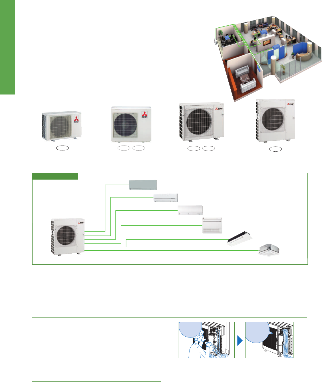
89
MXZ
SERIES
Advancements in the MXZ Series include eciency and exibility in system expansion
capabilities. The best solution when requiring multi-system air conditioning needs.
Outdoor
Unit
EXAMPLE SYSTEM
Handle Up to 6 Rooms with a Single Outdoor Unit
Wiring/Piping Correction Function* (3D54/3D68/4D72/4E83/5E102/6D122)
Support Functions
The MXZ Series oers a ten-system line-up to choose from, ranging between 3.3 and 12.2kW. All of them are compatible with specic
M, S and P series indoor units. A single outdoor unit can handle a wide range of building layouts.
2-port
3-port
4-port
4-port 5-port
6-port
MXZ-2D33VA(2)
MXZ-2D42VA(2)
MXZ-2D53VA (H)
MXZ-4E83VA
MXZ-5E102VA
MXZ-3E54VA
MXZ-3E68VA
MXZ-4E72VA
MXZ-6D122VA
MXZ-6D122VA system
Simply press a single button to conrm if wiring and piping are properly
connected. Wiring errors are corrected automatically when discovered.
This eliminates the need to conrm complicated wiring connections
when expanding the system. (For details, refer to the outdoor unit instal-
lation manual.)
*Function cannot be used when the outdoor temperature is below 0°C.
The correction process requires 10–20 minutes to complete and must be conducted with
the unit set to the “Cooling” mode.
Ampere Limit Adjustment*
(4E83/5E102/6D122)
Dipswitch settings can be used to adjust the maximum electrical current
for operation. This function is highly recommended for managing energy
costs. (For details, refer to the outdoor unit installation manual.)
*Maximum capacity is lowered with the use of this function.
Operation Lock
To accommodate specic use applications, cooling or heating operation
can be specied when setting the control board of the outdoor unit. A
convenient option when a system needs to be congured for exclusive
cooling or heating service. (For details, refer to the outdoor unit installa-
tion manual.)
Wiring
confirmation
is time
consuming.
The outdoor unit
matches
pipes and wiring.
MXZ-6D122VA
2D-4E83
Up to 2 Indoor Units
Cooling
Heating
(Average
Season)
Max. Operating Current (Indoor+Outdoor)
Outdoor
Unit
Ext.
Piping
Guaranteed Operating Range
[Outdoor]
Source
Outdoor (V/Phase/Hz)
Capacity
Input
(Indoor+Outdoor)
Design Load
Annual Electricity Consumption*
2
SEER*
4
Capacity
Input
(Indoor+Outdoor)
Design Load
Declared
Capacity
Back Up Heating Capacity
Annual Electricity Consumption*
2
SCOP*
4
Dimensions
Weight
Air Volume
Sound Level (SPL)
Sound Level (PWL)
Breaker Size
Diameter
Total Piping Length (max)
Each Indoor Unit Piping Length (max)
Rated
Min - Max
Rated
Energy Eciency Class
*
4
Rated
Min - Max
Rated
at reference design temperature
at bivalent temperature
at operation limit temperature
Energy Eciency Class
*
4
H × W × D 550 - 800 (+69) - 285 (+59.5) 710 - 840 (+30) - 330 (+66) 796 - 950 - 330
Cooling
Heating
Cooling
Cooling
Heating
Liquid
Cooling
Heating
kW
kW
kW
kW
kWh/a
kW
kW
kW
kW
kW
kW
kW
kW
kWh/a
A
mm
kg
m
3
/min
m
3
/min
dB(A)
dB(A)
dB(A)
A
mm
Gas
mm
m
m
Max. Height
m
Chargeless Length
m
o
C
o
C
R410A*
1
Outdoor power supply
230 / Single / 50
Please refer to (*4)
N:
MXZ-2D33VA(2)
N:
MXZ-2D42VA(2)
N:
MXZ-2D53VA
N:
MXZ-2D53VAH
N:
MXZ-3E54VA2
N:
MXZ-3E68VA
N:
MXZ-4E72VA MXZ-4E83VA MXZ-5E102VA
Type (Inverter Multi - Split Heat Pump)
Indoor Unit
Outdoor Unit
Refrigerant
Power
Supply
3.3
1.1 - 3.8
0.90
3.3
211
5.5
A
4.0
1.0 - 4.1
0.96
2.7
2.1
2.4
1.7
0.6
926
4.1
A
+
10.0
32
32.9
33.7
49
50
63
10
6.35 × 2
9.52 × 2
20
15
10
20
–10 ~ +46
–15 ~ +24
4.2
1.1 - 4.4
1.00
4.2
219
6.7
A
++
4.5
1.0 - 4.8
0.93
3.2
2.7
3.0
2.3
0.5
1065
4.2
A
+
12.2
37
27.7
33.3
46
51
60
15
6.35 × 2
9.52 × 2
30
20
15 (10)*
3
20
–10 ~ +46
–15 ~ +24
5.3
1.1 - 5.6
1.54
5.3
262
7.1
A
++
6.4
1.0 - 7.0
1.70
4.5
3.7
4.0
3.3
0.8
1507
4.2
A
+
12.2
37
32.9
33.3
50
53
64
15
6.35 × 2
9.52 × 2
30
20
15 (10)*
3
20
–10 ~ +46
–15 ~ +24
5.3
1.1 - 5.6
1.54
5.3
262
7.1
A
++
6.4
1.0 - 7.0
1.70
4.5
3.6
4.0
3.0
0.9
1546
4.1
A
+
12.2
38
32.9
33.3
50
53
64
15
6.35 × 2
9.52 × 2
30
20
15 (10)*
3
20
–10 ~ +46
–20 ~ +24
5.4
2.9 - 6.8
1.35
5.4
295
6.4
A
++
7.0
2.6 - 9.0
1.59
5.0
4.00
4.49
3.17
1.00
1751
4.0
A
+
18.0
58
42.1
43.0
50
53
64
25
6.35 × 3
9.52 × 3
50
25
15 (10)*
3
40
–10 ~ +46
–15 ~ +24
6.8
2.9 - 8.4
2.19
6.8
425
5.6
A
+
8.6
2.6 - 10.6
2.38
6.8
5.4
6.0
4.4
1.4
2466
3.9
A
18.0
58
42.1
43.0
50
53
64
25
6.35 × 3
9.52 × 3
60
25
15 (10)*
3
40
–10 ~ +46
–15 ~ +24
7.2
3.7 - 8.8
2.25
7.2
443
5.7
A
+
8.6
3.4 - 10.7
2.28
7.0
5.6
6.2
4.7
1.4
2516
3.9
A
18.0
59
42.1
43.0
50
53
64
25
6.35 × 4
12.7×1+9.52×3
60
25
15 (10)*
3
40
–10 ~ +46
–15 ~ +24
8.3
3.7 - 9.2
2.44
8.3
460
6.3
A
++
9.3
3.4 - 11.6
2.00
8.7
7.1
7.8
6.0
1.6
2884
4.2
A
+
21.4
62
55.6
55.6
49
51
61
25
6.35 × 4
12.7×1+9.52×3
70
25
15 (10)*
3
25
–10 ~ +46
–15 ~ +24
10.2
3.9 - 11.0
3.15
10.2
537
6.6
A
++
10.5
4.1 - 14.0
2.34
8.9
7.3
7.9
6.3
1.6
2958
4.2
A
+
21.4
63
65.1
68.0
52
56
65
25
6.35 × 5
12.7×1+9.52×4
80
25
15 (10)*
3
0
–10 ~ +46
–15 ~ +24
Up to 3 Indoor Units Up to 4 Indoor Units
Up to 5 Indoor Units
Up to 6 Indoor Units
Cooling
Heating
Operating Current (max)*
5
Outdoor
Unit
Ext.
Piping
Guaranteed Operating Range
[Outdoor]
Source
Outdoor (V/Phase/Hz)
Capacity
Input*
5
EER*
6
Capacity
Input*
5
COP*
6
Dimensions
Weight
Air Volume
Sound Level (SPL)
Sound Level (PWL)
Breaker Size
Diameter
Total Piping Length (max)
Each Indoor Unit Piping Length (max)
Rated
Rated
EEL Rank
Rated
Rated
EEL Rank
H × W × D
Cooling
Heating
Cooling
Cooling
Heating
Liquid
Cooling
Heating
kW
kW
Min - Max
kW
kW
Min - Max
kW
kW
A
mm
kg
m
3
/min
m
3
/min
dB(A)
dB(A)
dB(A)
A
mm
Gas
mm
m
m
Max. Height
m
Chargeless Length
m
o
C
o
C
R410A*
1
Outdoor power supply
230 / Single / 50
Please refer to (*5)
MXZ-6D122VA
Type (Inverter Multi - Split Heat Pump)
Indoor Unit
Outdoor Unit
Refrigerant
Power
Supply
12.2
3.5 - 13.5
3.66
3.33
A
14.0
3.5 - 16.5
3.31
4.23
A
26.8
1048-950 -330
88
63.0
77.0
55
57
69
32
6.35 ×6
12.7×1+9.52×5
80
25
15 (10)*
3
30
–10 ~ +46
–15 ~ +24
*1 Refrigerant leakage contributes to climate change. Refrigerant with lower global warming potential (GWP) would contribute less to global warming than a refrigerant with higher GWP, if leaked to the atmosphere. This appliance
contains a refrigerant uid with a GWP equal to 1975. This means that if 1kg of this refrigerant uid would be leaked to the atmosphere, the impact on global warming would be 1975 times higher than 1kg of CO2, over a period of
100 years. Never try to interfere with the refrigerant circuit yourself or disassemble the product yourself and always ask a professional.
*2
Energy consumption based on standard test results. Actual energy consumption will depend on how the appliance is used and where it is located.
*3 If the outdoor unit is installed higher than the indoor unit, max. height is reduced to 10m.
*4 EER/COP, EEL rank, SEER/SCOP values and energy eciency class are measured
when connected to the indoor units listed below.
MXZ-2D33VA MSZ-SF15VA + MSZ-EF18VE
MXZ-2D42VA MSZ-EF18VE2 + MSZ-EF25VE2
MXZ-2D53VA(H) MSZ-EF18VE2 + MSZ-EF35VE2
MXZ-3D54VA2 MSZ-EF18VE2 + MSZ-EF18VE2 + MSZ-EF18VE2
MXZ-3D68VA MSZ-EF18VE2 + MSZ-EF25VE2 + MSZ-EF25VE2
MXZ-4D72VA MSZ-EF18VE2 + MSZ-EF18VE2 + MSZ-EF18VE2 + MSZ-EF18VE2
MXZ-4E83VA MSZ-EF18VE2 + MSZ-EF18VE2 + MSZ-EF22VE2 + MSZ-EF25VE2
MXZ-5E102VA MSZ-EF18VE2 + MSZ-EF18VE2 + MSZ-EF22VE2 + MSZ-EF22VE2 + MSZ-EF22VE2
*5 Power input and operating current (max) gures are for outdoor unit only
*6 EER/COP, EEL rank, values and energy eciency class are measured
when connected to the indoor units listed below.
MXZ-6D122VA MSZ-EF22VE × 6
N: Please refer to the NOTE below.
INVERTER MULTI
MXZ SERIES
Please fill out the requested information
Please fill out the requested information
NOTE
When connecting the MFZ-KJ series indoor unit(s) to this outdoor unit, charge additional refrigerant according to
the instructions in the diagram below.
MXZ-2D33VA
No. of
MFZ-KJ indoor units
Maximum amount
of refrigerant
Pipe length (L)
~20m
100g additional (Total 1250g)
1 unit
2 units
1250g
MXZ-2D42VA MXZ-2D53VA MXZ-2D53VAH
No. of
MFZ-KJ indoor units
Maximum amount
of refrigerant
Pipe length (L)
~20m
100g additional (Total 1400g)
200g additional (Total 1500g)
~30m
100g+{(L-20)m×20g/m)}
200g+{(L-20)m×20g/m)}
1 unit
2 units
1600g
1700g
MXZ-3D54VA2
No. of
MFZ-KJ indoor units
Maximum amount
of refrigerant
Pipe length (L)
~40m
100g additional (Total 2800g)
200g additional (Total 2900g)
300g additional (Total 3000g)
~50m
100g+{(L-40)m×20g/m)}
200g+{(L-40)m×20g/m)}
300g+{(L-40)m×20g/m)}
1 unit
2 units
3 units
3000g
3100g
3200g
MXZ-3D68VA MXZ-4D72VA
No. of
MFZ-KJ indoor units
Maximum amount
of refrigerant
Pipe length (L)
~40m
100g additional (Total 2800g)
200g additional (Total 2900g)
300g additional (Total 3000g)
~60m
100g+{(L-40)m×20g/m)}
200g+{(L-40)m×20g/m)}
300g+{(L-40)m×20g/m)}
1 unit
2 units
3 units
3200g
3300g
3400g
Not available (Only one MFZ-KJ series indoor unit can be connected.)
MSZ-FH
MLZ-KA
MSZ-SF
MSZ-EF
SLZ-KF
MFZ-KJ
4E83-6D 3D-4D72
Number of MFZ-KJ should be one or two when connected to MXZ-4D72VA. If three and more MFZ-KJ are connected,
use other outdoor units, such as MXZ-3D68VA and MXZ-4E83VA.
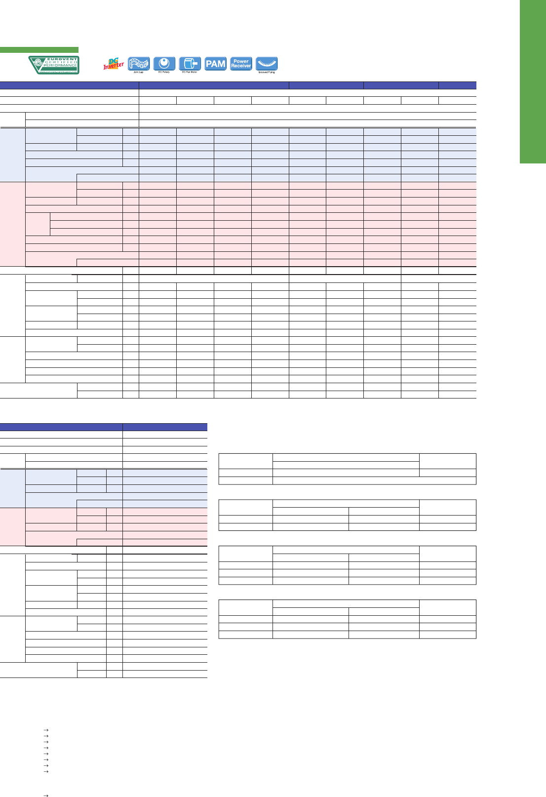
90
MXZ
SERIES
Advancements in the MXZ Series include eciency and exibility in system expansion
capabilities. The best solution when requiring multi-system air conditioning needs.
Outdoor
Unit
EXAMPLE SYSTEM
Handle Up to 6 Rooms with a Single Outdoor Unit
Wiring/Piping Correction Function* (3D54/3D68/4D72/4E83/5E102/6D122)
Support Functions
The MXZ Series oers a ten-system line-up to choose from, ranging between 3.3 and 12.2kW. All of them are compatible with specic
M, S and P series indoor units. A single outdoor unit can handle a wide range of building layouts.
2-port
3-port
4-port
4-port 5-port
6-port
MXZ-2D33VA(2)
MXZ-2D42VA(2)
MXZ-2D53VA (H)
MXZ-4E83VA
MXZ-5E102VA
MXZ-3E54VA
MXZ-3E68VA
MXZ-4E72VA
MXZ-6D122VA
MXZ-6D122VA system
Simply press a single button to conrm if wiring and piping are properly
connected. Wiring errors are corrected automatically when discovered.
This eliminates the need to conrm complicated wiring connections
when expanding the system. (For details, refer to the outdoor unit instal-
lation manual.)
*Function cannot be used when the outdoor temperature is below 0°C.
The correction process requires 10–20 minutes to complete and must be conducted with
the unit set to the “Cooling” mode.
Ampere Limit Adjustment*
(4E83/5E102/6D122)
Dipswitch settings can be used to adjust the maximum electrical current
for operation. This function is highly recommended for managing energy
costs. (For details, refer to the outdoor unit installation manual.)
*Maximum capacity is lowered with the use of this function.
Operation Lock
To accommodate specic use applications, cooling or heating operation
can be specied when setting the control board of the outdoor unit. A
convenient option when a system needs to be congured for exclusive
cooling or heating service. (For details, refer to the outdoor unit installa-
tion manual.)
Wiring
confirmation
is time
consuming.
The outdoor unit
matches
pipes and wiring.
MXZ-6D122VA
2D-4E83
Up to 2 Indoor Units
Cooling
Heating
(Average
Season)
Max. Operating Current (Indoor+Outdoor)
Outdoor
Unit
Ext.
Piping
Guaranteed Operating Range
[Outdoor]
Source
Outdoor (V/Phase/Hz)
Capacity
Input
(Indoor+Outdoor)
Design Load
Annual Electricity Consumption*
2
SEER*
4
Capacity
Input
(Indoor+Outdoor)
Design Load
Declared
Capacity
Back Up Heating Capacity
Annual Electricity Consumption*
2
SCOP*
4
Dimensions
Weight
Air Volume
Sound Level (SPL)
Sound Level (PWL)
Breaker Size
Diameter
Total Piping Length (max)
Each Indoor Unit Piping Length (max)
Rated
Min - Max
Rated
Energy Eciency Class
*
4
Rated
Min - Max
Rated
at reference design temperature
at bivalent temperature
at operation limit temperature
Energy Eciency Class
*
4
H × W × D 550 - 800 (+69) - 285 (+59.5) 710 - 840 (+30) - 330 (+66) 796 - 950 - 330
Cooling
Heating
Cooling
Cooling
Heating
Liquid
Cooling
Heating
kW
kW
kW
kW
kWh/a
kW
kW
kW
kW
kW
kW
kW
kW
kWh/a
A
mm
kg
m
3
/min
m
3
/min
dB(A)
dB(A)
dB(A)
A
mm
Gas
mm
m
m
Max. Height
m
Chargeless Length
m
o
C
o
C
R410A*
1
Outdoor power supply
230 / Single / 50
Please refer to (*4)
N:
MXZ-2D33VA(2)
N:
MXZ-2D42VA(2)
N:
MXZ-2D53VA
N:
MXZ-2D53VAH
N:
MXZ-3E54VA2
N:
MXZ-3E68VA
N:
MXZ-4E72VA MXZ-4E83VA MXZ-5E102VA
Type (Inverter Multi - Split Heat Pump)
Indoor Unit
Outdoor Unit
Refrigerant
Power
Supply
3.3
1.1 - 3.8
0.90
3.3
211
5.5
A
4.0
1.0 - 4.1
0.96
2.7
2.1
2.4
1.7
0.6
926
4.1
A
+
10.0
32
32.9
33.7
49
50
63
10
6.35 × 2
9.52 × 2
20
15
10
20
–10 ~ +46
–15 ~ +24
4.2
1.1 - 4.4
1.00
4.2
219
6.7
A
++
4.5
1.0 - 4.8
0.93
3.2
2.7
3.0
2.3
0.5
1065
4.2
A
+
12.2
37
27.7
33.3
46
51
60
15
6.35 × 2
9.52 × 2
30
20
15 (10)*
3
20
–10 ~ +46
–15 ~ +24
5.3
1.1 - 5.6
1.54
5.3
262
7.1
A
++
6.4
1.0 - 7.0
1.70
4.5
3.7
4.0
3.3
0.8
1507
4.2
A
+
12.2
37
32.9
33.3
50
53
64
15
6.35 × 2
9.52 × 2
30
20
15 (10)*
3
20
–10 ~ +46
–15 ~ +24
5.3
1.1 - 5.6
1.54
5.3
262
7.1
A
++
6.4
1.0 - 7.0
1.70
4.5
3.6
4.0
3.0
0.9
1546
4.1
A
+
12.2
38
32.9
33.3
50
53
64
15
6.35 × 2
9.52 × 2
30
20
15 (10)*
3
20
–10 ~ +46
–20 ~ +24
5.4
2.9 - 6.8
1.35
5.4
295
6.4
A
++
7.0
2.6 - 9.0
1.59
5.0
4.00
4.49
3.17
1.00
1751
4.0
A
+
18.0
58
42.1
43.0
50
53
64
25
6.35 × 3
9.52 × 3
50
25
15 (10)*
3
40
–10 ~ +46
–15 ~ +24
6.8
2.9 - 8.4
2.19
6.8
425
5.6
A
+
8.6
2.6 - 10.6
2.38
6.8
5.4
6.0
4.4
1.4
2466
3.9
A
18.0
58
42.1
43.0
50
53
64
25
6.35 × 3
9.52 × 3
60
25
15 (10)*
3
40
–10 ~ +46
–15 ~ +24
7.2
3.7 - 8.8
2.25
7.2
443
5.7
A
+
8.6
3.4 - 10.7
2.28
7.0
5.6
6.2
4.7
1.4
2516
3.9
A
18.0
59
42.1
43.0
50
53
64
25
6.35 × 4
12.7×1+9.52×3
60
25
15 (10)*
3
40
–10 ~ +46
–15 ~ +24
8.3
3.7 - 9.2
2.44
8.3
460
6.3
A
++
9.3
3.4 - 11.6
2.00
8.7
7.1
7.8
6.0
1.6
2884
4.2
A
+
21.4
62
55.6
55.6
49
51
61
25
6.35 × 4
12.7×1+9.52×3
70
25
15 (10)*
3
25
–10 ~ +46
–15 ~ +24
10.2
3.9 - 11.0
3.15
10.2
537
6.6
A
++
10.5
4.1 - 14.0
2.34
8.9
7.3
7.9
6.3
1.6
2958
4.2
A
+
21.4
63
65.1
68.0
52
56
65
25
6.35 × 5
12.7×1+9.52×4
80
25
15 (10)*
3
0
–10 ~ +46
–15 ~ +24
Up to 3 Indoor Units Up to 4 Indoor Units
Up to 5 Indoor Units
Up to 6 Indoor Units
Cooling
Heating
Operating Current (max)*
5
Outdoor
Unit
Ext.
Piping
Guaranteed Operating Range
[Outdoor]
Source
Outdoor (V/Phase/Hz)
Capacity
Input*
5
EER*
6
Capacity
Input*
5
COP*
6
Dimensions
Weight
Air Volume
Sound Level (SPL)
Sound Level (PWL)
Breaker Size
Diameter
Total Piping Length (max)
Each Indoor Unit Piping Length (max)
Rated
Rated
EEL Rank
Rated
Rated
EEL Rank
H × W × D
Cooling
Heating
Cooling
Cooling
Heating
Liquid
Cooling
Heating
kW
kW
Min - Max
kW
kW
Min - Max
kW
kW
A
mm
kg
m
3
/min
m
3
/min
dB(A)
dB(A)
dB(A)
A
mm
Gas
mm
m
m
Max. Height
m
Chargeless Length
m
o
C
o
C
R410A*
1
Outdoor power supply
230 / Single / 50
Please refer to (*5)
MXZ-6D122VA
Type (Inverter Multi - Split Heat Pump)
Indoor Unit
Outdoor Unit
Refrigerant
Power
Supply
12.2
3.5 - 13.5
3.66
3.33
A
14.0
3.5 - 16.5
3.31
4.23
A
26.8
1048-950 -330
88
63.0
77.0
55
57
69
32
6.35 ×6
12.7×1+9.52×5
80
25
15 (10)*
3
30
–10 ~ +46
–15 ~ +24
*1 Refrigerant leakage contributes to climate change. Refrigerant with lower global warming potential (GWP) would contribute less to global warming than a refrigerant with higher GWP, if leaked to the atmosphere. This appliance
contains a refrigerant uid with a GWP equal to 1975. This means that if 1kg of this refrigerant uid would be leaked to the atmosphere, the impact on global warming would be 1975 times higher than 1kg of CO2, over a period of
100 years. Never try to interfere with the refrigerant circuit yourself or disassemble the product yourself and always ask a professional.
*2
Energy consumption based on standard test results. Actual energy consumption will depend on how the appliance is used and where it is located.
*3 If the outdoor unit is installed higher than the indoor unit, max. height is reduced to 10m.
*4 EER/COP, EEL rank, SEER/SCOP values and energy eciency class are measured
when connected to the indoor units listed below.
MXZ-2D33VA MSZ-SF15VA + MSZ-EF18VE
MXZ-2D42VA MSZ-EF18VE2 + MSZ-EF25VE2
MXZ-2D53VA(H) MSZ-EF18VE2 + MSZ-EF35VE2
MXZ-3D54VA2 MSZ-EF18VE2 + MSZ-EF18VE2 + MSZ-EF18VE2
MXZ-3D68VA MSZ-EF18VE2 + MSZ-EF25VE2 + MSZ-EF25VE2
MXZ-4D72VA MSZ-EF18VE2 + MSZ-EF18VE2 + MSZ-EF18VE2 + MSZ-EF18VE2
MXZ-4E83VA MSZ-EF18VE2 + MSZ-EF18VE2 + MSZ-EF22VE2 + MSZ-EF25VE2
MXZ-5E102VA MSZ-EF18VE2 + MSZ-EF18VE2 + MSZ-EF22VE2 + MSZ-EF22VE2 + MSZ-EF22VE2
*5 Power input and operating current (max) gures are for outdoor unit only
*6 EER/COP, EEL rank, values and energy eciency class are measured
when connected to the indoor units listed below.
MXZ-6D122VA MSZ-EF22VE × 6
N: Please refer to the NOTE below.
INVERTER MULTI
MXZ SERIES
Please fill out the requested information
Please fill out the requested information
NOTE
When connecting the MFZ-KJ series indoor unit(s) to this outdoor unit, charge additional refrigerant according to
the instructions in the diagram below.
MXZ-2D33VA
No. of
MFZ-KJ indoor units
Maximum amount
of refrigerant
Pipe length (L)
~20m
100g additional (Total 1250g)
1 unit
2 units
1250g
MXZ-2D42VA MXZ-2D53VA MXZ-2D53VAH
No. of
MFZ-KJ indoor units
Maximum amount
of refrigerant
Pipe length (L)
~20m
100g additional (Total 1400g)
200g additional (Total 1500g)
~30m
100g+{(L-20)m×20g/m)}
200g+{(L-20)m×20g/m)}
1 unit
2 units
1600g
1700g
MXZ-3D54VA2
No. of
MFZ-KJ indoor units
Maximum amount
of refrigerant
Pipe length (L)
~40m
100g additional (Total 2800g)
200g additional (Total 2900g)
300g additional (Total 3000g)
~50m
100g+{(L-40)m×20g/m)}
200g+{(L-40)m×20g/m)}
300g+{(L-40)m×20g/m)}
1 unit
2 units
3 units
3000g
3100g
3200g
MXZ-3D68VA MXZ-4D72VA
No. of
MFZ-KJ indoor units
Maximum amount
of refrigerant
Pipe length (L)
~40m
100g additional (Total 2800g)
200g additional (Total 2900g)
300g additional (Total 3000g)
~60m
100g+{(L-40)m×20g/m)}
200g+{(L-40)m×20g/m)}
300g+{(L-40)m×20g/m)}
1 unit
2 units
3 units
3200g
3300g
3400g
Not available (Only one MFZ-KJ series indoor unit can be connected.)
MSZ-FH
MLZ-KA
MSZ-SF
MSZ-EF
SLZ-KF
MFZ-KJ
4E83-6D 3D-4D72
Number of MFZ-KJ should be one or two when connected to MXZ-4D72VA. If three and more MFZ-KJ are connected,
use other outdoor units, such as MXZ-3D68VA and MXZ-4E83VA.
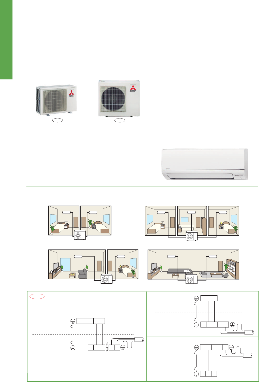
91
MXZ-DM
SERIES
Multi-port outdoor units exclusively for MSZ-HJ and MSZ-DM indoor units.
2-port
3-port
MXZ-2DM40VA
MXZ-3DM50VA
Up to 2 Indoor Units
Cooling
Heating
(Average
Season)
Operating Current (max)
Outdoor
Unit
Ext.
Piping
Guaranteed Operating Range
[Outdoor]
Source
Outdoor (V/Phase/Hz)
Capacity
Input
*
4
EER*
4
SEER*
4
Design Load
Annual Electricity Consumption*
2
Capacity
Input
COP*
4
Declared
Capacity
Design Load
Back Up Heating Capacity
Annual Electricity Consumption*
2
SCOP*
4
Dimensions
Weight
Air Volume
Sound Level (SPL)
Sound Level (PWL)
Breaker Size
Port Diameter
Total Piping Length (max)
Each Indoor Unit Piping Length (max)
Rated
Rated
EEL Rank
*
4
Energy Eciency Class
*
4
Rated
Rated
EEL Rank
*
4
at reference design temperature
at bivalent temperature
at operation limit temperature
Energy Eciency Class
*
4
H × W × D
Cooling
Heating
Cooling
Cooling
Heating
Liquid / Gas
Cooling
Heating
kW
kW
kW
kWh/a
kW
kW
kW
kW
kW
kW
kW
kWh/a
A
mm
kg
m
3
/min
m
3
/min
dB(A)
dB(A)
dB(A)
Operating Current
Cooling
A
Heating
A
A
mm
m
m
Max. Height
m
Chargeless Length
m
o
C
o
C
R410A*
1
Outdoor power supply
230 / Single / 50
Please refer to (*4)
MXZ-2DM40VA MXZ-3DM50VA
Type (Inverter Multi - Split Heat Pump)
Indoor Unit
Outdoor Unit
Refrigerant
Power
Supply
4.0
1.05
3.81
A
4.0
226
6.1
A
++
4.3
1.16
3.71
A
3.2
2.73
3.01
2.27
0.47
1105
4.0
A
+
12.2
550 - 800 (+69) - 285 (+59.5)
32
29.2
27.7
48
52
63
5.1
5.6
15
6.35 × 2 / 9.52 × 2
30
20
15 (10)*
3
20
5.0
1.13
4.42
A
5.0
283
6.1
A
++
6.0
1.31
4.58
A
4.0
3.34
3.73
2.70
0.66
1455
3.8
A
18.0
710 - 840 (+30) - 330 (+66)
57
37.5
39.6
50
53
64
5.0
5.8
25
6.35 × 3 / 9.52 × 3
50
25
15 (10)*
3
40
Up to 3 Indoor Units
*1 Refrigerant leakage contributes to climate change. Refrigerant with lower global warming potential (GWP) would contribute less to global warming than a refrigerant with higher GWP, if leaked to the atmosphere. This appliance
contains a refrigerant uid with a GWP equal to 1975. This means that if 1 kg of this refrigerant uid would be leaked to the atmosphere, the impact on global warming would be 1975 times higher than 1 kg of CO2, over a period of
100 years. Never try to interfere with the refrigerant circuit yourself or disassemble the product yourself and always ask a professional.
*2
Energy consumption based on standard test results.Actual energy consumption will depend on how the appliance is used and where it is located.
*3 If the outdoor unit is installed higher than the indoor unit, max hight is reduced to 10m.
*4 EER/COP, EEL rank, SEER/SCOP values and energy eciency class are measured when connected to the indoor units listed below.
MXZ-2DM40VA MSZ-DM25VA + MSZ-DM25VA
MXZ-3DM50VA MSZ-DM25VA + MSZ-DM25VA + MSZ-DM25VA
INVERTER MULTI
MXZ-DM SERIES
Please fill out the requested information
Please fill out the requested information
Stylish Design with Flat Panel Front
Easy to create various combinations
A stylish at panel design is employed for the front of the indoor unit.
The simple look matches room aesthetics.
Wide range of simple combinations only possible using multi-port outdoor units.
MXZ-DM is exclusively for connection to MSZ-HJ and MSZ-DM.
Please check to make sure that wiring is done correctly.
For MXZ-DM
For other MXZ models
For MSZ-DM/MUZ-DM
S1
MSZ-DM
MXZ-2DM
MXZ-3DM
S2 S3
NL
S3
N
N
~
L
~
L
S1 S2 S3
NL
S1 S2 S3
MSZ-DM
MUZ-DM
S1 S2 S3
S1 S2 S3
NL
MSZ
MXZ
Attention
Two bedrooms Three bedrooms
Living room and one bedroom Wide living room
3HJ
–10 ~ +46
–15 ~ +24
92
MXZ-DM
SERIES
Multi-port outdoor units exclusively for MSZ-HJ and MSZ-DM indoor units.
2-port
3-port
MXZ-2DM40VA
MXZ-3DM50VA
Up to 2 Indoor Units
Cooling
Heating
(Average
Season)
Operating Current (max)
Outdoor
Unit
Ext.
Piping
Guaranteed Operating Range
[Outdoor]
Source
Outdoor (V/Phase/Hz)
Capacity
Input
*
4
EER*
4
SEER*
4
Design Load
Annual Electricity Consumption*
2
Capacity
Input
COP*
4
Declared
Capacity
Design Load
Back Up Heating Capacity
Annual Electricity Consumption*
2
SCOP*
4
Dimensions
Weight
Air Volume
Sound Level (SPL)
Sound Level (PWL)
Breaker Size
Port Diameter
Total Piping Length (max)
Each Indoor Unit Piping Length (max)
Rated
Rated
EEL Rank
*
4
Energy Eciency Class
*
4
Rated
Rated
EEL Rank
*
4
at reference design temperature
at bivalent temperature
at operation limit temperature
Energy Eciency Class
*
4
H × W × D
Cooling
Heating
Cooling
Cooling
Heating
Liquid / Gas
Cooling
Heating
kW
kW
kW
kWh/a
kW
kW
kW
kW
kW
kW
kW
kWh/a
A
mm
kg
m
3
/min
m
3
/min
dB(A)
dB(A)
dB(A)
Operating Current
Cooling
A
Heating
A
A
mm
m
m
Max. Height
m
Chargeless Length
m
o
C
o
C
R410A*
1
Outdoor power supply
230 / Single / 50
Please refer to (*4)
MXZ-2DM40VA MXZ-3DM50VA
Type (Inverter Multi - Split Heat Pump)
Indoor Unit
Outdoor Unit
Refrigerant
Power
Supply
4.0
1.05
3.81
A
4.0
226
6.1
A
++
4.3
1.16
3.71
A
3.2
2.73
3.01
2.27
0.47
1105
4.0
A
+
12.2
550 - 800 (+69) - 285 (+59.5)
32
29.2
27.7
48
52
63
5.1
5.6
15
6.35 × 2 / 9.52 × 2
30
20
15 (10)*
3
20
5.0
1.13
4.42
A
5.0
283
6.1
A
++
6.0
1.31
4.58
A
4.0
3.34
3.73
2.70
0.66
1455
3.8
A
18.0
710 - 840 (+30) - 330 (+66)
57
37.5
39.6
50
53
64
5.0
5.8
25
6.35 × 3 / 9.52 × 3
50
25
15 (10)*
3
40
Up to 3 Indoor Units
*1 Refrigerant leakage contributes to climate change. Refrigerant with lower global warming potential (GWP) would contribute less to global warming than a refrigerant with higher GWP, if leaked to the atmosphere. This appliance
contains a refrigerant uid with a GWP equal to 1975. This means that if 1 kg of this refrigerant uid would be leaked to the atmosphere, the impact on global warming would be 1975 times higher than 1 kg of CO2, over a period of
100 years. Never try to interfere with the refrigerant circuit yourself or disassemble the product yourself and always ask a professional.
*2
Energy consumption based on standard test results.Actual energy consumption will depend on how the appliance is used and where it is located.
*3 If the outdoor unit is installed higher than the indoor unit, max hight is reduced to 10m.
*4 EER/COP, EEL rank, SEER/SCOP values and energy eciency class are measured when connected to the indoor units listed below.
MXZ-2DM40VA MSZ-DM25VA + MSZ-DM25VA
MXZ-3DM50VA MSZ-DM25VA + MSZ-DM25VA + MSZ-DM25VA
INVERTER MULTI
MXZ-DM SERIES
Please fill out the requested information
Please fill out the requested information
Stylish Design with Flat Panel Front
Easy to create various combinations
A stylish at panel design is employed for the front of the indoor unit.
The simple look matches room aesthetics.
Wide range of simple combinations only possible using multi-port outdoor units.
MXZ-DM is exclusively for connection to MSZ-HJ and MSZ-DM.
Please check to make sure that wiring is done correctly.
For MXZ-DM
For other MXZ models
For MSZ-DM/MUZ-DM
S1
MSZ-DM
MXZ-2DM
MXZ-3DM
S2 S3
NL
S3
N
N
~
L
~
L
S1 S2 S3
NL
S1 S2 S3
MSZ-DM
MUZ-DM
S1 S2 S3
S1 S2 S3
NL
MSZ
MXZ
Attention
Two bedrooms Three bedrooms
Living room and one bedroom Wide living room
3HJ
–10 ~ +46
–15 ~ +24
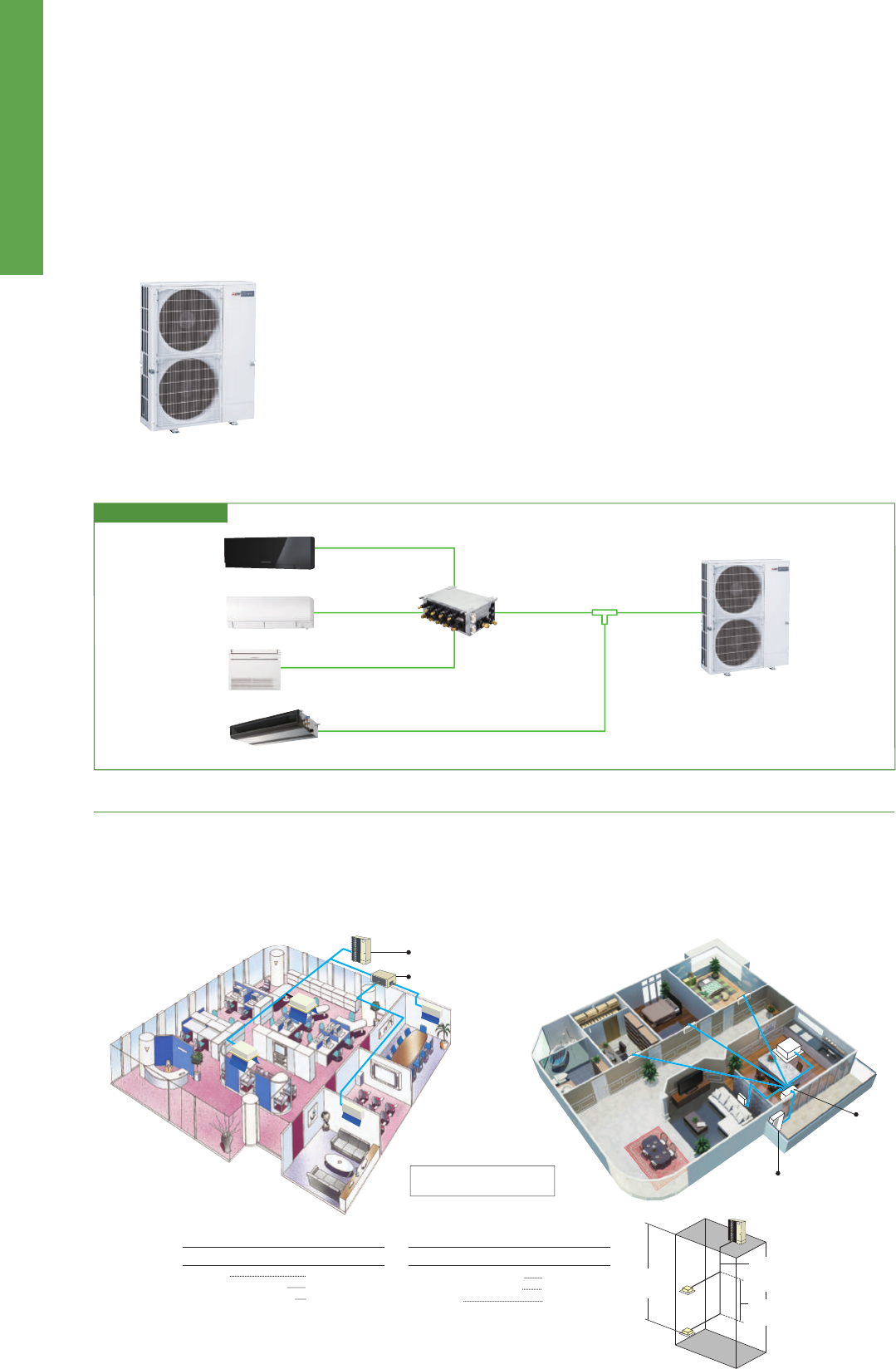
93
PUMYSERIES
Air conditioning system supports replacement work by simplifying the installa-
tion process. Ideal for supporting renewal needs at small offices and stores,
home offices, etc.
EXAMPLE SYSTEM
The two-pipe zoned system designed for Heat Pump Operation
PUMY series make use of a two-pipe refrigerant system, which allows for system changeover from cooling to heating, ensuring that a constant
indoor climate is maintained in all zones. The compact outdoor unit utilizes R410A refrigerant and an INVERTER-driven compressor to use energy
effectively.
With a wide range of indoor unit line-up in connection with a flexible piping system, PUMY series can be configured for all applications. Up to 12
indoor units can be connected with up to 130% connected capacity to maximize engineer's design options. This feature allows easy air condition-
ing in each area with convenient individual controllers.
PUMY-P112/125/140VKM2
PUMY-P112/125/140YKM2
2D-4D72
Cooling Capacity
(nominal)
Temp. Range of Cooling*
5
Temp. Range of Heating
Heating Capacity
(nominal)
Sound Pressure Level
(measured in anechoic room)
Indoor
27°C DB / 19°C WB
20°C DB
Cooling
Heating
Outdoor
35°C
7°C DB / 6°C WB
Piping Length
7.5m
7.5m
Level Difference
0m
0m
Indoor Unit Connectable
Refrigerant Piping Diameter
Fan
Compressor
External Dimensions (H × W × D)
Weight
Liquid Pipe
Gas Pipe
Type × Quantity
Air Flow Rate
Motor Output
Type × Quantity
Starting Method
Motor Output
mm
mm
m
3
/min
L/s
cfm
kW
kW
mm
kg
*
1
*
2
50 to 130% of outdoor unit capacity
9.52 Flare
15.88 Flare
Propeller Fan × 2
110
1,883
3,884
0.06 + 0.06
Scroll hermetic compressor × 1
Inverter
1,338×1,050×330 (+25)
2.9 3.5
122
3.9 2.9 3.5
125
3.9
kW
kW
A
kW/kW
W.B.
D.B.
kW
kW
A
kW/kW
D.B.
W.B.
City Multi
Branch Box
Mixed System
dB <A>
1-phase 220 - 240V 50Hz 3-phase 380 - 415V 50Hz
Model
Power Source
12.5
2.79
12.87 - 12.32 - 11.80
4.48
15.0 - 24.0°C
-5.0 - 46°C
14.0
3.04
14.03 - 13.42 - 12.86
4.61
15.0 - 27.0°C
-20.0 - 15.0°C
15 - 140/9
15 - 100/8
15 - 140*
3
/10
49 / 51
14.0
3.46
15.97 - 15.27 - 14.64
4.05
15.0 - 24.0°C
-5.0 - 46°C
16.0
3.74
17.26 - 16.51 - 15.82
4.28
15.0 - 27.0°C
-20.0 - 15.0°C
15 - 140/10
15 - 100/8
15 - 140*
3
/10*
4
50 / 52
15.5
4.52
20.86 - 19.95 - 19.12
3.43
15.0 - 24.0°C
-5.0 - 46°C
18.0
4.47
20.63 - 19.73 - 18.91
4.03
15.0 - 27.0°C
-20.0 - 15.0°C
15 - 140/12
15 - 100/8
15 - 140*
3
/10*
4
51 / 53
12.5
2.79
4.46 - 4.24 - 4.09
4.48
15.0 - 24.0°C
-5.0 - 46°C
14.0
3.04
4.86 - 4.62 - 4.45
4.61
15.0 - 27.0°C
-20.0 - 15.0°C
15 - 140/9
15 - 100/8
15 - 140*
3
/10
49 / 51
14.0
3.46
5.53 - 5.26 - 5.07
4.05
15.0 - 24.0°C
-5.0 - 46°C
16.0
3.74
5.98 - 5.68 - 5.48
4.28
15.0 - 27.0°C
-20.0 - 15.0°C
15 - 140/10
15 - 100/8
15 - 140*
3
/10*
4
50 / 52
15.5
4.52
7.23 - 6.87 - 6.62
3.43
15.0 - 24.0°C
-5.0 - 46°C
18.0
4.47
7.15 - 6.79 - 6.55
4.03
15.0 - 27.0°C
-20.0 - 15.0°C
15 - 140/12
15 - 100/8
15 - 140*
3
/10*
4
51 / 53
PUMY-P140VKM2 PUMY-P112YKM2 PUMY-P125YKM2 PUMY-P140YKM2PUMY-P125VKM2PUMY-P112VKM2
Branch Box
Total Input
Operating Current
Dimensions
Weight
Piping
[diameter]
Branch
[Indoor Side]
Main
[Outdoor Side]
Connection Method
to Indoor Unit
to Outdoor Unit
Wiring
Source
Outdoor (V/Phase/Hz)
Liquid
Gas
Liquid
Gas
kW
mm
kg
mm
mm
mm
mm
H × W × D
A
PAC-MK51BC
Max. 5
Outdoor power supply, Branch Box / Outdoor separate power supply
Single phase, 220/230/240V, 50Hz, Single phase, 220V, 60Hz
PAC-MK31BC
Max. 3
Type
Model Name
Connectable Number of Indoor Units
Power
Supply
INVERTER MULTI
PUMY SERIES
MSZ-FH
MFZ-KJ
CITY MULTI
indoor unit
Branch Box
MSZ-EF
4D83-6C 3D-5D
Total length
Maximum allowable length
Farthest indoor from first branch
300
150 (175 equivalent)
30
Outdoor unit
Indoor unit
Between indoor units
top-bottom differential
12m
Refrigerant Piping Lengths
Maximum meters
[P112–140V/YKM2]
Furthest piping length
175m
(equivalent length)
(actual length 150m)
Silent mode can reduce sound
pressure level by 3dB(A)
Indoor/outdoor (outdoor higher)
Indoor/outdoor (outdoor lower)
Indoor/indoor
50
40
12
Vertical differentials between units
Maximum meters
Top-bottom
differential
50m
Outdoor unit
Outdoor unit
Branch Box
Small Offices Residence
Power Input
Current Input
EER
Indoor Temp.
Outdoor Temp.
Power Input
Current Input
COP
Indoor Temp.
Outdoor Temp.
Total Capacity
Model / Quantity
*1,*2 Nominal conditions
*3 Up to P100 when connecting via branch box.
*4 Up to 11 units when connecting via 2 branch boxes
*5 10 to 46°C D.B.: When connecting PKFY-P15/20/25VBM, PFFY-P20/25/32VKM and PFFY-P20/25/32VLE(R)M type indoor unit.
0.003
0.05
170 - 450 - 280
9.52
15.88
3-wire + Earth wire
3-wire + Earth wire
Flared Brazed
7.4
6.35 × 5
9.52 × 4, 12.7 × 1
6.7
6.35 × 3
9.52 × 3
PAC-MK51BCB
Max. 5
PAC-MK31BCB
Max. 3
7.0
6.35 × 5
9.52 × 4, 12.7 × 1
6.5
6.35 × 3
9.52 × 3
Branch Box
PUMY-V(Y)KM2
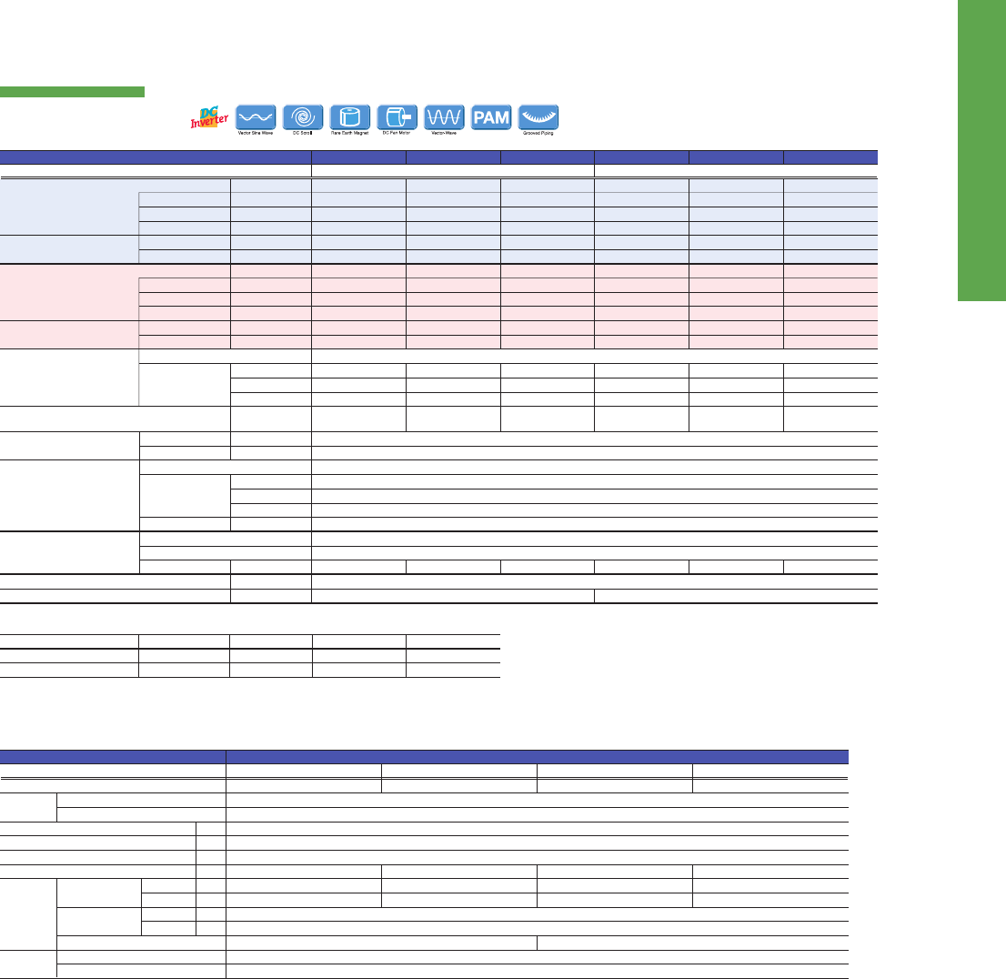
94
PUMYSERIES
Air conditioning system supports replacement work by simplifying the installa-
tion process. Ideal for supporting renewal needs at small offices and stores,
home offices, etc.
EXAMPLE SYSTEM
The two-pipe zoned system designed for Heat Pump Operation
PUMY series make use of a two-pipe refrigerant system, which allows for system changeover from cooling to heating, ensuring that a constant
indoor climate is maintained in all zones. The compact outdoor unit utilizes R410A refrigerant and an INVERTER-driven compressor to use energy
effectively.
With a wide range of indoor unit line-up in connection with a flexible piping system, PUMY series can be configured for all applications. Up to 12
indoor units can be connected with up to 130% connected capacity to maximize engineer's design options. This feature allows easy air condition-
ing in each area with convenient individual controllers.
PUMY-P112/125/140VKM2
PUMY-P112/125/140YKM2
2D-4D72
Cooling Capacity
(nominal)
Temp. Range of Cooling*
5
Temp. Range of Heating
Heating Capacity
(nominal)
Sound Pressure Level
(measured in anechoic room)
Indoor
27°C DB / 19°C WB
20°C DB
Cooling
Heating
Outdoor
35°C
7°C DB / 6°C WB
Piping Length
7.5m
7.5m
Level Difference
0m
0m
Indoor Unit Connectable
Refrigerant Piping Diameter
Fan
Compressor
External Dimensions (H × W × D)
Weight
Liquid Pipe
Gas Pipe
Type × Quantity
Air Flow Rate
Motor Output
Type × Quantity
Starting Method
Motor Output
mm
mm
m
3
/min
L/s
cfm
kW
kW
mm
kg
*
1
*
2
50 to 130% of outdoor unit capacity
9.52 Flare
15.88 Flare
Propeller Fan × 2
110
1,883
3,884
0.06 + 0.06
Scroll hermetic compressor × 1
Inverter
1,338×1,050×330 (+25)
2.9 3.5
122
3.9 2.9 3.5
125
3.9
kW
kW
A
kW/kW
W.B.
D.B.
kW
kW
A
kW/kW
D.B.
W.B.
City Multi
Branch Box
Mixed System
dB <A>
1-phase 220 - 240V 50Hz 3-phase 380 - 415V 50Hz
Model
Power Source
12.5
2.79
12.87 - 12.32 - 11.80
4.48
15.0 - 24.0°C
-5.0 - 46°C
14.0
3.04
14.03 - 13.42 - 12.86
4.61
15.0 - 27.0°C
-20.0 - 15.0°C
15 - 140/9
15 - 100/8
15 - 140*
3
/10
49 / 51
14.0
3.46
15.97 - 15.27 - 14.64
4.05
15.0 - 24.0°C
-5.0 - 46°C
16.0
3.74
17.26 - 16.51 - 15.82
4.28
15.0 - 27.0°C
-20.0 - 15.0°C
15 - 140/10
15 - 100/8
15 - 140*
3
/10*
4
50 / 52
15.5
4.52
20.86 - 19.95 - 19.12
3.43
15.0 - 24.0°C
-5.0 - 46°C
18.0
4.47
20.63 - 19.73 - 18.91
4.03
15.0 - 27.0°C
-20.0 - 15.0°C
15 - 140/12
15 - 100/8
15 - 140*
3
/10*
4
51 / 53
12.5
2.79
4.46 - 4.24 - 4.09
4.48
15.0 - 24.0°C
-5.0 - 46°C
14.0
3.04
4.86 - 4.62 - 4.45
4.61
15.0 - 27.0°C
-20.0 - 15.0°C
15 - 140/9
15 - 100/8
15 - 140*
3
/10
49 / 51
14.0
3.46
5.53 - 5.26 - 5.07
4.05
15.0 - 24.0°C
-5.0 - 46°C
16.0
3.74
5.98 - 5.68 - 5.48
4.28
15.0 - 27.0°C
-20.0 - 15.0°C
15 - 140/10
15 - 100/8
15 - 140*
3
/10*
4
50 / 52
15.5
4.52
7.23 - 6.87 - 6.62
3.43
15.0 - 24.0°C
-5.0 - 46°C
18.0
4.47
7.15 - 6.79 - 6.55
4.03
15.0 - 27.0°C
-20.0 - 15.0°C
15 - 140/12
15 - 100/8
15 - 140*
3
/10*
4
51 / 53
PUMY-P140VKM2 PUMY-P112YKM2 PUMY-P125YKM2 PUMY-P140YKM2PUMY-P125VKM2PUMY-P112VKM2
Branch Box
Total Input
Operating Current
Dimensions
Weight
Piping
[diameter]
Branch
[Indoor Side]
Main
[Outdoor Side]
Connection Method
to Indoor Unit
to Outdoor Unit
Wiring
Source
Outdoor (V/Phase/Hz)
Liquid
Gas
Liquid
Gas
kW
mm
kg
mm
mm
mm
mm
H × W × D
A
PAC-MK51BC
Max. 5
Outdoor power supply, Branch Box / Outdoor separate power supply
Single phase, 220/230/240V, 50Hz, Single phase, 220V, 60Hz
PAC-MK31BC
Max. 3
Type
Model Name
Connectable Number of Indoor Units
Power
Supply
INVERTER MULTI
PUMY SERIES
MSZ-FH
MFZ-KJ
CITY MULTI
indoor unit
Branch Box
MSZ-EF
4D83-6C 3D-5D
Total length
Maximum allowable length
Farthest indoor from first branch
300
150 (175 equivalent)
30
Outdoor unit
Indoor unit
Between indoor units
top-bottom differential
12m
Refrigerant Piping Lengths
Maximum meters
[P112–140V/YKM2]
Furthest piping length
175m
(equivalent length)
(actual length 150m)
Silent mode can reduce sound
pressure level by 3dB(A)
Indoor/outdoor (outdoor higher)
Indoor/outdoor (outdoor lower)
Indoor/indoor
50
40
12
Vertical differentials between units
Maximum meters
Top-bottom
differential
50m
Outdoor unit
Outdoor unit
Branch Box
Small Offices Residence
Power Input
Current Input
EER
Indoor Temp.
Outdoor Temp.
Power Input
Current Input
COP
Indoor Temp.
Outdoor Temp.
Total Capacity
Model / Quantity
*1,*2 Nominal conditions
*3 Up to P100 when connecting via branch box.
*4 Up to 11 units when connecting via 2 branch boxes
*5 10 to 46°C D.B.: When connecting PKFY-P15/20/25VBM, PFFY-P20/25/32VKM and PFFY-P20/25/32VLE(R)M type indoor unit.
0.003
0.05
170 - 450 - 280
9.52
15.88
3-wire + Earth wire
3-wire + Earth wire
Flared Brazed
7.4
6.35 × 5
9.52 × 4, 12.7 × 1
6.7
6.35 × 3
9.52 × 3
PAC-MK51BCB
Max. 5
PAC-MK31BCB
Max. 3
7.0
6.35 × 5
9.52 × 4, 12.7 × 1
6.5
6.35 × 3
9.52 × 3
Branch Box
PUMY-V(Y)KM2
95
Indoor Unit Compatibility Table
Indoor Unit
Outdoor Unit Inverter Models Heat pump type
MXZ-
2D33VA
*
4
*
4
*
4
*
4
*
4
*
4
*
4
*
4
*
4
*
4
MXZ-
2D42VA
MXZ-
2D53VA/H
*
4
*
4
MXZ-
2E53VAHZ
MXZ-
3D54VA2
MXZ-
2DM40VA
MXZ-
3DM50VA
MXZ-
3D68VA
MXZ-
4E83VA
*
4
MXZ-
4E83VAHZ
MXZ-
5E102VA
MXZ-
4D72VA
MXZ-
6D122VA
M series Wall-
Mounted
S series 4-way
Cassette
P series 4-way
Cassette
Ceiling-
Suspended
Ceiling-
Concealed
Ceiling-
Concealed
Floor-
Standing
1-way
Cassette
Wall-
Mounted
MSZ-FH25VE(2)
MSZ-FH35VE(2)
MSZ-FH50VE(2)
MSZ-SF15VA
MSZ-SF20VA
MSZ-SF25VE2(3)
MSZ-SF35VE2(3)
MSZ-SF42VE2(3)
MSZ-SF50VE2(3)
MSZ-GF60VE(2)
MSZ-GF71VE(2)
MSZ-EF18VE2(3)W/B/S
MSZ-EF22VE2(3)W/B/S
MSZ-EF25VE2(3)W/B/S
MSZ-EF35VE2(3)W/B/S
MSZ-EF42VE2(3)W/B/S
MSZ-EF50VE2(3)W/B/S
MFZ-KJ25VE(2)
MFZ-KJ35VE(2)
MFZ-KJ50VE(2)
MLZ-KA25VA
MLZ-KA35VA
MLZ-KA50VA
MSZ-DM25VA
MSZ-DM35VA
SLZ-KF25VA
SLZ-KF35VA
SLZ-KF50VA
SLZ-KF60VA
SEZ-KD25VAQ
SEZ-KD25VAL
SEZ-KD35VAQ
SEZ-KD35VAL
SEZ-KD50VAQ
SEZ-KD50VAL
SEZ-KD60VAQ
SEZ-KD60VAL
SEZ-KD71VAQ
SEZ-KD71VAL
PLA-RP50BA
PLA-RP60BA
PLA-RP71BA
PCA-RP50KAQ
PCA-RP60KAQ
PCA-RP71KAQ
PEAD-RP50JAQ
PEAD-RP50JALQ
PEAD-RP60JAQ
PEAD-RP60JALQ
PEAD-RP71JAQ
PEAD-RP71JALQ
Possible combinations of outdoor units and indoor units are shown below.
*1 Maximum total current of indoor units: 3A or less.
*2 The combination is still under evaluation.
*3 SEZ-KD25 cannot be connected with MXZ-2D(E)/3D/4E/5E when total capacity of connected indoor units is equivalent to outdoor capacity (capacity ratio is 1).
*4 MXZ outdoor units are not designed to operate with a single indoor unit with one-to-one piping work. Please install at least two indoor units.
*5 When connecting the MFZ-KJ Series indoor unit, additional refrigerant is required. For details, please refer to page 88.
*6 Regarding MXZ-2D33, the second unit should be a different type in the case of selecting one MFZ-KJ.
*7 P series cannot be connected with MXZ-4E83VAHZ when ampere limit adjustment function is operated.
*8 If connecting four indoor units to the MXZ-4D72VA, up to two units can be connected to each MFZ-KJ.
*1*1*1
*2
*1
*2
*1*1
*3
*3
*1*1*1*1*1*1
*1*1*1
*1*1*1
*1*1*1
*1*1
*7
*7
*7
*7
*7
*7
*1
*
5
*
6
*
5
*
5
*
5
*
5
*
5
*
5
*
5
*
5
*
5
*
5
*
8
*
8
*
8
Temperature conditions are based on JIS B8616.
Conditions for specications
Heating
How to read a model name
Refrigerant piping length ; 5m
1) M & S Series
3) MXZ Series
Cooling
Outdoor
Indoor
Outdoor
Indoor
35˚C DB, 24˚C WB
20˚C DB
7˚C DB, 6˚C WB
27˚C DB, 19˚C WB
The gures for total input are based on the following voltages.
Sound pressure level
• The actual sound level depends on the distance from the unit and the acoustic environment.
• The sound pressure measurement is conducted in an anechoic chamber.
M Series
S Series
P Series (except for PEA)
MXZ Series
POWERFUL HEATING Series
PEA Series
M
Z
F
H
25
V
M
X
Z
4
D/E/DM
72
V
A
HZ
M : M
Series S : S Series
"S"= Wall-mounted , "F"= Compact oor-standing , "E"= Compact ceiling-concealed ,
"L"= 4- or 1-way cassette , "U"= Outdoor unit
"Z"= Inverter heat pump , "H"= Fixed-speed heat pump , "blank"= Cooling only
Series
Generation
Rated cooling capacity (kW base)
230V / Single phase / 50Hz
"A"= R410A with new A control , "B"= R410A with conventional control ,
"E"= R410A with new A control & ErP correspondance
"HZ"= Hyper Heating model , "H"= Anti-freeze heater equipped model ,
"S"= Silver indoor unit , "W"= White indoor unit , "B"= Black indoor unit
M Series
Multi-system outdoor unit (heat pump)
Inverter heat pump
Maximum number of connectable indoor units
Generation / Type
Rated cooling capacity (kW base)
"V"= 230V / Single phase / 50Hz
"A"= R410A with new A control
"HZ"= Hyper Heating model , "H"= Anti-freeze heater equipped model
400V/Three phase/50Hz
-
400V/Three phase/50Hz
VE,VA,VHA,VKA:230V/Single phase/50Hz
YA,YHA,YKA:400V/Three phase/50Hz
Indoor unit Outdoor unitSeries
2) P Series
P
H
Z
ZRP/RP/P
SHW
71
V
H
A
P
Series
"K"= Wall-mounted , "S"= Floor-standing , "L"= 4-way cassette , "E"= Ceiling-concealed ,
"C"= Ceiling-suspended , "U"= Outdoor unit
"H"= For heating and cooling , "blank"= Cooling only
"Z"= Inverter , "blank"= Fixed-speed
"ZRP"/ "RP"= R410A & cleaning-free pipe reuse , "P"=R410A
"SH"= Powerful heating ZUBADAN , "W"= can be used as air to water application
Rated cooling capacity (kW base)
"V"= 230V / Single phase / 50Hz , "Y"= 400V / Three phase / 50Hz
Generation
"A"= A control
U
S
E
HZ
*1*7
*1*7
*1*7
*1*7
*1*7
*1*7
MSZ-HJ25VA
MSZ-HJ35VA
MSZ-HJ50VA
MSZ-HJ60VA
MSZ-HJ71VA

96
Indoor Unit Compatibility Table
Indoor Unit
Outdoor Unit Inverter Models Heat pump type
MXZ-
2D33VA
*
4
*
4
*
4
*
4
*
4
*
4
*
4
*
4
*
4
*
4
MXZ-
2D42VA
MXZ-
2D53VA/H
*
4
*
4
MXZ-
2E53VAHZ
MXZ-
3D54VA2
MXZ-
2DM40VA
MXZ-
3DM50VA
MXZ-
3D68VA
MXZ-
4E83VA
*
4
MXZ-
4E83VAHZ
MXZ-
5E102VA
MXZ-
4D72VA
MXZ-
6D122VA
M series Wall-
Mounted
S series 4-way
Cassette
P series 4-way
Cassette
Ceiling-
Suspended
Ceiling-
Concealed
Ceiling-
Concealed
Floor-
Standing
1-way
Cassette
Wall-
Mounted
MSZ-FH25VE(2)
MSZ-FH35VE(2)
MSZ-FH50VE(2)
MSZ-SF15VA
MSZ-SF20VA
MSZ-SF25VE2(3)
MSZ-SF35VE2(3)
MSZ-SF42VE2(3)
MSZ-SF50VE2(3)
MSZ-GF60VE(2)
MSZ-GF71VE(2)
MSZ-EF18VE2(3)W/B/S
MSZ-EF22VE2(3)W/B/S
MSZ-EF25VE2(3)W/B/S
MSZ-EF35VE2(3)W/B/S
MSZ-EF42VE2(3)W/B/S
MSZ-EF50VE2(3)W/B/S
MFZ-KJ25VE(2)
MFZ-KJ35VE(2)
MFZ-KJ50VE(2)
MLZ-KA25VA
MLZ-KA35VA
MLZ-KA50VA
MSZ-DM25VA
MSZ-DM35VA
SLZ-KF25VA
SLZ-KF35VA
SLZ-KF50VA
SLZ-KF60VA
SEZ-KD25VAQ
SEZ-KD25VAL
SEZ-KD35VAQ
SEZ-KD35VAL
SEZ-KD50VAQ
SEZ-KD50VAL
SEZ-KD60VAQ
SEZ-KD60VAL
SEZ-KD71VAQ
SEZ-KD71VAL
PLA-RP50BA
PLA-RP60BA
PLA-RP71BA
PCA-RP50KAQ
PCA-RP60KAQ
PCA-RP71KAQ
PEAD-RP50JAQ
PEAD-RP50JALQ
PEAD-RP60JAQ
PEAD-RP60JALQ
PEAD-RP71JAQ
PEAD-RP71JALQ
Possible combinations of outdoor units and indoor units are shown below.
*1 Maximum total current of indoor units: 3A or less.
*2 The combination is still under evaluation.
*3 SEZ-KD25 cannot be connected with MXZ-2D(E)/3D/4E/5E when total capacity of connected indoor units is equivalent to outdoor capacity (capacity ratio is 1).
*4 MXZ outdoor units are not designed to operate with a single indoor unit with one-to-one piping work. Please install at least two indoor units.
*5 When connecting the MFZ-KJ Series indoor unit, additional refrigerant is required. For details, please refer to page 88.
*6 Regarding MXZ-2D33, the second unit should be a different type in the case of selecting one MFZ-KJ.
*7 P series cannot be connected with MXZ-4E83VAHZ when ampere limit adjustment function is operated.
*8 If connecting four indoor units to the MXZ-4D72VA, up to two units can be connected to each MFZ-KJ.
*1*1*1
*2
*1
*2
*1*1
*3
*3
*1*1*1*1*1*1
*1*1*1
*1*1*1
*1*1*1
*1*1
*7
*7
*7
*7
*7
*7
*1
*
5
*
6
*
5
*
5
*
5
*
5
*
5
*
5
*
5
*
5
*
5
*
5
*
8
*
8
*
8
Temperature conditions are based on JIS B8616.
Conditions for specications
Heating
How to read a model name
Refrigerant piping length ; 5m
1) M & S Series
3) MXZ Series
Cooling
Outdoor
Indoor
Outdoor
Indoor
35˚C DB, 24˚C WB
20˚C DB
7˚C DB, 6˚C WB
27˚C DB, 19˚C WB
The gures for total input are based on the following voltages.
Sound pressure level
• The actual sound level depends on the distance from the unit and the acoustic environment.
• The sound pressure measurement is conducted in an anechoic chamber.
M Series
S Series
P Series (except for PEA)
MXZ Series
POWERFUL HEATING Series
PEA Series
M
Z
F
H
25
V
M
X
Z
4
D/E/DM
72
V
A
HZ
M : M
Series S : S Series
"S"= Wall-mounted , "F"= Compact oor-standing , "E"= Compact ceiling-concealed ,
"L"= 4- or 1-way cassette , "U"= Outdoor unit
"Z"= Inverter heat pump , "H"= Fixed-speed heat pump , "blank"= Cooling only
Series
Generation
Rated cooling capacity (kW base)
230V / Single phase / 50Hz
"A"= R410A with new A control , "B"= R410A with conventional control ,
"E"= R410A with new A control & ErP correspondance
"HZ"= Hyper Heating model , "H"= Anti-freeze heater equipped model ,
"S"= Silver indoor unit , "W"= White indoor unit , "B"= Black indoor unit
M Series
Multi-system outdoor unit (heat pump)
Inverter heat pump
Maximum number of connectable indoor units
Generation / Type
Rated cooling capacity (kW base)
"V"= 230V / Single phase / 50Hz
"A"= R410A with new A control
"HZ"= Hyper Heating model , "H"= Anti-freeze heater equipped model
400V/Three phase/50Hz
-
400V/Three phase/50Hz
VE,VA,VHA,VKA:230V/Single phase/50Hz
YA,YHA,YKA:400V/Three phase/50Hz
Indoor unit Outdoor unitSeries
2) P Series
P
H
Z
ZRP/RP/P
SHW
71
V
H
A
P
Series
"K"= Wall-mounted , "S"= Floor-standing , "L"= 4-way cassette , "E"= Ceiling-concealed ,
"C"= Ceiling-suspended , "U"= Outdoor unit
"H"= For heating and cooling , "blank"= Cooling only
"Z"= Inverter , "blank"= Fixed-speed
"ZRP"/ "RP"= R410A & cleaning-free pipe reuse , "P"=R410A
"SH"= Powerful heating ZUBADAN , "W"= can be used as air to water application
Rated cooling capacity (kW base)
"V"= 230V / Single phase / 50Hz , "Y"= 400V / Three phase / 50Hz
Generation
"A"= A control
U
S
E
HZ
*1*7
*1*7
*1*7
*1*7
*1*7
*1*7
MSZ-HJ25VA
MSZ-HJ35VA
MSZ-HJ50VA
MSZ-HJ60VA
MSZ-HJ71VA

POWERFUL
HEATING
SERIES
ZUBADAN SERIES
SELECTION
Line-up consists of two series.
Choose the series that best matches the building layout.
The line-up includes outdoor unit models 112-140 class and three types of indoor units.
Outdoor Unit Indoor Unit
MSZ-FH/MFZ-KJ VEHZ SERIES
The line-up includes outdoor models 25–50
Outdoor Unit Indoor Unit
MUZ-FH25/35VEHZ
MUFZ-KJ25/35VEHZ
MUZ-FH50VEHZ
MUFZ-KJ50VEHZ
Wall-mounted
PKA Series
PEAD Series
Ceiling-concealed
Wall-mounted
PLA Series
4-way cassette
PUHZ-SHW112VHA
PUHZ-SHW112/140YHA
MFZ-KJ25/35/50VE
MSZ-FH25/35/50VE
Floor-standing
MXZ-VAHZ SERIES
Outdoor Unit
MXZ-2E53VAHZ
MXZ-4E83VAHZ
97
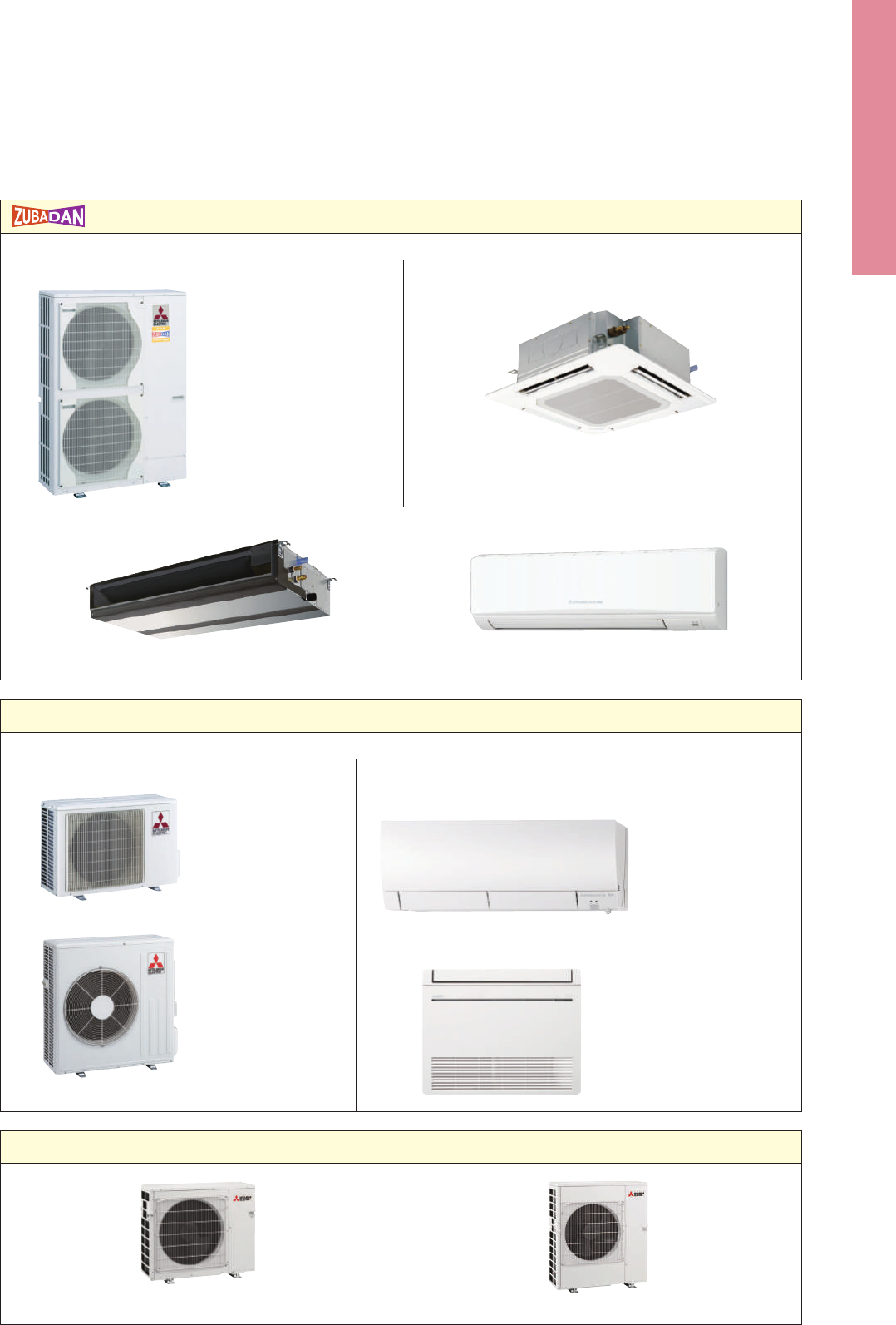
POWERFUL
HEATING
SERIES
ZUBADAN SERIES
SELECTION
Line-up consists of two series.
Choose the series that best matches the building layout.
The line-up includes outdoor unit models 112-140 class and three types of indoor units.
Outdoor Unit Indoor Unit
MSZ-FH/MFZ-KJ VEHZ SERIES
The line-up includes outdoor models 25–50
Outdoor Unit Indoor Unit
MUZ-FH25/35VEHZ
MUFZ-KJ25/35VEHZ
MUZ-FH50VEHZ
MUFZ-KJ50VEHZ
Wall-mounted
PKA Series
PEAD Series
Ceiling-concealed
Wall-mounted
PLA Series
4-way cassette
PUHZ-SHW112VHA
PUHZ-SHW112/140YHA
MFZ-KJ25/35/50VE
MSZ-FH25/35/50VE
Floor-standing
MXZ-VAHZ SERIES
Outdoor Unit
MXZ-2E53VAHZ
MXZ-4E83VAHZ
98
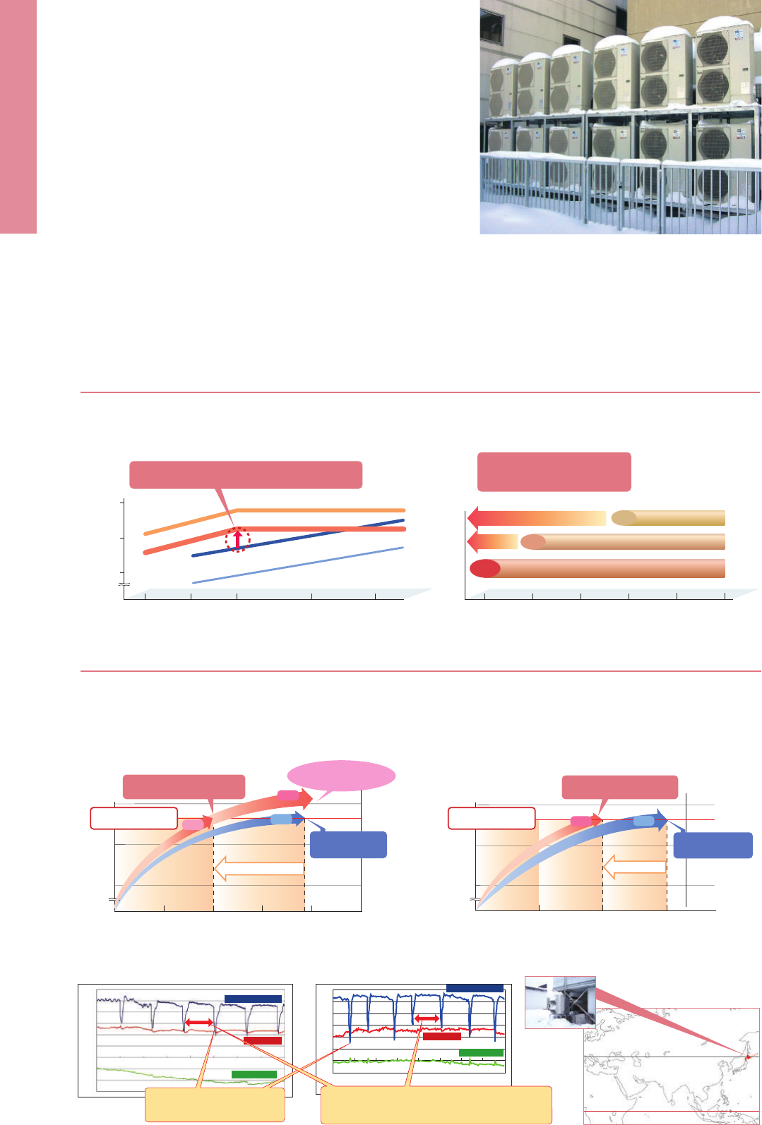
ZUBADAN
SERIES
The ZUBADAN Series incorporates an original Flash Injection technology that
improves the already high heating capacity of the system. This new member of
the series line-up ensures comfortable heat pump-driven heating performance in
cold regions.
Guaranteed heating operation
range is extended to -25°C
ambient temperature
-10
o
C
-5
o
C0
o
C
-15
o
C-20
o
C-25
o
C
-25
o
C
-20
o
C
-11
o
C
ZUBADAN 4-5HP
Power INV 4&5HP
Power INV 3HP
Heating
capacity (kW)
Outdoor-air temperature
15
10
-7
o
C-15
o
C-20
o
C-25
o
C0
o
C
P
ower INV 4HP
Approx. 30% higher than model one size larger
(example of 4HP model)
ZUBADAN 5HP
ZUBADAN 4HP
Power INV 5HP
5
Enhanced Comfort
The Flash Injection circuit improves start-up and recover from the defrosting operation. A newly introduced defrost operation control also improves
defrost frequency. These features enable the temperature to reach the set temperature more quickly, and contribute to maintaining it at the
desired setting.
Improved Heating Performance
Mitsubishi Electric’s unique “Flash Injection” circuit achieves remarkably high heating performance. This technology has resulted in an excellent
heating capacity rating in outdoor temperatures as low as -15°C, and the guaranteed heating operation range of the heating mode has been
extended to -25°C. Accordingly, the heat-pump units of the ZUBADAN Series are perfect for warming homes in the coldest of regions.
Heating
capacity (kW)
Operation time (min)
10
15
5
0
0510 15 20
Normal INV:
45
o
C in 19min
Discharged air
temperature reaches
50
o
C
(in stable condition)
19min
Approx. 50% faster
10min
Stable
13kW with 45°C indoor
air outlet temperature
ZUBADAN Defrost Control and Faster Recovery from Defrost Operation Field Test Results: Office building in Asahikawa, Hokkaido, Japan
Quick Start-up
■ Operation data for 25 Jan. 2005
■ Operation at +2°C outdoor temperature ■ Operation at -20°C outdoor temperature
■ Operation data for 2 Dec. 2004
8:00 10:0012:00 14:0016:00 18:0020:00 22:00
60°C
50°C
40°C
30°C
20°C
10°C
0°C
-10°C
20:0018:00
60
°C
50
°C
40
°C
30
°C
20
°C
10
°C
0
°C
-10
°C
-20
°C
-30
°C
22:000:002:004:006:00
Indoor outlet temp.
Room temp.
Outdoor temp.
Indoor outlet temp.
Room temp.
Outdoor temp.
Reduced defrosting operation time
from 4 to 3 minutes.
ZUBADAN Defrost Control maintained a maximum interval
of 150 minutes between defrosting operations at outdoor
temperatures of approximately -20°C and 0°C.
Heating
capacity (kW)
Operation time (min)
10
15
5
0
02010 30
Normal INV:
45
o
C in 30min
33% faster
20min
30min
ZUBADAN rises quickly,
45°C in 10min
ZUBADAN rises quickly,
45°C in 20min
LEVB
LEVC
LEVA
Mitsubishi Electric’s Flash Injection Technology
The Key to High Heating Performance at Low Outdoor Temperatures
Heat Interchanger
(
HIC
)
Heat Interchanger
(
HIC
)
Heat
interchanger
(
HIC
)
A
HIC cross-sectional view
The compressor is subjected to a heavy load when com-
pressing liquid refrigerant, and the result is lower operation
efficiency. The addition of HIC supports refrigerant heat ex-
change at two different pressure levels. The heat-exchange
process transforms the injected liquid refrigerant into a gas
liquid state, thereby decreasing the load on the compressor
during the compression process.
The ZUBADAN Series is equipped with Mitsubishi Electric’s original Flash Injection
Circuit, which is comprised of a bypass circuit and heat interchanger (HIC). The
HIC transforms rerouted liquid refrigerant into a gas-liquid state to lower compres-
sion load. This process ensures excellent heating performance even when the out-
door temperature drops very low.
In traditional units, when the outdoor temperature is low, the volume of refrigerant
circulating in the compressor decreases due to the drop in refrigerant pressure
and the protection from overheating caused by high compression, thereby reduc-
ing heating capacity. The Flash Injection Circuit injects refrigerant to maintain the
refrigerant circulation volume and compressor operation load, thereby maintaining
heating capacity.
Purpose: Transform liquid refrigerant into
liquid-gas state
Effect: Injection circuit increases energy
efficiency
Refrigerant passes from the HIC into the compressor through
the injection port. Having two refrigerant inlets makes it pos-
sible to raise the volume of refrigerant being circulated when
the outdoor temperature is low and at the start of heating
operation.
Purpose: To increase the volume of refrigerant being circulated
Effect:
Improves heating capacity at low outdoor tempera-
tures, and enables higher indoor-air outlet temperature
adjustment and higher defrost operation speed
Refrigerant which has passed through LEV C
(refrigerant pressure lowered)
Refrigerant which hasn’t passed through LEV C
Discharge port
Refrigerant
flow
Suction port
Injection
port
Mollier Chart Image Representing Flash Injection
Circuit Operation
ZUBADAN
Injection Compressor
Injection Compressor
■ Flash Injection Circuit
B
A
A
B
B
Indoor
HEX
Power
receiver
Outdoor
HEX
Injection compressor
(
injection port
)
Flash Injection Circuit
LEV B
LEV C
LEV A
Flash Injection Circuit
13kW with 45°C indoor
air outlet temperature
✽
Units in photo are Japanese models.
European model specifications are different.
Installation
example
✽
For products with capacity over 12.0kW, SEER/SCOP values are measured based on EN14825. These values are for reference purposes only.
ErP Lot 10 Compliant with High Energy-efficiency Achieving SEER/SCOP
Rank A and A
+
Powerful heating yet annaully high energy efficiency in both cooling and heating, achieving rank A and A
+
.
Cooling
Heating
PLA-ZRP100BA
PUHZ-SHW112VHA
PLA-ZRP100BA
PUHZ-SHW112YHA
PLA-ZRP125BA
PUHZ-SHW140YHA
4.0
4.0
5.1
3.5
SEER
A
SCOP
A
+
SEER
A
SCOP
A
+
Minimum SCOP 3.8
Minimum SEER 4.6
5.5
5.5
99
ZUBADAN
SERIES
The ZUBADAN Series incorporates an original Flash Injection technology that
improves the already high heating capacity of the system. This new member of
the series line-up ensures comfortable heat pump-driven heating performance in
cold regions.
Guaranteed heating operation
range is extended to -25°C
ambient temperature
-10
o
C
-5
o
C0
o
C
-15
o
C-20
o
C-25
o
C
-25
o
C
-20
o
C
-11
o
C
ZUBADAN 4-5HP
Power INV 4&5HP
Power INV 3HP
Heating
capacity (kW)
Outdoor-air temperature
15
10
-7
o
C-15
o
C-20
o
C-25
o
C0
o
C
P
ower INV 4HP
Approx. 30% higher than model one size larger
(example of 4HP model)
ZUBADAN 5HP
ZUBADAN 4HP
Power INV 5HP
5
Enhanced Comfort
The Flash Injection circuit improves start-up and recover from the defrosting operation. A newly introduced defrost operation control also improves
defrost frequency. These features enable the temperature to reach the set temperature more quickly, and contribute to maintaining it at the
desired setting.
Improved Heating Performance
Mitsubishi Electric’s unique “Flash Injection” circuit achieves remarkably high heating performance. This technology has resulted in an excellent
heating capacity rating in outdoor temperatures as low as -15°C, and the guaranteed heating operation range of the heating mode has been
extended to -25°C. Accordingly, the heat-pump units of the ZUBADAN Series are perfect for warming homes in the coldest of regions.
Heating
capacity (kW)
Operation time (min)
10
15
5
0
0510 15 20
Normal INV:
45
o
C in 19min
Discharged air
temperature reaches
50
o
C
(in stable condition)
19min
Approx. 50% faster
10min
Stable
13kW with 45°C indoor
air outlet temperature
ZUBADAN Defrost Control and Faster Recovery from Defrost Operation Field Test Results: Office building in Asahikawa, Hokkaido, Japan
Quick Start-up
■ Operation data for 25 Jan. 2005
■ Operation at +2°C outdoor temperature ■ Operation at -20°C outdoor temperature
■ Operation data for 2 Dec. 2004
8:00 10:0012:00 14:0016:00 18:0020:00 22:00
60°C
50°C
40°C
30°C
20°C
10°C
0°C
-10°C
20:0018:00
60
°C
50
°C
40
°C
30
°C
20
°C
10
°C
0
°C
-10
°C
-20
°C
-30
°C
22:000:002:004:006:00
Indoor outlet temp.
Room temp.
Outdoor temp.
Indoor outlet temp.
Room temp.
Outdoor temp.
Reduced defrosting operation time
from 4 to 3 minutes.
ZUBADAN Defrost Control maintained a maximum interval
of 150 minutes between defrosting operations at outdoor
temperatures of approximately -20°C and 0°C.
Heating
capacity (kW)
Operation time (min)
10
15
5
0
02010 30
Normal INV:
45
o
C in 30min
33% faster
20min
30min
ZUBADAN rises quickly,
45°C in 10min
ZUBADAN rises quickly,
45°C in 20min
LEVB
LEVC
LEVA
Mitsubishi Electric’s Flash Injection Technology
The Key to High Heating Performance at Low Outdoor Temperatures
Heat Interchanger
(
HIC
)
Heat Interchanger
(
HIC
)
Heat
interchanger
(
HIC
)
A
HIC cross-sectional view
The compressor is subjected to a heavy load when com-
pressing liquid refrigerant, and the result is lower operation
efficiency. The addition of HIC supports refrigerant heat ex-
change at two different pressure levels. The heat-exchange
process transforms the injected liquid refrigerant into a gas
liquid state, thereby decreasing the load on the compressor
during the compression process.
The ZUBADAN Series is equipped with Mitsubishi Electric’s original Flash Injection
Circuit, which is comprised of a bypass circuit and heat interchanger (HIC). The
HIC transforms rerouted liquid refrigerant into a gas-liquid state to lower compres-
sion load. This process ensures excellent heating performance even when the out-
door temperature drops very low.
In traditional units, when the outdoor temperature is low, the volume of refrigerant
circulating in the compressor decreases due to the drop in refrigerant pressure
and the protection from overheating caused by high compression, thereby reduc-
ing heating capacity. The Flash Injection Circuit injects refrigerant to maintain the
refrigerant circulation volume and compressor operation load, thereby maintaining
heating capacity.
Purpose: Transform liquid refrigerant into
liquid-gas state
Effect: Injection circuit increases energy
efficiency
Refrigerant passes from the HIC into the compressor through
the injection port. Having two refrigerant inlets makes it pos-
sible to raise the volume of refrigerant being circulated when
the outdoor temperature is low and at the start of heating
operation.
Purpose: To increase the volume of refrigerant being circulated
Effect:
Improves heating capacity at low outdoor tempera-
tures, and enables higher indoor-air outlet temperature
adjustment and higher defrost operation speed
Refrigerant which has passed through LEV C
(refrigerant pressure lowered)
Refrigerant which hasn’t passed through LEV C
Discharge port
Refrigerant
flow
Suction port
Injection
port
Mollier Chart Image Representing Flash Injection
Circuit Operation
ZUBADAN
Injection Compressor
Injection Compressor
■ Flash Injection Circuit
B
A
A
B
B
Indoor
HEX
Power
receiver
Outdoor
HEX
Injection compressor
(
injection port
)
Flash Injection Circuit
LEV B
LEV C
LEV A
Flash Injection Circuit
13kW with 45°C indoor
air outlet temperature
✽
Units in photo are Japanese models.
European model specifications are different.
Installation
example
✽
For products with capacity over 12.0kW, SEER/SCOP values are measured based on EN14825. These values are for reference purposes only.
ErP Lot 10 Compliant with High Energy-efficiency Achieving SEER/SCOP
Rank A and A
+
Powerful heating yet annaully high energy efficiency in both cooling and heating, achieving rank A and A
+
.
Cooling
Heating
PLA-ZRP100BA
PUHZ-SHW112VHA
PLA-ZRP100BA
PUHZ-SHW112YHA
PLA-ZRP125BA
PUHZ-SHW140YHA
4.0
4.0
5.1
3.5
SEER
A
SCOP
A
+
SEER
A
SCOP
A
+
Minimum SCOP 3.8
Minimum SEER 4.6
5.5
5.5
100
FH VEHZ
SERIES
Unlike conventional air conditioning systems, the FH Series doesn’t lose heating
capacity when it’s cold outside. Original technologies ensure excellent heating
performance under extremely low outdoor temperatures and an impressive
guaranteed operating range.
High Energy Efficiency – Energy Rank
of A
+
or higher for All Models
With indoor units that combine functionality, design and capacity
and outdoor units equipped with a high-efficiency compressor, the
MUZ-FH VEHZ simultaneously achieves high heating capacity and
energy-saving performance.
Freeze-prevention Heater Equipped
as Standard
The Freeze-prevention heater restricts lowered capacity and opera-
tion shutdowns caused by the drain water freezing. This supports
stable operation in low-temperature environments.
Unparalleled Heating Performance
FH Series outdoor units are equipped with a high-output compressor that provides enhanced heating performance under low outdoor tempera-
tures. The heating operation range is extended down to -25°C.
Powerful
Core
for powerful
heating
Operation Range
-10
o
C-5
o
C0
o
C-15
o
C-20
o
C-25
o
C
-25
o
C
-20
o
C
-15
o
C
MSZ-FH VEHZ
MSZ-EF VEH
MSZ-SF
A special manufacturing technology,
“Heat Caulking Fixing Method,” has
been introduced to reduce compressor
size while maintaining a high compres-
sor output. This technology enables
the installation of a powerful compres-
sor in compact MUZ outdoor units. As
a result, excellent heating performance
is achieved when operating in cold out-
door environments.
Compact, Powerful Compressor
Compressor fixed using conventional
method (Arc spot-welded method)
Compressor fixed using Heat Caulking
Fixing Method
TNB175F
MUZ-
FH25VE
MUZ-
FH25VEHZ
MUZ-
FH35VE
MUZ-
FH35VEHZ
MUZ-
FH50VE
MUZ-
FH50VEHZ
SNB172F
Outer layer must be thick enough to hold the
cylinder.
Compressor size reduced while maintaining
same cylinder inner diameter.
Downsized
by 13%
Declared Capacity (at reference design temperature)
Frozen
drain
Without Freeze-prevention heater With Freeze-prevention heater
3.0kW
3.2kW
3.6kW
4.0kW
4.5kW
6.0kW
Drain does
not freeze
Bacteria
Viruses
Allergens
<Test No.> vrc.center, SMC No.23-002
Air, like water, is something we use everyday unconsciously. Ye t, clean, fresh air is a vital part of creating a healthy space for humans. Achieving
this healthy air is Plasma Quad, a plasma-based filter system that effectively removes four kinds of air pollutants; namely, bacteria, viruses,
allergens and dust, which the air contains countless particles of.
Principle of Plasma Quad
Plasma Quad attacks bacteria and viruses from inside the unit using a strong curtain-like
electrical field and discharge of electric current across the whole inlet-air opening of the
unit. Tungsten discharge electrodes are used as they provide both discharge capacity and
strength. In addition, through flattening the standard, round form of the field to a ribbon-like
shape, a strong electrical field is produced.
Test results have confirmed that Plasma Quad
neutralizes 99% of bacteria in 115 minutes in a
25m
3
test space.
[ Effective Range ]
Macro NanoParticulate size
Plasma Quad Air-purifying filter
Virus
Pollen Bacteria
Fish odours
Pet odours
Mold spores
Rubbish odours
DustVirusAllergens Bad Odours
In a test, air containing cat fur and pollen was
passed through the air cleaning device at the
low airflow setting. Before and after measure-
ments confirm that Plasma Quad neutralizes
94% of cat fur and 98% of pollen.
Plasma Quad off Plasma Quad on
Without Plasma Quad With Plasma Quad
Test results have confirmed that Plasma Quad
neutralizes 99% of virus particles in 65
minutes in a 25m
3
test space.
* Hepatic cells turn transparent when affected by a virus.
Round:
Flattened: a strong electrical field is produced.
Air
Virus
Bacteria
Dust
Air
Neutralization/inactivation
Plasma
space
<Test No.> KRCES-Bio.Te st Report No.23_0317
<Test No.> ITEA No.12M-RPTFEBO22
Dust
In a test, air containing dust and ticks was
passed through the air cleaning device at the
low airflow setting. Before and after measure-
ments confirm that Plasma Quad removes
88.6% of dust and ticks.
<Test No.> ITEA No.12M-RPTFEBO22
Effective deodorizing using
the air-purifying filter
(Image)
The FH Series is equipped with 3D i-see Sensor, an infrared-ray
sensor that measures the temperature at distant positions. While
moving to the left and right, eight vertically arranged sensor
elements analyze the room temperature in three dimensions. This
detailed analysis makes it possible to judge where people are
in the room, thus allowing creation of features such as “Indirect
airflow,” to avoid airflow hitting people directly, and “direct airflow”
to deliver airflow to where people are.
8 × 94 areas
(Image)
Divided into 94
Sensor with
eight elements
Sensor measures while
moving to the left to right
The indirect airflow setting can be used
when the flow of air feels too strong or
direct. For example, it can be used during
cooling to avert airflow and prevent body
temperature from becoming excessively
cooled.
Indirect Airflow
The sensors detect whether there are people in the room. When no-one is in the room,
the unit automatically switches to energy-saving mode.
The “3D i-see Sensor” detects people’s absence and the power consumption is automatically
reduced approximately 10% after 10 minutes and 20% after 60 minutes.
Absence Detection
This setting can be used to directly target
airflow at people such as for immediate
comfort when coming indoors on a hot
(cold) day.
Direct Airflow
Cooling Heating
SEER
9.1
SCOP
4.9
SCOP
4.8
SEER
7.2
SCOP
4.2
MUZ-FH25VEHZ MUZ-FH35VEHZ MUZ-FH50VEHZ
SEER
8.9
SEER Rank A
(
5.1
)
SCOP Rank A
(
3.8
)
Operation Guaranteed at
Outside Temperature of –25°C
101
FH VEHZ
SERIES
Unlike conventional air conditioning systems, the FH Series doesn’t lose heating
capacity when it’s cold outside. Original technologies ensure excellent heating
performance under extremely low outdoor temperatures and an impressive
guaranteed operating range.
High Energy Efficiency – Energy Rank
of A
+
or higher for All Models
With indoor units that combine functionality, design and capacity
and outdoor units equipped with a high-efficiency compressor, the
MUZ-FH VEHZ simultaneously achieves high heating capacity and
energy-saving performance.
Freeze-prevention Heater Equipped
as Standard
The Freeze-prevention heater restricts lowered capacity and opera-
tion shutdowns caused by the drain water freezing. This supports
stable operation in low-temperature environments.
Unparalleled Heating Performance
FH Series outdoor units are equipped with a high-output compressor that provides enhanced heating performance under low outdoor tempera-
tures. The heating operation range is extended down to -25°C.
Powerful
Core
for powerful
heating
Operation Range
-10
o
C-5
o
C0
o
C-15
o
C-20
o
C-25
o
C
-25
o
C
-20
o
C
-15
o
C
MSZ-FH VEHZ
MSZ-EF VEH
MSZ-SF
A special manufacturing technology,
“Heat Caulking Fixing Method,” has
been introduced to reduce compressor
size while maintaining a high compres-
sor output. This technology enables
the installation of a powerful compres-
sor in compact MUZ outdoor units. As
a result, excellent heating performance
is achieved when operating in cold out-
door environments.
Compact, Powerful Compressor
Compressor fixed using conventional
method (Arc spot-welded method)
Compressor fixed using Heat Caulking
Fixing Method
TNB175F
MUZ-
FH25VE
MUZ-
FH25VEHZ
MUZ-
FH35VE
MUZ-
FH35VEHZ
MUZ-
FH50VE
MUZ-
FH50VEHZ
SNB172F
Outer layer must be thick enough to hold the
cylinder.
Compressor size reduced while maintaining
same cylinder inner diameter.
Downsized
by 13%
Declared Capacity (at reference design temperature)
Frozen
drain
Without Freeze-prevention heater With Freeze-prevention heater
3.0kW
3.2kW
3.6kW
4.0kW
4.5kW
6.0kW
Drain does
not freeze
Bacteria
Viruses
Allergens
<Test No.> vrc.center, SMC No.23-002
Air, like water, is something we use everyday unconsciously. Ye t, clean, fresh air is a vital part of creating a healthy space for humans. Achieving
this healthy air is Plasma Quad, a plasma-based filter system that effectively removes four kinds of air pollutants; namely, bacteria, viruses,
allergens and dust, which the air contains countless particles of.
Principle of Plasma Quad
Plasma Quad attacks bacteria and viruses from inside the unit using a strong curtain-like
electrical field and discharge of electric current across the whole inlet-air opening of the
unit. Tungsten discharge electrodes are used as they provide both discharge capacity and
strength. In addition, through flattening the standard, round form of the field to a ribbon-like
shape, a strong electrical field is produced.
Test results have confirmed that Plasma Quad
neutralizes 99% of bacteria in 115 minutes in a
25m
3
test space.
[ Effective Range ]
Macro NanoParticulate size
Plasma Quad Air-purifying filter
Virus
Pollen Bacteria
Fish odours
Pet odours
Mold spores
Rubbish odours
DustVirusAllergens Bad Odours
In a test, air containing cat fur and pollen was
passed through the air cleaning device at the
low airflow setting. Before and after measure-
ments confirm that Plasma Quad neutralizes
94% of cat fur and 98% of pollen.
Plasma Quad off Plasma Quad on
Without Plasma Quad With Plasma Quad
Test results have confirmed that Plasma Quad
neutralizes 99% of virus particles in 65
minutes in a 25m
3
test space.
* Hepatic cells turn transparent when affected by a virus.
Round:
Flattened: a strong electrical field is produced.
Air
Virus
Bacteria
Dust
Air
Neutralization/inactivation
Plasma
space
<Test No.> KRCES-Bio.Te st Report No.23_0317
<Test No.> ITEA No.12M-RPTFEBO22
Dust
In a test, air containing dust and ticks was
passed through the air cleaning device at the
low airflow setting. Before and after measure-
ments confirm that Plasma Quad removes
88.6% of dust and ticks.
<Test No.> ITEA No.12M-RPTFEBO22
Effective deodorizing using
the air-purifying filter
(Image)
The FH Series is equipped with 3D i-see Sensor, an infrared-ray
sensor that measures the temperature at distant positions. While
moving to the left and right, eight vertically arranged sensor
elements analyze the room temperature in three dimensions. This
detailed analysis makes it possible to judge where people are
in the room, thus allowing creation of features such as “Indirect
airflow,” to avoid airflow hitting people directly, and “direct airflow”
to deliver airflow to where people are.
8 × 94 areas
(Image)
Divided into 94
Sensor with
eight elements
Sensor measures while
moving to the left to right
The indirect airflow setting can be used
when the flow of air feels too strong or
direct. For example, it can be used during
cooling to avert airflow and prevent body
temperature from becoming excessively
cooled.
Indirect Airflow
The sensors detect whether there are people in the room. When no-one is in the room,
the unit automatically switches to energy-saving mode.
The “3D i-see Sensor” detects people’s absence and the power consumption is automatically
reduced approximately 10% after 10 minutes and 20% after 60 minutes.
Absence Detection
This setting can be used to directly target
airflow at people such as for immediate
comfort when coming indoors on a hot
(cold) day.
Direct Airflow
Cooling Heating
SEER
9.1
SCOP
4.9
SCOP
4.8
SEER
7.2
SCOP
4.2
MUZ-FH25VEHZ MUZ-FH35VEHZ MUZ-FH50VEHZ
SEER
8.9
SEER Rank A
(
5.1
)
SCOP Rank A
(
3.8
)
Operation Guaranteed at
Outside Temperature of –25°C
102
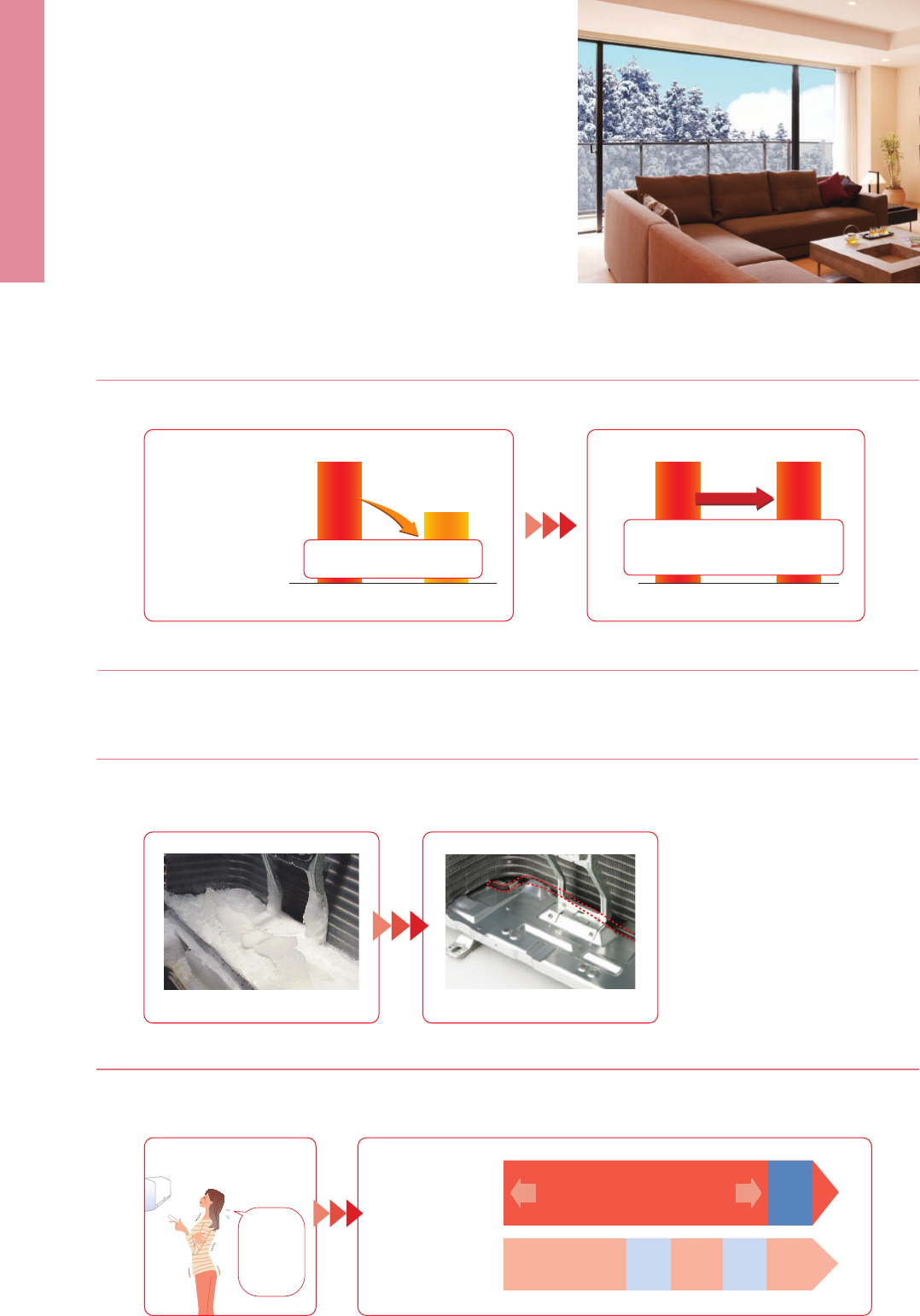
103
EXAMPLE SYSTEM Standard rated heating capacity is maintained even
when the outside-air temperature drops to –15°C.
Maintains high capacity output even when outside-air temperature is low.
MXZ-4E83VAHZ system
MSZ-FH
MSZ-EF
SLZ-KF
MFZ-KJ
Freedom of combinations in cold region greatly enhanced
The variety of indoor unit connection options in cold regions, restricted until now, has been greatly increased.
Increased design freedom.
MXZ-2E53VAHZ MXZ-4E83VAHZ
One outdoor unit supports
multiple indoor units.
With MXZ-VAHZ, one outdoor unit can cool and
heat up to six rooms. They can be installed
neatly in sites with limited space such as con-
dominium balconies.
*Please note that cooling and heating modes cannot be run
simultaneously in different rooms.
MXZ-VAHZ
SERIES
New hyper-heating MXZ allows you to create an oasis of comfort
throughout your home and office in the rooms you use most, any time
of the year.
3.0kW
6.4kW
Freeze-prevention heater standard equipment
Prevents capacity loss and operation from stopping due to drain water freezing.
Continuous heating for long periods
Wasteful defrosting operation suppressed to enable more comfortable long-term continuous heating.
Without Freeze-prevention heater With Freeze-prevention heater
OUTDOOR UNITS
2-room use 4-room use
INDOOR UNITS
Wall-mounted Floor-standing
MSZ-FH
MSZ-EF
MSZ-GF
MSZ-SF
MFZ-KJ
6.4kW
(MXZ-2E53VAHZ)(MX Z-2D53VA)
Our conventional
model was not able
to maintain standard
rated heating
capacity, making it
hard to provide
warming in case of
low outside-air
temperatures.
Falls
Maintained
Capacity decreased due to
low outdoor-air temperature
Realizes standard rating (7°C)
level heating capacity even with
outside-air temperature of -15°C.
With outside
temperature of 7°C
(standard rated heating capacity)
With outside
temperature of –15°C
With outside
temperature of 7°C
(standard rated heating capacity)
With outside
temperature of –15°C
With Zubadan
With Hyper heating
With Zubadan
Drain water freezes after operation
in the harsh cold
Extremely cold outside
Does not freeze!
Can operate at outside-air temperature of –25°C
1. Incorporated key parts resistant to cold of up to –25°C after rigorous selection.
2. Printed circuit board-core of the air conditioner — is coated on both sides to protect it in harsh environments.
MXZ-VAHZ SERIES
Conventional model
During
defrosting
operation,
the heater
stops and
is cold…
Comfort using long-term heating mode
The unit may enter defrosting mode
under certain environmental conditions,
such as if outside-air humidity increases.
Defrosting
operation
Defrosting
operation
Defrosting
operation
Heating operation
*1
Heating
operation
*1
Heating
operation
*1
*1: Conventional model performs continuous heating approximately 30min up to a maximum of 90min.
■
Single air conditioner
■
Multi air conditioner system
Clean/
Neat installation
✽1: P series cannot be connect with MXZ-4E83VAHZ when ampere limit adjustment function is operated.
Cassette Ceiling-suspended
Ceiling-concealed
SLZ-KF
PLA
MLZ-KA
PCA
SEZ-KD
PEAD
✽1
✽1
✽1
MXZ-4E83VAHZ
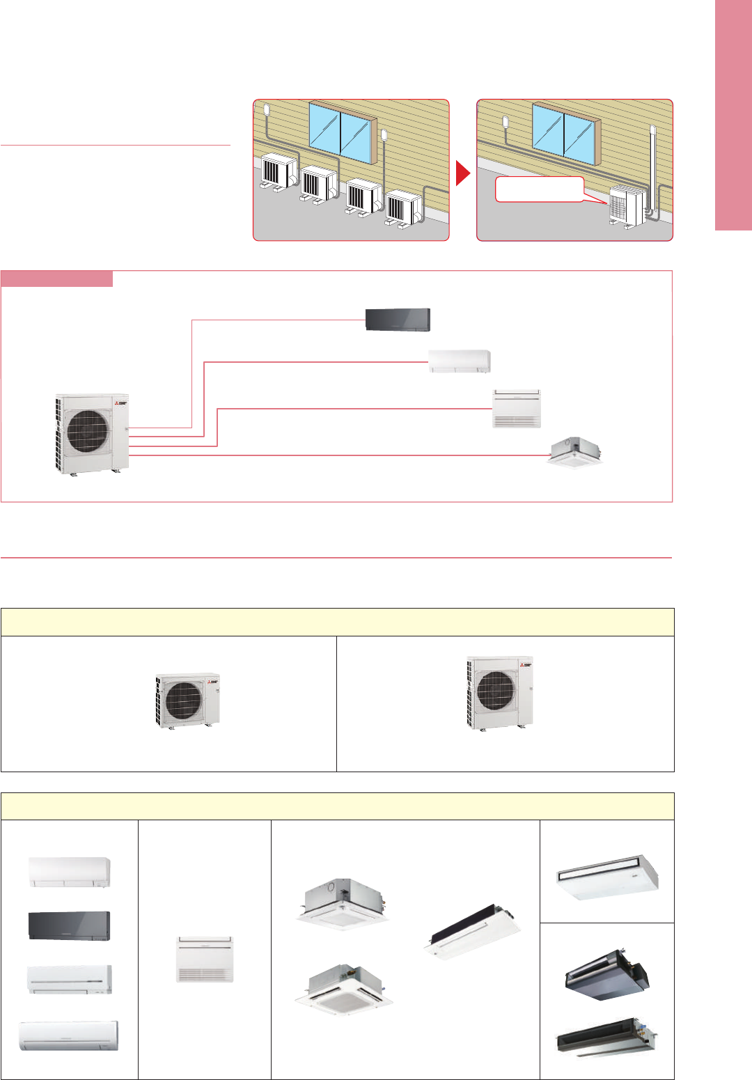
104
EXAMPLE SYSTEM Standard rated heating capacity is maintained even
when the outside-air temperature drops to –15°C.
Maintains high capacity output even when outside-air temperature is low.
MXZ-4E83VAHZ system
MSZ-FH
MSZ-EF
SLZ-KF
MFZ-KJ
Freedom of combinations in cold region greatly enhanced
The variety of indoor unit connection options in cold regions, restricted until now, has been greatly increased.
Increased design freedom.
MXZ-2E53VAHZ MXZ-4E83VAHZ
One outdoor unit supports
multiple indoor units.
With MXZ-VAHZ, one outdoor unit can cool and
heat up to six rooms. They can be installed
neatly in sites with limited space such as con-
dominium balconies.
*Please note that cooling and heating modes cannot be run
simultaneously in different rooms.
MXZ-VAHZ
SERIES
New hyper-heating MXZ allows you to create an oasis of comfort
throughout your home and office in the rooms you use most, any time
of the year.
3.0kW
6.4kW
Freeze-prevention heater standard equipment
Prevents capacity loss and operation from stopping due to drain water freezing.
Continuous heating for long periods
Wasteful defrosting operation suppressed to enable more comfortable long-term continuous heating.
Without Freeze-prevention heater With Freeze-prevention heater
OUTDOOR UNITS
2-room use 4-room use
INDOOR UNITS
Wall-mounted Floor-standing
MSZ-FH
MSZ-EF
MSZ-GF
MSZ-SF
MFZ-KJ
6.4kW
(MXZ-2E53VAHZ)(MX Z-2D53VA)
Our conventional
model was not able
to maintain standard
rated heating
capacity, making it
hard to provide
warming in case of
low outside-air
temperatures.
Falls
Maintained
Capacity decreased due to
low outdoor-air temperature
Realizes standard rating (7°C)
level heating capacity even with
outside-air temperature of -15°C.
With outside
temperature of 7°C
(standard rated heating capacity)
With outside
temperature of –15°C
With outside
temperature of 7°C
(standard rated heating capacity)
With outside
temperature of –15°C
With Zubadan
With Hyper heating
With Zubadan
Drain water freezes after operation
in the harsh cold
Extremely cold outside
Does not freeze!
Can operate at outside-air temperature of –25°C
1. Incorporated key parts resistant to cold of up to –25°C after rigorous selection.
2. Printed circuit board-core of the air conditioner — is coated on both sides to protect it in harsh environments.
MXZ-VAHZ SERIES
Conventional model
During
defrosting
operation,
the heater
stops and
is cold…
Comfort using long-term heating mode
The unit may enter defrosting mode
under certain environmental conditions,
such as if outside-air humidity increases.
Defrosting
operation
Defrosting
operation
Defrosting
operation
Heating operation
*1
Heating
operation
*1
Heating
operation
*1
*1: Conventional model performs continuous heating approximately 30min up to a maximum of 90min.
■
Single air conditioner
■
Multi air conditioner system
Clean/
Neat installation
✽1: P series cannot be connect with MXZ-4E83VAHZ when ampere limit adjustment function is operated.
Cassette Ceiling-suspended
Ceiling-concealed
SLZ-KF
PLA
MLZ-KA
PCA
SEZ-KD
PEAD
✽1
✽1
✽1
MXZ-4E83VAHZ
Outdoor UnitIndoor Unit
Standard Panel
PLP-6BA (only Panel)
PLP-6BALM (with wireless remote controller)
Automatic Filter Elevation Panel
PLP-6BAJ (only Panel)
Standard Panel with "i-see Sensor"
PLP-6BAE (only Panel)
PLP-6BALME (with wireless remote controller)
PLZ-SHW SERIES
PUHZ-SHW112VHA(-BS)
PUHZ-SHW112/140YHA(-BS)
Optional Optional Optional
100/125
OptionalOptional Optional
Optional Optional
Wi-Fi
Interface
PLA-ZRP100/125BA
Outdoor UnitIndoor Unit
Standard Panel
PLP-6BA (only Panel)
PLP-6BALM (with wireless remote controller)
Automatic Filter Elevation Panel
PLP-6BAJ (only Panel)
Standard Panel with "i-see Sensor"
PLP-6BAE (only Panel)
PLP-6BALME (with wireless remote controller)
PLZ-SHW SERIES
PUHZ-SHW112VHA(-BS)
PUHZ-SHW112/140YHA(-BS)
Optional Optional Optional
100/125
OptionalOptional Optional
Optional Optional
Wi-Fi
Interface
PLA-RP100/125BA
Inverter Heat Pump
Cooling
Heating
(Average
Season)
Operating Current (max)
Indoor
Unit
Outdoor
Unit
Ext.
Piping
Guaranteed Operating Range
[Outdoor]
Source
Outdoor (V/Phase/Hz)
Capacity
Total Input
Design Load
Annual Electricity Consumption*
2
SEER
Capacity
Total Input
Design Load
Declared Capacity
Back Up Heating Capacity
Annual Electricity Consumption*
2
SCOP
Input
Operating Current (max)
Dimensions <Panel>
Weight <Panel>
Air Volume [Lo-Mi2-Mi1-Hi]
Sound Level (SPL) [Lo-Mi2-Mi1-Hi]
Sound Level (PWL)
Dimensions
Weight
Air Volume
Sound Level (SPL)
Sound Level (PWL)
Operating Current (max)
Breaker Size
Diameter
Max. Length
Max. Height
Rated
Min - Max
Rated
Energy Efficiency Class
EER
EEL Rank
Rated
Min - Max
Rated
at reference design temperature
at bivalent temperature
at operation limit temperature
Energy Efficiency Class
COP
EEL Rank
Rated
H × W × D
H × W × D
Cooling
Heating
Cooling
Cooling
Heating
Liquid / Gas
Out-In
Out-In
Cooling*
3
Heating
kW
kW
kW
kW
kWh/a
kW
kW
kW
kW
kW
kW
kW
kW
kWh/a
kW
A
A
mm
kg
m
3
/min
dB(A)
dB(A)
mm
kg
m
3
/min
m
3
/min
dB(A)
dB(A)
dB(A)
A
A
mm
m
m
o
C
o
C
PLA-ZRP100BA PLA-ZRP125BA
PUHZ-SHW112VHA(-BS) PUHZ-SHW112YHA(-BS) PUHZ-SHW140YHA(-BS)
*1 Refrigerant leakage contributes to climate change. Refrigerant with lower global warming potential (GWP) would contribute less to global warming than a refrigerant with higher GWP, if leaked to the atmosphere.
This appliance contains a refrigerant fluid with a GWP equal to 1975. This means that if 1kg of this refrigerant fluid would be leaked to the atmosphere, the impact on global warming would be 1975 times higher
than 1kg of CO2, over a period of 100 years. Never try to interfere with the refrigerant circuit yourself or disassemble the product yourself and always ask a professional.
*2 Energy consumption based on standard test results. Actual energy consumption will depend on how the appliance is used and where it is located.
*3 Optional air protection guide is required where ambient temperature is lower than –5°C.
*4 SEER/SCOP values are measured based on EN14825. These values are reference purpose only.
Type
Indoor Unit
Outdoor Unit
Refrigerant
Power
Supply
R410A*
1
Outdoor power supply
VHA:230 / Single / 50, YHA:400 / Three / 50
R410A*
1
Outdoor power supply
VHA:230 / Single / 50, YHA:400 / Three / 50
10.0
4.9 - 11.4
2.786
–
–
10.0
633
5.5
A
11.2
4.5 - 14.0
2.667
–
–
12.7
11.2
11.2
9.4
1.5
4420
4.0
A
+
35.7
0.08
0.74
26 <6>
20 - 23 - 26 - 30
32 - 34 - 37 - 40
65
120
100.0
100.0
51
52
69
35.0
40
9.52 / 15.88
75
30
–15 ~ +46
–25 ~ +21
10.0
4.9 - 11.4
2.786
–
–
10.0
633
5.5
A
11.2
4.5 - 14.0
2.667
–
–
12.7
11.2
11.2
9.4
1.5
4420
4.0
A
+
13.7
0.08
0.74
26 <6>
20 - 23 - 26 - 30
32 - 34 - 37 - 40
65
134
100.0
100.0
51
52
69
13.0
16
9.52 / 15.88
75
30
–15 ~ +46
–25 ~ +21
12.5
5.5 - 14.0
4.449
2.81
–
12.5
856
5.1*
4
–
14.0
5.0 - 16.0
3.879
3.61
–
15.8
14.0
14.0
9.5
1.8
6213
3.5*
4
–
13.8
0.09
0.80
27 <6>
22 - 25 - 28 - 31
34 - 36 - 39 - 41
66
134
100.0
100.0
51
52
69
13.0
16
9.52 / 15.88
75
30
–15 ~ +46
–25 ~ +21
Inverter Heat Pump
Cooling
Heating
(Average
Season)
Operating Current (max)
Indoor
Unit
Outdoor
Unit
Ext.
Piping
Guaranteed Operating Range
[Outdoor]
Source
Outdoor (V/Phase/Hz)
Capacity
Total Input
Design Load
Annual Electricity Consumption*
2
SEER
Capacity
Total Input
Design Load
Declared Capacity
Back Up Heating Capacity
Annual Electricity Consumption*
2
SCOP
Input
Operating Current (max)
Dimensions <Panel>
Weight <Panel>
Air Volume [Lo-Mi2-Mi1-Hi]
Sound Level (SPL) [Lo-Mi2-Mi1-Hi]
Sound Level (PWL)
Dimensions
Weight
Air Volume
Sound Level (SPL)
Sound Level (PWL)
Operating Current (max)
Breaker Size
Diameter
Max. Length
Max. Height
Rated
Min - Max
Rated
Energy Efficiency Class
EER
EEL Rank
Rated
Min - Max
Rated
at reference design temperature
at bivalent temperature
at operation limit temperature
Energy Efficiency Class
COP
EEL Rank
Rated
H × W × D
H × W × D
Cooling
Heating
Cooling
Cooling
Heating
Liquid / Gas
Out-In
Out-In
Cooling*
3
Heating
kW
kW
kW
kW
kWh/a
kW
kW
kW
kW
kW
kW
kW
kW
kWh/a
kW
A
A
mm
kg
m
3
/min
dB(A)
dB(A)
mm
kg
m
3
/min
m
3
/min
dB(A)
dB(A)
dB(A)
A
A
mm
m
m
o
C
o
C
PLA-RP100BA PLA-RP125BA
PUHZ-SHW112VHA(-BS) PUHZ-SHW112YHA(-BS) PUHZ-SHW140YHA(-BS)
*1 Refrigerant leakage contributes to climate change. Refrigerant with lower global warming potential (GWP) would contribute less to global warming than a refrigerant with higher GWP, if leaked to the atmosphere.
This appliance contains a refrigerant fluid with a GWP equal to 1975. This means that if 1kg of this refrigerant fluid would be leaked to the atmosphere, the impact on global warming would be 1975 times higher
than 1kg of CO2, over a period of 100 years. Never try to interfere with the refrigerant circuit yourself or disassemble the product yourself and always ask a professional.
*2 Energy consumption based on standard test results. Actual energy consumption will depend on how the appliance is used and where it is located.
*3 Optional air protection guide is required where ambient temperature is lower than –5°C.
*4 SEER/SCOP values are measured based on EN14825. These values are reference purpose only.
Type
Indoor Unit
Outdoor Unit
Refrigerant
Power
Supply
10.0
4.9 - 11.4
2.850
–
–
10.0
661
5.3
A
11.2
4.5 - 14.0
2.794
–
–
12.7
11.2
11.2
9.4
1.5
4445
4.0
A
+
35.7
0.14
0.94
25 <6>
20 - 23 - 26 - 30
32 - 34 - 37 - 40
62
120
100.0
100.0
51
52
69
35.0
40
9.52 / 15.88
75
30
–15 ~ +46
–25 ~ +21
10.0
4.9 - 11.4
2.850
–
–
10.0
661
5.3
A
11.2
4.5 - 14.0
2.794
–
–
12.7
11.2
11.2
9.4
1.5
4445
4.0
A
+
13.7
0.14
0.94
298-840-840 <35-950-950>
25 <6>
20 - 23 - 26 - 30
32 - 34 - 37 - 40
62
134
100.0
100.0
51
52
69
13.0
16
9.52 / 15.88
75
30
–15 ~ +46
–25 ~ +21
12.5
5.5 - 14.0
4.449
2.81
–
12.5
858
5.1*
4
–
14.0
5.0 - 16.0
3.879
3.61
–
15.8
14.0
14.0
9.5
1.8
6506
3.4*
4
–
13.8
0.15
1.00
25 <6>
22 - 25 - 28 - 31
34 - 36 - 39 - 41
63
134
100.0
100.0
51
52
69
13.0
16
9.52 / 15.88
75
30
–15 ~ +46
–25 ~ +21
298 - 840 - 840 <35-950-950>
1350 - 950 - 330 (+30)
1350 - 950 - 330 (+30)
*optional
*optional
Remote Controller
Enclosed in
PLP-6BALM/PLP-6BALME
*optional
*optional
Remote Controller
Enclosed in
PLP-6BALM/PLP-6BALME
Please fill out the requested information
Please fill out the requested information
105
Outdoor UnitIndoor Unit
Standard Panel
PLP-6BA (only Panel)
PLP-6BALM (with wireless remote controller)
Automatic Filter Elevation Panel
PLP-6BAJ (only Panel)
Standard Panel with "i-see Sensor"
PLP-6BAE (only Panel)
PLP-6BALME (with wireless remote controller)
PLZ-SHW SERIES
PUHZ-SHW112VHA(-BS)
PUHZ-SHW112/140YHA(-BS)
Optional Optional Optional
100/125
OptionalOptional Optional
Optional Optional
Wi-Fi
Interface
PLA-ZRP100/125BA
Outdoor UnitIndoor Unit
Standard Panel
PLP-6BA (only Panel)
PLP-6BALM (with wireless remote controller)
Automatic Filter Elevation Panel
PLP-6BAJ (only Panel)
Standard Panel with "i-see Sensor"
PLP-6BAE (only Panel)
PLP-6BALME (with wireless remote controller)
PLZ-SHW SERIES
PUHZ-SHW112VHA(-BS)
PUHZ-SHW112/140YHA(-BS)
Optional Optional Optional
100/125
OptionalOptional Optional
Optional Optional
Wi-Fi
Interface
PLA-RP100/125BA
Inverter Heat Pump
Cooling
Heating
(Average
Season)
Operating Current (max)
Indoor
Unit
Outdoor
Unit
Ext.
Piping
Guaranteed Operating Range
[Outdoor]
Source
Outdoor (V/Phase/Hz)
Capacity
Total Input
Design Load
Annual Electricity Consumption*
2
SEER
Capacity
Total Input
Design Load
Declared Capacity
Back Up Heating Capacity
Annual Electricity Consumption*
2
SCOP
Input
Operating Current (max)
Dimensions <Panel>
Weight <Panel>
Air Volume [Lo-Mi2-Mi1-Hi]
Sound Level (SPL) [Lo-Mi2-Mi1-Hi]
Sound Level (PWL)
Dimensions
Weight
Air Volume
Sound Level (SPL)
Sound Level (PWL)
Operating Current (max)
Breaker Size
Diameter
Max. Length
Max. Height
Rated
Min - Max
Rated
Energy Efficiency Class
EER
EEL Rank
Rated
Min - Max
Rated
at reference design temperature
at bivalent temperature
at operation limit temperature
Energy Efficiency Class
COP
EEL Rank
Rated
H × W × D
H × W × D
Cooling
Heating
Cooling
Cooling
Heating
Liquid / Gas
Out-In
Out-In
Cooling*
3
Heating
kW
kW
kW
kW
kWh/a
kW
kW
kW
kW
kW
kW
kW
kW
kWh/a
kW
A
A
mm
kg
m
3
/min
dB(A)
dB(A)
mm
kg
m
3
/min
m
3
/min
dB(A)
dB(A)
dB(A)
A
A
mm
m
m
o
C
o
C
PLA-ZRP100BA PLA-ZRP125BA
PUHZ-SHW112VHA(-BS) PUHZ-SHW112YHA(-BS) PUHZ-SHW140YHA(-BS)
*1 Refrigerant leakage contributes to climate change. Refrigerant with lower global warming potential (GWP) would contribute less to global warming than a refrigerant with higher GWP, if leaked to the atmosphere.
This appliance contains a refrigerant fluid with a GWP equal to 1975. This means that if 1kg of this refrigerant fluid would be leaked to the atmosphere, the impact on global warming would be 1975 times higher
than 1kg of CO2, over a period of 100 years. Never try to interfere with the refrigerant circuit yourself or disassemble the product yourself and always ask a professional.
*2 Energy consumption based on standard test results. Actual energy consumption will depend on how the appliance is used and where it is located.
*3 Optional air protection guide is required where ambient temperature is lower than –5°C.
*4 SEER/SCOP values are measured based on EN14825. These values are reference purpose only.
Type
Indoor Unit
Outdoor Unit
Refrigerant
Power
Supply
R410A*
1
Outdoor power supply
VHA:230 / Single / 50, YHA:400 / Three / 50
R410A*
1
Outdoor power supply
VHA:230 / Single / 50, YHA:400 / Three / 50
10.0
4.9 - 11.4
2.786
–
–
10.0
633
5.5
A
11.2
4.5 - 14.0
2.667
–
–
12.7
11.2
11.2
9.4
1.5
4420
4.0
A
+
35.7
0.08
0.74
26 <6>
20 - 23 - 26 - 30
32 - 34 - 37 - 40
65
120
100.0
100.0
51
52
69
35.0
40
9.52 / 15.88
75
30
–15 ~ +46
–25 ~ +21
10.0
4.9 - 11.4
2.786
–
–
10.0
633
5.5
A
11.2
4.5 - 14.0
2.667
–
–
12.7
11.2
11.2
9.4
1.5
4420
4.0
A
+
13.7
0.08
0.74
26 <6>
20 - 23 - 26 - 30
32 - 34 - 37 - 40
65
134
100.0
100.0
51
52
69
13.0
16
9.52 / 15.88
75
30
–15 ~ +46
–25 ~ +21
12.5
5.5 - 14.0
4.449
2.81
–
12.5
856
5.1*
4
–
14.0
5.0 - 16.0
3.879
3.61
–
15.8
14.0
14.0
9.5
1.8
6213
3.5*
4
–
13.8
0.09
0.80
27 <6>
22 - 25 - 28 - 31
34 - 36 - 39 - 41
66
134
100.0
100.0
51
52
69
13.0
16
9.52 / 15.88
75
30
–15 ~ +46
–25 ~ +21
Inverter Heat Pump
Cooling
Heating
(Average
Season)
Operating Current (max)
Indoor
Unit
Outdoor
Unit
Ext.
Piping
Guaranteed Operating Range
[Outdoor]
Source
Outdoor (V/Phase/Hz)
Capacity
Total Input
Design Load
Annual Electricity Consumption*
2
SEER
Capacity
Total Input
Design Load
Declared Capacity
Back Up Heating Capacity
Annual Electricity Consumption*
2
SCOP
Input
Operating Current (max)
Dimensions <Panel>
Weight <Panel>
Air Volume [Lo-Mi2-Mi1-Hi]
Sound Level (SPL) [Lo-Mi2-Mi1-Hi]
Sound Level (PWL)
Dimensions
Weight
Air Volume
Sound Level (SPL)
Sound Level (PWL)
Operating Current (max)
Breaker Size
Diameter
Max. Length
Max. Height
Rated
Min - Max
Rated
Energy Efficiency Class
EER
EEL Rank
Rated
Min - Max
Rated
at reference design temperature
at bivalent temperature
at operation limit temperature
Energy Efficiency Class
COP
EEL Rank
Rated
H × W × D
H × W × D
Cooling
Heating
Cooling
Cooling
Heating
Liquid / Gas
Out-In
Out-In
Cooling*
3
Heating
kW
kW
kW
kW
kWh/a
kW
kW
kW
kW
kW
kW
kW
kW
kWh/a
kW
A
A
mm
kg
m
3
/min
dB(A)
dB(A)
mm
kg
m
3
/min
m
3
/min
dB(A)
dB(A)
dB(A)
A
A
mm
m
m
o
C
o
C
PLA-RP100BA PLA-RP125BA
PUHZ-SHW112VHA(-BS) PUHZ-SHW112YHA(-BS) PUHZ-SHW140YHA(-BS)
*1 Refrigerant leakage contributes to climate change. Refrigerant with lower global warming potential (GWP) would contribute less to global warming than a refrigerant with higher GWP, if leaked to the atmosphere.
This appliance contains a refrigerant fluid with a GWP equal to 1975. This means that if 1kg of this refrigerant fluid would be leaked to the atmosphere, the impact on global warming would be 1975 times higher
than 1kg of CO2, over a period of 100 years. Never try to interfere with the refrigerant circuit yourself or disassemble the product yourself and always ask a professional.
*2 Energy consumption based on standard test results. Actual energy consumption will depend on how the appliance is used and where it is located.
*3 Optional air protection guide is required where ambient temperature is lower than –5°C.
*4 SEER/SCOP values are measured based on EN14825. These values are reference purpose only.
Type
Indoor Unit
Outdoor Unit
Refrigerant
Power
Supply
10.0
4.9 - 11.4
2.850
–
–
10.0
661
5.3
A
11.2
4.5 - 14.0
2.794
–
–
12.7
11.2
11.2
9.4
1.5
4445
4.0
A
+
35.7
0.14
0.94
25 <6>
20 - 23 - 26 - 30
32 - 34 - 37 - 40
62
120
100.0
100.0
51
52
69
35.0
40
9.52 / 15.88
75
30
–15 ~ +46
–25 ~ +21
10.0
4.9 - 11.4
2.850
–
–
10.0
661
5.3
A
11.2
4.5 - 14.0
2.794
–
–
12.7
11.2
11.2
9.4
1.5
4445
4.0
A
+
13.7
0.14
0.94
298-840-840 <35-950-950>
25 <6>
20 - 23 - 26 - 30
32 - 34 - 37 - 40
62
134
100.0
100.0
51
52
69
13.0
16
9.52 / 15.88
75
30
–15 ~ +46
–25 ~ +21
12.5
5.5 - 14.0
4.449
2.81
–
12.5
858
5.1*
4
–
14.0
5.0 - 16.0
3.879
3.61
–
15.8
14.0
14.0
9.5
1.8
6506
3.4*
4
–
13.8
0.15
1.00
25 <6>
22 - 25 - 28 - 31
34 - 36 - 39 - 41
63
134
100.0
100.0
51
52
69
13.0
16
9.52 / 15.88
75
30
–15 ~ +46
–25 ~ +21
298 - 840 - 840 <35-950-950>
1350 - 950 - 330 (+30)
1350 - 950 - 330 (+30)
*optional
*optional
Remote Controller
Enclosed in
PLP-6BALM/PLP-6BALME
*optional
*optional
Remote Controller
Enclosed in
PLP-6BALM/PLP-6BALME
Please fill out the requested information
Please fill out the requested information
106
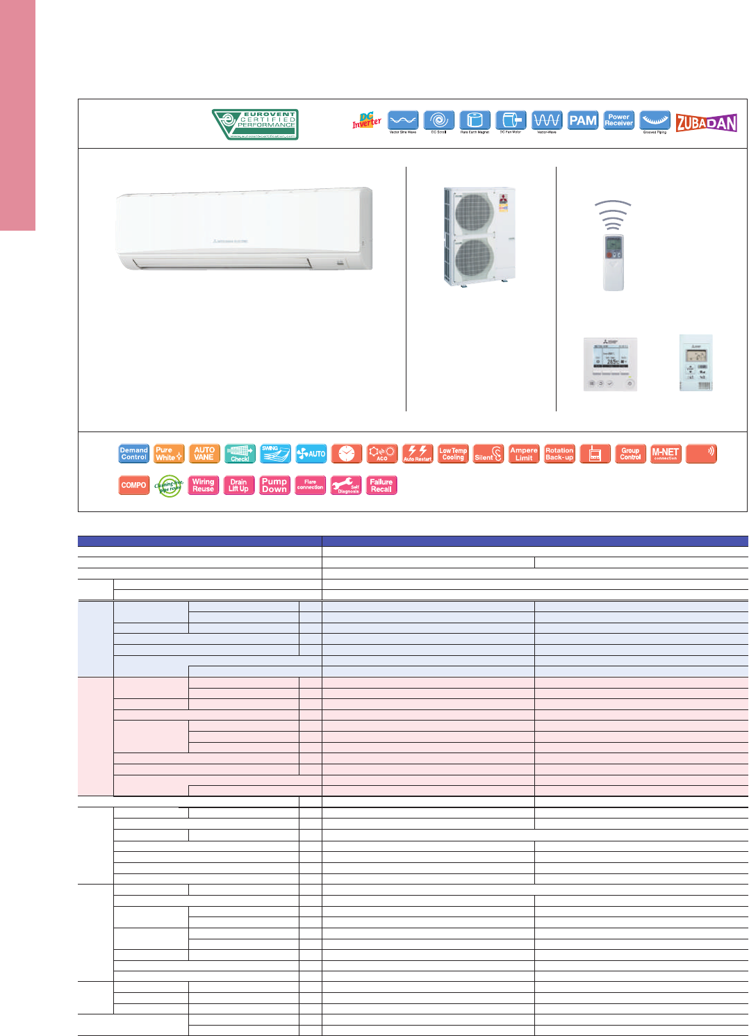
PUHZ-SHW112VHA(-BS)
PUHZ-SHW112/140YHA(-BS)
Outdoor Unit
Indoor Unit
PKZ-SHW SERIES
Optional
Optional Optional Optional
Optional
Optional
Optional
Optional Optional
PKA-RP100KAL
*optional
*optional
Remote Controller
Please fill out the requested information
Please fill out the requested information
*optional
*optional
*optional
Indoor Unit
PEDZ-SHW JA SERIES
Outdoor Unit
PUHZ-SHW112VHA(-BS)
PUHZ-SHW112/140YHA(-BS)
Optional
100/125
OptionalOptional
Optional
JAQ
Optional Optional
PEAD-RP100/125JA(L)Q
Remote Controller
Please fill out the requested information
Please fill out the requested information
R410A*
1
Outdoor power supply
VHA:230 / Single / 50, YHA:400 / Three / 50
Inverter Heat Pump
Cooling
Heating
(Average
Season)
Operating Current (max)
Indoor
Unit
Outdoor
Unit
Ext.
Piping
Guaranteed Operating Range
[Outdoor]
Source
Outdoor (V/Phase/Hz)
Capacity
Total Input
Design Load
Annual Electricity Consumption*
2
SEER
Capacity
Total Input
Design Load
Declared Capacity
Back Up Heating Capacity
Annual Electricity Consumption*
2
SCOP
Input [Cooling / Heating]
Operating Current (max)
Dimensions
Weight
Air Volume [Lo-Mid-Hi]
Sound Level (SPL) [Lo-Mid-Hi]
Sound Level (PWL)
Dimensions
Weight
Air Volume
Sound Level (SPL)
Sound Level (PWL)
Operating Current (max)
Breaker Size
Diameter
Max. Length
Max. Height
Rated
Min - Max
Rated
Energy Efficiency Class
EER
EEL Rank
Rated
Min - Max
Rated
at reference design temperature
at bivalent temperature
at operation limit temperature
Energy Efficiency Class
COP
EEL Rank
Rated
H × W × D
H × W × D
Cooling
Heating
Cooling
Cooling
Heating
Liquid / Gas
Out-In
Out-In
Cooling*
3
Heating
kW
kW
kW
kW
kWh/a
kW
kW
kW
kW
kW
kW
kW
kW
kWh/a
kW
A
A
mm
kg
m
3
/min
dB(A)
External Static Pressure
Pa
dB(A)
mm
kg
m
3
/min
m
3
/min
dB(A)
dB(A)
dB(A)
A
A
mm
m
m
o
C
o
C
PEAD-RP100JA(L)Q PEAD-RP125JA(L)Q
PUHZ-SHW112VHA(-BS) PUHZ-SHW112YHA(-BS) PUHZ-SHW140YHA(-BS)
*1 Refrigerant leakage contributes to climate change. Refrigerant with lower global warming potential (GWP) would contribute less to global warming than a refrigerant with higher GWP, if leaked to the atmosphere.
This appliance contains a refrigerant fluid with a GWP equal to 1975. This means that if 1kg of this refrigerant fluid would be leaked to the atmosphere, the impact on global warming would be 1975 times higher
than 1kg of CO2, over a period of 100 years. Never try to interfere with the refrigerant circuit yourself or disassemble the product yourself and always ask a professional.
*2 Energy consumption based on standard test results. Actual energy consumption will depend on how the appliance is used and where it is located.
*3 Optional air protection guide is required where ambient temperature is lower than –5°C.
*4 SEER/SCOP values are measured based on EN14825. These values are reference purpose only.
Type
Indoor Unit
Outdoor Unit
Refrigerant
Power
Supply
R410A*
1
Outdoor power supply
VHA:230 / Single / 50, YHA:400 / Three / 50
Inverter Heat Pump
Cooling
Heating
(Average
Season)
Operating Current (max)
Indoor
Unit
Outdoor
Unit
Ext.
Piping
Guaranteed Operating Range
[Outdoor]
Source
Outdoor (V/Phase/Hz)
Capacity
Total Input
Design Load
Annual Electricity Consumption*
2
SEER
Capacity
Total Input
Design Load
Declared Capacity
Back Up Heating Capacity
Annual Electricity Consumption*
2
SCOP
Input
Operating Current (max)
Dimensions <Panel>
Weight <Panel>
Air Volume [Lo-Mid-Hi]
Sound Level (SPL) [Lo-Mid-Hi]
Sound Level (PWL)
Dimensions
Weight
Air Volume
Sound Level (SPL)
Sound Level (PWL)
Operating Current (max)
Breaker Size
Diameter
Max. Length
Max. Height
Rated
Min - Max
Rated
Energy Efficiency Class
Rated
Min - Max
Rated
at reference design temperature
at bivalent temperature
at operation limit temperature
Energy Efficiency Class
Rated
H × W × D
H × W × D
Cooling
Heating
Cooling
Cooling
Heating
Liquid / Gas
Out-In
Out-In
Cooling*
3
Heating
kW
kW
kW
kW
kWh/a
kW
kW
kW
kW
kW
kW
kW
kW
kWh/a
kW
A
A
mm
kg
m
3
/min
dB(A)
dB(A)
mm
kg
m
3
/min
m
3
/min
dB(A)
dB(A)
dB(A)
A
A
mm
m
m
o
C
o
C
PKA-RP100KAL
PUHZ-SHW112VHA(-BS) PUHZ-SHW112YHA(-BS)
*1 Refrigerant leakage contributes to climate change. Refrigerant with lower global warming potential (GWP) would contribute less to global warming than a refrigerant with higher GWP, if leaked to the atmosphere.
This appliance contains a refrigerant fluid with a GWP equal to 1975. This means that if 1kg of this refrigerant fluid would be leaked to the atmosphere, the impact on global warming would be 1975 times higher
than 1kg of CO2
, over a period of 100 years. Never try to interfere with the refrigerant circuit yourself or disassemble the product yourself and always ask a professional.
*2 Energy consumption based on standard test results. Actual energy consumption will depend on how the appliance is used and where it is located.
*3 Optional air protection guide is required where ambient temperature is lower than –5°C.
Type
Indoor Unit
Outdoor Unit
Refrigerant
Power
Supply
10.0
4.9 - 11.4
2.924
10.0
673
5.2
A
11.2
4.5 - 14.0
3.103
12.7
11.2
11.2
9.4
1.5
4664
3.8
A
35.6
0.08
0.57
21
20 - 23 - 26
41 - 45 - 49
65
120
100.0
100.0
51
52
69
35.0
40
9.52 / 15.88
75
30
–15 ~ +46
–25 ~ +21
10.0
4.9 - 11.4
2.924
10.0
673
5.2
A
11.2
4.5 - 14.0
3.103
12.7
11.2
11.2
9.4
1.5
4664
3.8
A
13.6
0.08
0.57
21
20 - 23 - 26
41 - 45 - 49
65
134
100.0
100.0
51
52
69
13.0
16
9.52 / 15.88
75
30
–15 ~ +46
–25 ~ +21
10.0
4.9 - 11.4
2.924 (2.904)
–
–
10.0
729 (714)
4.8 (4.9)
B
11.2
4.5 - 14.0
3.103
–
–
12.7
11.2
11.2
9.4
1.5
4664
3.8
A
37.7
0.25 (0.23) / 0.23
2.65
41 (40)
24.0 - 29.0 - 34.0
35 / 50 / 70 / 100 / 150
29 - 34 - 38
61
120
100.0
100.0
51
52
69
35.0
40
9.52 / 15.88
75
30
–15 ~ +46
–25 ~ +21
10.0
4.9 - 11.4
2.924 (2.904)
–
–
10.0
729 (714)
4.8 (4.9)
B
11.2
4.5 - 14.0
3.103
–
–
12.7
11.2
11.2
9.4
1.5
4664
3.8
A
15.7
0.25 (0.23) / 0.23
2.65
250 - 1400 - 732
41 (40)
24.0 - 29.0 - 34.0
35 / 50 / 70 / 100 / 150
29 - 34 - 38
61
134
100.0
100.0
51
52
69
13.0
16
9.52 / 15.88
75
30
–15 ~ +46
–25 ~ +21
12.5
5.5 - 14.0
3.895 (3.875)
3.21 (3.22)
–
12.5
906 (892)
4.8 (4.9)*
4
–
14.0
5.0 - 16.0
3.879
3.61
–
15.8
14.0
14.0
9.5
1.8
6072
3.6*
4
–
15.8
0.36 (0.34) / 0.34
2.76
43 (42)
29.5 - 35.5 - 42.0
35 / 50 / 70 / 100 / 150
33 - 36 - 40
65
134
100.0
100.0
51
52
69
13.0
16
9.52 / 15.88
75
30
–15 ~ +46
–25 ~ +21
365 - 1170 - 295
1350 - 950 - 330 (+30)
1350 - 950 - 330 (+30)
Wi-Fi
Interface
Wi-Fi
Interface
107
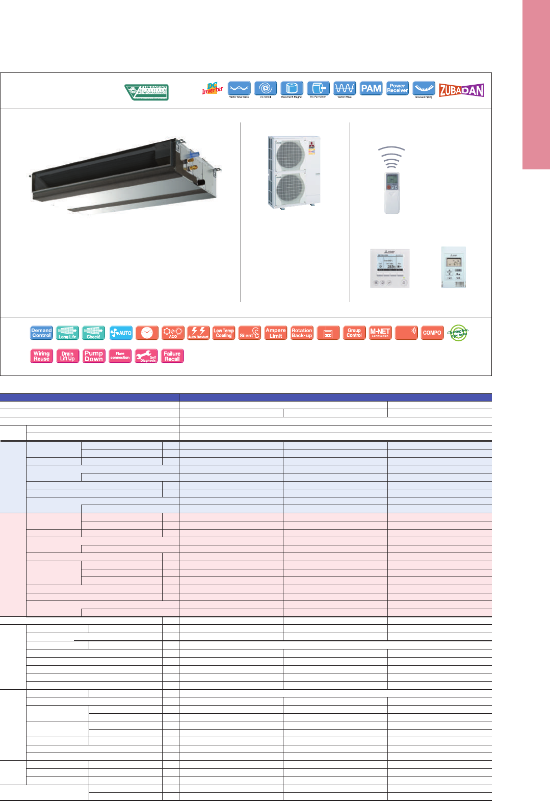
PUHZ-SHW112VHA(-BS)
PUHZ-SHW112/140YHA(-BS)
Outdoor Unit
Indoor Unit
PKZ-SHW SERIES
Optional
Optional Optional Optional
Optional
Optional
Optional
Optional Optional
PKA-RP100KAL
*optional
*optional
Remote Controller
Please fill out the requested information
Please fill out the requested information
*optional
*optional
*optional
Indoor Unit
PEDZ-SHW JA SERIES
Outdoor Unit
PUHZ-SHW112VHA(-BS)
PUHZ-SHW112/140YHA(-BS)
Optional
100/125
OptionalOptional
Optional
JAQ
Optional Optional
PEAD-RP100/125JA(L)Q
Remote Controller
Please fill out the requested information
Please fill out the requested information
R410A*
1
Outdoor power supply
VHA:230 / Single / 50, YHA:400 / Three / 50
Inverter Heat Pump
Cooling
Heating
(Average
Season)
Operating Current (max)
Indoor
Unit
Outdoor
Unit
Ext.
Piping
Guaranteed Operating Range
[Outdoor]
Source
Outdoor (V/Phase/Hz)
Capacity
Total Input
Design Load
Annual Electricity Consumption*
2
SEER
Capacity
Total Input
Design Load
Declared Capacity
Back Up Heating Capacity
Annual Electricity Consumption*
2
SCOP
Input [Cooling / Heating]
Operating Current (max)
Dimensions
Weight
Air Volume [Lo-Mid-Hi]
Sound Level (SPL) [Lo-Mid-Hi]
Sound Level (PWL)
Dimensions
Weight
Air Volume
Sound Level (SPL)
Sound Level (PWL)
Operating Current (max)
Breaker Size
Diameter
Max. Length
Max. Height
Rated
Min - Max
Rated
Energy Efficiency Class
EER
EEL Rank
Rated
Min - Max
Rated
at reference design temperature
at bivalent temperature
at operation limit temperature
Energy Efficiency Class
COP
EEL Rank
Rated
H × W × D
H × W × D
Cooling
Heating
Cooling
Cooling
Heating
Liquid / Gas
Out-In
Out-In
Cooling*
3
Heating
kW
kW
kW
kW
kWh/a
kW
kW
kW
kW
kW
kW
kW
kW
kWh/a
kW
A
A
mm
kg
m
3
/min
dB(A)
External Static Pressure
Pa
dB(A)
mm
kg
m
3
/min
m
3
/min
dB(A)
dB(A)
dB(A)
A
A
mm
m
m
o
C
o
C
PEAD-RP100JA(L)Q PEAD-RP125JA(L)Q
PUHZ-SHW112VHA(-BS) PUHZ-SHW112YHA(-BS) PUHZ-SHW140YHA(-BS)
*1 Refrigerant leakage contributes to climate change. Refrigerant with lower global warming potential (GWP) would contribute less to global warming than a refrigerant with higher GWP, if leaked to the atmosphere.
This appliance contains a refrigerant fluid with a GWP equal to 1975. This means that if 1kg of this refrigerant fluid would be leaked to the atmosphere, the impact on global warming would be 1975 times higher
than 1kg of CO2, over a period of 100 years. Never try to interfere with the refrigerant circuit yourself or disassemble the product yourself and always ask a professional.
*2 Energy consumption based on standard test results. Actual energy consumption will depend on how the appliance is used and where it is located.
*3 Optional air protection guide is required where ambient temperature is lower than –5°C.
*4 SEER/SCOP values are measured based on EN14825. These values are reference purpose only.
Type
Indoor Unit
Outdoor Unit
Refrigerant
Power
Supply
R410A*
1
Outdoor power supply
VHA:230 / Single / 50, YHA:400 / Three / 50
Inverter Heat Pump
Cooling
Heating
(Average
Season)
Operating Current (max)
Indoor
Unit
Outdoor
Unit
Ext.
Piping
Guaranteed Operating Range
[Outdoor]
Source
Outdoor (V/Phase/Hz)
Capacity
Total Input
Design Load
Annual Electricity Consumption*
2
SEER
Capacity
Total Input
Design Load
Declared Capacity
Back Up Heating Capacity
Annual Electricity Consumption*
2
SCOP
Input
Operating Current (max)
Dimensions <Panel>
Weight <Panel>
Air Volume [Lo-Mid-Hi]
Sound Level (SPL) [Lo-Mid-Hi]
Sound Level (PWL)
Dimensions
Weight
Air Volume
Sound Level (SPL)
Sound Level (PWL)
Operating Current (max)
Breaker Size
Diameter
Max. Length
Max. Height
Rated
Min - Max
Rated
Energy Efficiency Class
Rated
Min - Max
Rated
at reference design temperature
at bivalent temperature
at operation limit temperature
Energy Efficiency Class
Rated
H × W × D
H × W × D
Cooling
Heating
Cooling
Cooling
Heating
Liquid / Gas
Out-In
Out-In
Cooling*
3
Heating
kW
kW
kW
kW
kWh/a
kW
kW
kW
kW
kW
kW
kW
kW
kWh/a
kW
A
A
mm
kg
m
3
/min
dB(A)
dB(A)
mm
kg
m
3
/min
m
3
/min
dB(A)
dB(A)
dB(A)
A
A
mm
m
m
o
C
o
C
PKA-RP100KAL
PUHZ-SHW112VHA(-BS) PUHZ-SHW112YHA(-BS)
*1 Refrigerant leakage contributes to climate change. Refrigerant with lower global warming potential (GWP) would contribute less to global warming than a refrigerant with higher GWP, if leaked to the atmosphere.
This appliance contains a refrigerant fluid with a GWP equal to 1975. This means that if 1kg of this refrigerant fluid would be leaked to the atmosphere, the impact on global warming would be 1975 times higher
than 1kg of CO2
, over a period of 100 years. Never try to interfere with the refrigerant circuit yourself or disassemble the product yourself and always ask a professional.
*2 Energy consumption based on standard test results. Actual energy consumption will depend on how the appliance is used and where it is located.
*3 Optional air protection guide is required where ambient temperature is lower than –5°C.
Type
Indoor Unit
Outdoor Unit
Refrigerant
Power
Supply
10.0
4.9 - 11.4
2.924
10.0
673
5.2
A
11.2
4.5 - 14.0
3.103
12.7
11.2
11.2
9.4
1.5
4664
3.8
A
35.6
0.08
0.57
21
20 - 23 - 26
41 - 45 - 49
65
120
100.0
100.0
51
52
69
35.0
40
9.52 / 15.88
75
30
–15 ~ +46
–25 ~ +21
10.0
4.9 - 11.4
2.924
10.0
673
5.2
A
11.2
4.5 - 14.0
3.103
12.7
11.2
11.2
9.4
1.5
4664
3.8
A
13.6
0.08
0.57
21
20 - 23 - 26
41 - 45 - 49
65
134
100.0
100.0
51
52
69
13.0
16
9.52 / 15.88
75
30
–15 ~ +46
–25 ~ +21
10.0
4.9 - 11.4
2.924 (2.904)
–
–
10.0
729 (714)
4.8 (4.9)
B
11.2
4.5 - 14.0
3.103
–
–
12.7
11.2
11.2
9.4
1.5
4664
3.8
A
37.7
0.25 (0.23) / 0.23
2.65
41 (40)
24.0 - 29.0 - 34.0
35 / 50 / 70 / 100 / 150
29 - 34 - 38
61
120
100.0
100.0
51
52
69
35.0
40
9.52 / 15.88
75
30
–15 ~ +46
–25 ~ +21
10.0
4.9 - 11.4
2.924 (2.904)
–
–
10.0
729 (714)
4.8 (4.9)
B
11.2
4.5 - 14.0
3.103
–
–
12.7
11.2
11.2
9.4
1.5
4664
3.8
A
15.7
0.25 (0.23) / 0.23
2.65
250 - 1400 - 732
41 (40)
24.0 - 29.0 - 34.0
35 / 50 / 70 / 100 / 150
29 - 34 - 38
61
134
100.0
100.0
51
52
69
13.0
16
9.52 / 15.88
75
30
–15 ~ +46
–25 ~ +21
12.5
5.5 - 14.0
3.895 (3.875)
3.21 (3.22)
–
12.5
906 (892)
4.8 (4.9)*
4
–
14.0
5.0 - 16.0
3.879
3.61
–
15.8
14.0
14.0
9.5
1.8
6072
3.6*
4
–
15.8
0.36 (0.34) / 0.34
2.76
43 (42)
29.5 - 35.5 - 42.0
35 / 50 / 70 / 100 / 150
33 - 36 - 40
65
134
100.0
100.0
51
52
69
13.0
16
9.52 / 15.88
75
30
–15 ~ +46
–25 ~ +21
365 - 1170 - 295
1350 - 950 - 330 (+30)
1350 - 950 - 330 (+30)
Wi-Fi
Interface
Wi-Fi
Interface
108
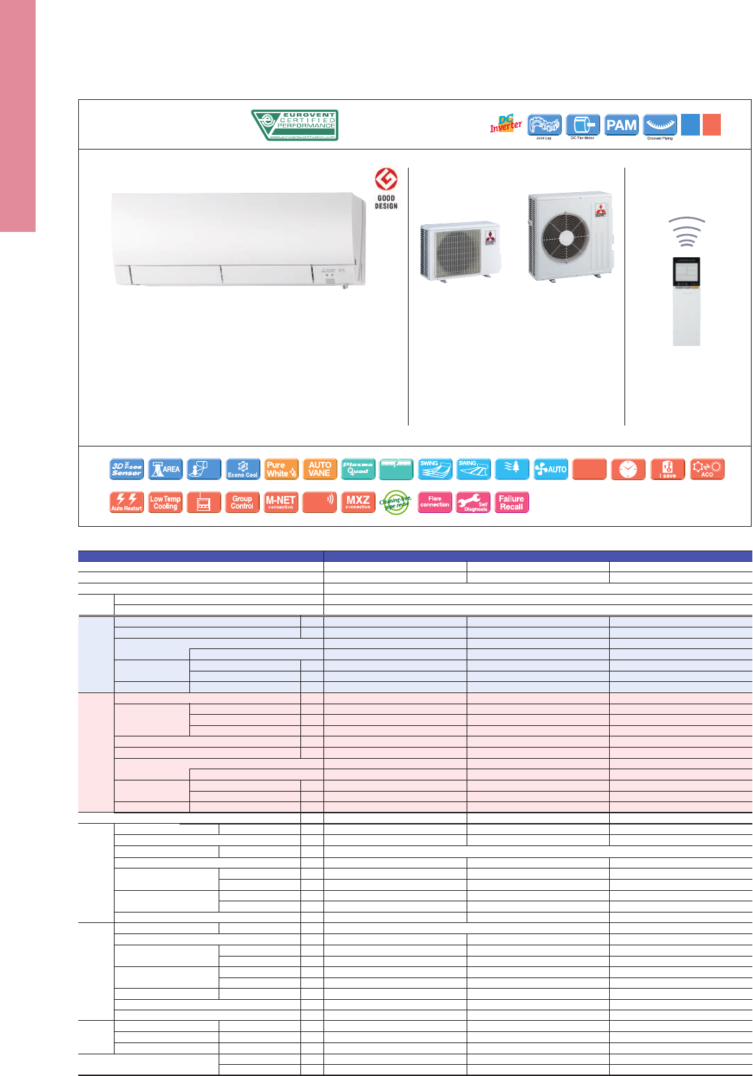
R410A
(
*
1)
Outdoor power supply
230 / Single / 50
Inverter Heat Pump
Operating Current (max)
Indoor
Unit
Outdoor
Unit
Ext.
Piping
Guaranteed Operating Range
[Outdoor]
Source
Outdoor (V/Phase/Hz)
Input
Operating Current (max)
Dimensions
Weight
Air Volume
(SLo-Lo-Mid-Hi-SHi
(
*
3)
(Dry/Wet))
Sound Level (SPL)
(SLo-Lo-Mid-Hi-SHi
(
*
3)
)
Sound Level (PWL)
Dimensions
Weight
Air Volume
Sound Level (SPL)
Sound Level (PWL)
Operating Current (max)
Breaker Size
Diameter
Max. Length
Max. Height
Rated
H × W × D
H × W × D
Cooling
Heating
Cooling
Cooling
Heating
Cooling
Heating
Cooling
Heating
Liquid / Gas
Out-In
Out-In
Cooling
Heating
kW
A
A
mm
kg
m
3
/min
dB(A)
dB(A)
m
3
/min
dB(A)
mm
kg
m
3
/min
m
3
/min
dB(A)
dB(A)
dB(A)
A
A
mm
m
m
o
C
o
C
MSZ-FH35VE(2) MSZ-FH50VE(2)MSZ-FH25VE(2)
MUZ-FH25VEHZ MUZ-FH35VEHZ
(*1) Refrigerant leakage contributes to climate change. Refrigerant with lower global warming potential (GWP) would contribute less to global warming than a refrigerant with higher GWP, if leaked to the atmosphere.
This appliance contains a refrigerant uid with a GWP equal to 1975. This means that if 1kg of this refrigerant uid would be leaked to the atmosphere, the impact on global warming would be 1975 times higher
than 1kg of CO2, over a period of 100 years. Never try to interfere with the refrigerant circuit yourself or disassemble the product yourself and always ask a professional.
(*2) Energy consumption based on standard test results. Actual energy consumption will depend on how the appliance is used and where it is located.
(*3) SHi: Super High
(*4) SEER, SCOP and other related description are based on COMMISSION DELEGATED REGULATION (EU) No.626/2011. The temperature conditions for calculating SCOP are based on “Average Season”.
(*5) Please see page 47 for heating (warmer season) specications.
Type
Indoor Unit
Outdoor Unit
Refrigerant
Power
Supply
MUZ-FH50VEHZ
2.5
96
9.1
A
+++
2.5
0.8 - 3.5
0.485
3.2
3.2
3.2
1.7
0.0
924
4.9
A
++
3.2
1.0 - 6.3
0.580
9.6
0.029
0.4
13.5
3.9 - 4.7 - 6.3 - 8.6 - 11.6 (10.5)
4.0 - 4.7 - 6.4 - 9.2 - 13.2
20 - 23 - 29 - 36 - 42
20 - 24 - 29 - 36 - 44
58
37
31.3
31.3
46
49
60
9.2
10
6.35 / 9.52
20
12
–10 ~ +46
–25 ~ +24
3.5
138
8.9
A
+++
3.5
0.8 - 4.0
0.820
4.0
4.0
4.0
2.6
0.0
1173
4.8
A
++
4.0
1.0 - 6.6
0.800
10.5
0.029
0.4
305 (+17) - 925 - 234
13.5
3.9 - 4.7 - 6.3 - 8.6 - 11.6 (10.5)
4.0 - 4.7 - 6.4 - 9.2 - 13.2
21 - 24 - 29 - 36 - 42
21 - 24 - 29 - 36 - 44
58
37
33.6
33.6
49
50
61
10.1
12
6.35 / 9.52
20
12
–10 ~ +46
–25 ~ +24
5.0
244
7.2
A
++
5.0
1.9 - 6.0
1.380
6.0
6.0
6.0
3.8
0.0
2006
4.2
A
+
6.0
1.7 - 8.7
1.480
14.0
0.031
0.4
13.5
6.4 - 7.4 - 8.6 - 10.1 - 12.4
5.7 - 7.2 - 9.0 - 11.2 - 14.6
27 - 31 - 35 - 39 - 44
25 - 29 - 34 - 39 - 46
60
880 - 840 - 330
55
48.8
51.3
51
54
64
13.6
16
6.35 / 12.7
30
15
–10 ~ +46
–25 ~ +24
550 - 800 - 285
(*1) Refrigerant leakage contributes to climate change. Refrigerant with lower global warming potential (GWP) would contribute less to global warming than a refrigerant with higher GWP, if leaked to the atmosphere.
This appliance contains a refrigerant uid with a GWP equal to 1975. This means that if 1kg of this refrigerant uid would be leaked to the atmosphere, the impact on global warming would be 1975 times higher
than 1kg of CO2, over a period of 100 years. Never try to interfere with the refrigerant circuit yourself or disassemble the product yourself and always ask a professional.
(*2) Energy consumption based on standard test results. Actual energy consumption will depend on how the appliance is used and where it is located.
(*3) SHi: Super High
(*4) SEER, SCOP and other related description are based on COMMISSION DELEGATED REGULATION (EU) No.626/2011. The temperature conditions for calculating SCOP are based on “Average Season”.
R410A
(
*
1)
Outdoor power supply
230 / Single / 50
Inverter Heat Pump
Cooling
Heating
(Average
Season)
Operating Current (max)
Indoor
Unit
Outdoor
Unit
Ext.
Piping
Guaranteed Operating Range
[Outdoor]
Source
Outdoor (V/Phase/Hz)
Design Load
Annual Electricity Consumption
(
*
2)
SEER
(
*
4)
Design Load
Declared Capacity
Back Up Heating Capacity
Annual Electricity Consumption
(
*
2)
SCOP
(
*
4)
Input
Operating Current (max)
Dimensions
Weight
Air Volume
(SLo-Lo-Mid-Hi-SHi
(
*
3)
(Dry/Wet))
Sound Level (SPL)
(SLo-Lo-Mid-Hi-SHi
(
*
3)
)
Sound Level (PWL)
Dimensions
Weight
Air Volume
Sound Level (SPL)
Sound Level (PWL)
Operating Current (max)
Breaker Size
Diameter
Max. Length
Max. Height
Energy Eciency Class
at reference design temperature
at bivalent temperature
at operation limit temperature
Energy Eciency Class
Rated
H × W × D
H × W × D
Cooling
Heating
Cooling
Cooling
Heating
Cooling
Heating
Cooling
Heating
Liquid / Gas
Out-In
Out-In
Cooling
Heating
kW
kWh/a
kW
kW
kW
kW
kW
kWh/a
kW
A
A
mm
kg
m
3
/min
dB(A)
dB(A)
m
3
/min
dB(A)
mm
kg
m
3
/min
m
3
/min
dB(A)
dB(A)
dB(A)
A
A
mm
m
m
o
C
o
C
MFZ-KJ35VE(2) MFZ-KJ50VE(2)MFZ-KJ25VE(2)
MUFZ-KJ25VEHZ MUFZ-KJ35VEHZ
Type
Indoor Unit
Outdoor Unit
Refrigerant
Power
Supply
MUFZ-KJ50VEHZ
2.5
102
8.5
A
+++
2.5
0.5 - 3.4
0.540
3.5
3.5
3.5
1.6
0.0
1104
4.4
A
+
3.4
1.2 - 5.1
0.770
4.42
0.016
0.17
15
3.9 - 4.9 - 5.9 - 7.1 - 8.2
3.9 - 5.1 - 6.2 - 7.7 - 9.7
20 - 25 - 30 - 35 - 39
19 - 25 - 30 - 35 - 41
49
37
31.3
33.6
46
51
59
9.2
10
6.35 / 9.52
20
12
–10 ~ +46
–25 ~ +24
3.5
150
8.1
A
++
3.5
0.5 - 3.7
0.940
3.6
3.6
3.6
2.3
0.0
1158
4.3
A
+
4.3
1.2 - 5.8
1.100
3.91
0.016
0.17
600 - 750 - 215
15
3.9 - 4.9 - 5.9 - 7.1 - 8.2
3.9 - 5.1 - 6.2 - 7.7 - 9.7
20 - 25 - 30 - 35 - 39
19 - 25 - 30 - 35 - 41
50
37
31.3
33.6
47
51
60
10
12
6.35 / 9.52
20
12
–10 ~ +46
–25 ~ +24
5.0
266
6.5
A
++
5.0
1.6 - 5.7
1.410
4.5
4.5
4.5
3.3
0.0
1467
4.2
A
+
6.0
2.2 - 8.4
1.610
3.73
0.038
0.34
15
5.6 - 6.7 - 8.0 - 9.3 - 10.6
6.0 - 7.4 - 9.4 - 11.6 - 14.0
27 - 31 - 35 - 39 - 44
29 - 35 - 40 - 45 - 50
56
880 - 840 - 330
55
45.8
45.8
49
51
63
13.6
16
6.35 / 12.7
30
15
–10 ~ +46
–25 ~ +24
550 - 800 - 285
Capacity
Total Input
Rated
Min - Max
Rated
kW
kW
kW
Capacity
Total Input
Rated
Min - Max
Rated
kW
kW
kW
Cooling
Heating
(Average
Season)
(
*
5)
Design Load
Annual Electricity Consumption
(
*
2)
SEER
(
*
4)
Design Load
Declared Capacity
Back Up Heating Capacity
Annual Electricity Consumption
(
*
2)
SCOP
(
*
4)
Energy Eciency Class
at reference design temperature
at bivalent temperature
at operation limit temperature
Energy Eciency Class
kW
kWh/a
kW
kW
kW
kW
kW
kWh/a
Capacity
Total Input
Rated
Min - Max
Rated
kW
kW
kW
Capacity
Total Input
Rated
Min - Max
Rated
kW
kW
kW
MUZ-FH25/35VEHZ MUZ-FH50VEHZ
Indoor Unit Outdoor Unit
MSZ-FH25/35/50VE2
MSZ-FH VEHZ SERIES
OptionalOptional
Optional Optional
HUMAN
Weekly
Timer
Natural Flow
SEER
A
+++
SCOP
A
++
25-35 25-35
Wi-Fi
Interface
Wi-Fi
Interface
Optional
Electrostatic
Anti-allergy
Remote Controller
Please fill out the requested information
Please fill out the requested information
Indoor Unit Outdoor Unit
Remote Controller
MFZ-KJ SERIES
MUFZ-KJ25/35VEHZ
MUFZ-KJ50VEHZ
Optional
Optional
OptionalOptional
Nano
Platinum
SCOP
A
+
SEER
A
+++
25
Please fill out the requested information
Please fill out the requested information
MFZ-KJ25/35/50VE2
109
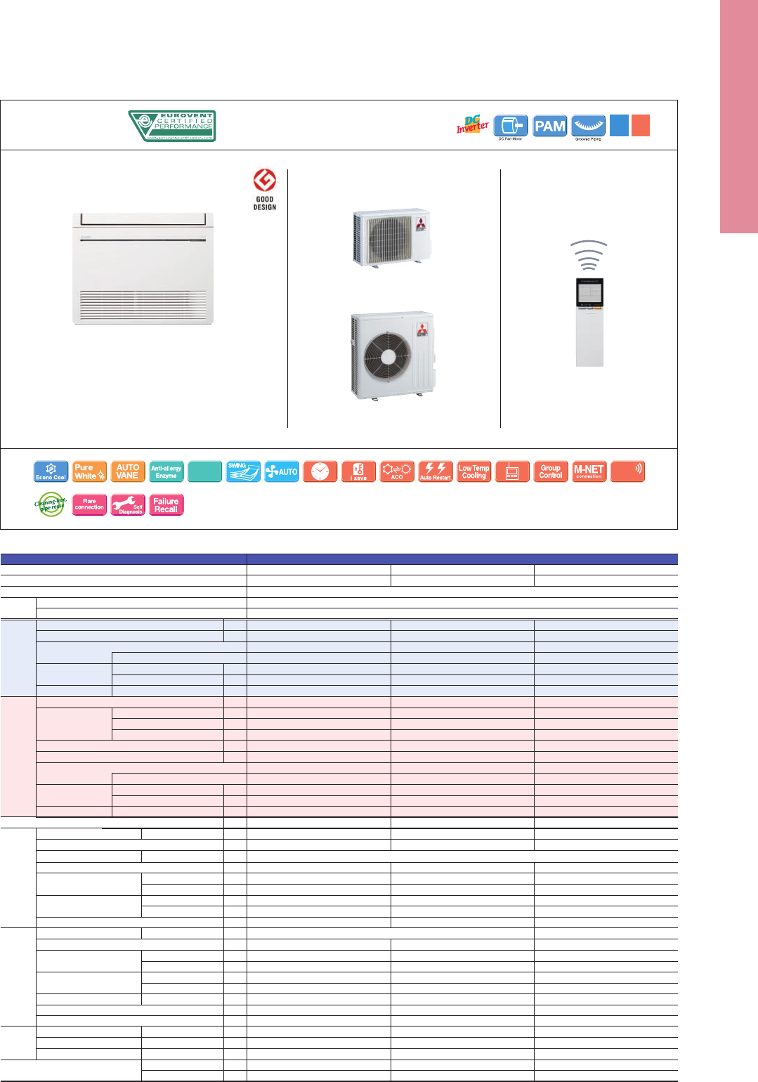
R410A
(
*
1)
Outdoor power supply
230 / Single / 50
Inverter Heat Pump
Operating Current (max)
Indoor
Unit
Outdoor
Unit
Ext.
Piping
Guaranteed Operating Range
[Outdoor]
Source
Outdoor (V/Phase/Hz)
Input
Operating Current (max)
Dimensions
Weight
Air Volume
(SLo-Lo-Mid-Hi-SHi
(
*
3)
(Dry/Wet))
Sound Level (SPL)
(SLo-Lo-Mid-Hi-SHi
(
*
3)
)
Sound Level (PWL)
Dimensions
Weight
Air Volume
Sound Level (SPL)
Sound Level (PWL)
Operating Current (max)
Breaker Size
Diameter
Max. Length
Max. Height
Rated
H × W × D
H × W × D
Cooling
Heating
Cooling
Cooling
Heating
Cooling
Heating
Cooling
Heating
Liquid / Gas
Out-In
Out-In
Cooling
Heating
kW
A
A
mm
kg
m
3
/min
dB(A)
dB(A)
m
3
/min
dB(A)
mm
kg
m
3
/min
m
3
/min
dB(A)
dB(A)
dB(A)
A
A
mm
m
m
o
C
o
C
MSZ-FH35VE(2) MSZ-FH50VE(2)MSZ-FH25VE(2)
MUZ-FH25VEHZ MUZ-FH35VEHZ
(*1) Refrigerant leakage contributes to climate change. Refrigerant with lower global warming potential (GWP) would contribute less to global warming than a refrigerant with higher GWP, if leaked to the atmosphere.
This appliance contains a refrigerant uid with a GWP equal to 1975. This means that if 1kg of this refrigerant uid would be leaked to the atmosphere, the impact on global warming would be 1975 times higher
than 1kg of CO2, over a period of 100 years. Never try to interfere with the refrigerant circuit yourself or disassemble the product yourself and always ask a professional.
(*2) Energy consumption based on standard test results. Actual energy consumption will depend on how the appliance is used and where it is located.
(*3) SHi: Super High
(*4) SEER, SCOP and other related description are based on COMMISSION DELEGATED REGULATION (EU) No.626/2011. The temperature conditions for calculating SCOP are based on “Average Season”.
(*5) Please see page 47 for heating (warmer season) specications.
Type
Indoor Unit
Outdoor Unit
Refrigerant
Power
Supply
MUZ-FH50VEHZ
2.5
96
9.1
A
+++
2.5
0.8 - 3.5
0.485
3.2
3.2
3.2
1.7
0.0
924
4.9
A
++
3.2
1.0 - 6.3
0.580
9.6
0.029
0.4
13.5
3.9 - 4.7 - 6.3 - 8.6 - 11.6 (10.5)
4.0 - 4.7 - 6.4 - 9.2 - 13.2
20 - 23 - 29 - 36 - 42
20 - 24 - 29 - 36 - 44
58
37
31.3
31.3
46
49
60
9.2
10
6.35 / 9.52
20
12
–10 ~ +46
–25 ~ +24
3.5
138
8.9
A
+++
3.5
0.8 - 4.0
0.820
4.0
4.0
4.0
2.6
0.0
1173
4.8
A
++
4.0
1.0 - 6.6
0.800
10.5
0.029
0.4
305 (+17) - 925 - 234
13.5
3.9 - 4.7 - 6.3 - 8.6 - 11.6 (10.5)
4.0 - 4.7 - 6.4 - 9.2 - 13.2
21 - 24 - 29 - 36 - 42
21 - 24 - 29 - 36 - 44
58
37
33.6
33.6
49
50
61
10.1
12
6.35 / 9.52
20
12
–10 ~ +46
–25 ~ +24
5.0
244
7.2
A
++
5.0
1.9 - 6.0
1.380
6.0
6.0
6.0
3.
8
0.0
2006
4.2
A
+
6.0
1.7 - 8.7
1.480
14.0
0.031
0.4
13.5
6.4 - 7.4 - 8.6 - 10.1 - 12.4
5.7 - 7.2 - 9.0 - 11.2 - 14.6
27 - 31 - 35 - 39 - 44
25 - 29 - 34 - 39 - 46
60
880 - 840 - 330
55
48.8
51.3
51
54
64
13.6
16
6.35 / 12.7
30
15
–10 ~ +46
–25 ~ +24
550 - 800 - 285
(*1) Refrigerant leakage contributes to climate change. Refrigerant with lower global warming potential (GWP) would contribute less to global warming than a refrigerant with higher GWP, if leaked to the atmosphere.
This appliance contains a refrigerant uid with a GWP equal to 1975. This means that if 1kg of this refrigerant uid would be leaked to the atmosphere, the impact on global warming would be 1975 times higher
than 1kg of CO2, over a period of 100 years. Never try to interfere with the refrigerant circuit yourself or disassemble the product yourself and always ask a professional.
(*2) Energy consumption based on standard test results. Actual energy consumption will depend on how the appliance is used and where it is located.
(*3) SHi: Super High
(*4) SEER, SCOP and other related description are based on COMMISSION DELEGATED REGULATION (EU) No.626/2011. The temperature conditions for calculating SCOP are based on “Average Season”.
R410A
(
*
1)
Outdoor power supply
230 / Single / 50
Inverter Heat Pump
Cooling
Heating
(Average
Season)
Operating Current (max)
Indoor
Unit
Outdoor
Unit
Ext.
Piping
Guaranteed Operating Range
[Outdoor]
Source
Outdoor (V/Phase/Hz)
Design Load
Annual Electricity Consumption
(
*
2)
SEER
(
*
4)
Design Load
Declared Capacity
Back Up Heating Capacity
Annual Electricity Consumption
(
*
2)
SCOP
(
*
4)
Input
Operating Current (max)
Dimensions
Weight
Air Volume
(SLo-Lo-Mid-Hi-SHi
(
*
3)
(Dry/Wet))
Sound Level (SPL)
(SLo-Lo-Mid-Hi-SHi
(
*
3)
)
Sound Level (PWL)
Dimensions
Weight
Air Volume
Sound Level (SPL)
Sound Level (PWL)
Operating Current (max)
Breaker Size
Diameter
Max. Length
Max. Height
Energy Eciency Class
at reference design temperature
at bivalent temperature
at operation limit temperature
Energy Eciency Class
Rated
H × W × D
H × W × D
Cooling
Heating
Cooling
Cooling
Heating
Cooling
Heating
Cooling
Heating
Liquid / Gas
Out-In
Out-In
Cooling
Heating
kW
kWh/a
kW
kW
kW
kW
kW
kWh/a
kW
A
A
mm
kg
m
3
/min
dB(A)
dB(A)
m
3
/min
dB(A)
mm
kg
m
3
/min
m
3
/min
dB(A)
dB(A)
dB(A)
A
A
mm
m
m
o
C
o
C
MFZ-KJ35VE(2) MFZ-KJ50VE(2)MFZ-KJ25VE(2)
MUFZ-KJ25VEHZ MUFZ-KJ35VEHZ
Type
Indoor Unit
Outdoor Unit
Refrigerant
Power
Supply
MUFZ-KJ50VEHZ
2.5
102
8.5
A
+++
2.5
0.5 - 3.4
0.540
3.5
3.5
3.5
1.6
0.0
1104
4.4
A
+
3.4
1.2 - 5.1
0.770
4.42
0.016
0.17
15
3.9 - 4.9 - 5.9 - 7.1 - 8.2
3.9 - 5.1 - 6.2 - 7.7 - 9.7
20 - 25 - 30 - 35 - 39
19 - 25 - 30 - 35 - 41
49
37
31.3
33.6
46
51
59
9.2
10
6.35 / 9.52
20
12
–10 ~ +46
–25 ~ +24
3.5
150
8.1
A
++
3.5
0.5 - 3.7
0.940
3.6
3.6
3.6
2.3
0.0
1158
4.3
A
+
4.3
1.2 - 5.8
1.100
3.91
0.016
0.17
600 - 750 - 215
15
3.9 - 4.9 - 5.9 - 7.1 - 8.2
3.9 - 5.1 - 6.2 - 7.7 - 9.7
20 - 25 - 30 - 35 - 39
19 - 25 - 30 - 35 - 41
50
37
31.3
33.6
47
51
60
10
12
6.35 / 9.52
20
12
–10 ~ +46
–25 ~ +24
5.0
266
6.5
A
++
5.0
1.6 - 5.7
1.410
4.5
4.5
4.5
3.3
0.0
1467
4.2
A
+
6.0
2.2 - 8.4
1.610
3.73
0.038
0.34
15
5.6 - 6.7 - 8.0 - 9.3 - 10.6
6.0 - 7.4 - 9.4 - 11.6 - 14.0
27 - 31 - 35 - 39 - 44
29 - 35 - 40 - 45 - 50
56
880 - 840 - 330
55
45.8
45.8
49
51
63
13.6
16
6.35 / 12.7
30
15
–10 ~ +46
–25 ~ +24
550 - 800 - 285
Capacity
Total Input
Rated
Min - Max
Rated
kW
kW
kW
Capacity
Total Input
Rated
Min - Max
Rated
kW
kW
kW
Cooling
Heating
(Average
Season)
(
*
5)
Design Load
Annual Electricity Consumption
(
*
2)
SEER
(
*
4)
Design Load
Declared Capacity
Back Up Heating Capacity
Annual Electricity Consumption
(
*
2)
SCOP
(
*
4)
Energy Eciency Class
at reference design temperature
at bivalent temperature
at operation limit temperature
Energy Eciency Class
kW
kWh/a
kW
kW
kW
kW
kW
kWh/a
Capacity
Total Input
Rated
Min - Max
Rated
kW
kW
kW
Capacity
Total Input
Rated
Min - Max
Rated
kW
kW
kW
MUZ-FH25/35VEHZ MUZ-FH50VEHZ
Indoor Unit Outdoor Unit
MSZ-FH25/35/50VE2
MSZ-FH VEHZ SERIES
OptionalOptional
Optional Optional
HUMAN
Weekly
Timer
Natural Flow
SEER
A
+++
SCOP
A
++
25-35 25-35
Wi-Fi
Interface
Wi-Fi
Interface
Optional
Electrostatic
Anti-allergy
Remote Controller
Please fill out the requested information
Please fill out the requested information
Indoor Unit Outdoor Unit
Remote Controller
MFZ-KJ SERIES
MUFZ-KJ25/35VEHZ
MUFZ-KJ50VEHZ
Optional
Optional
OptionalOptional
Nano
Platinum
SCOP
A
+
SEER
A
+++
25
Please fill out the requested information
Please fill out the requested information
MFZ-KJ25/35/50VE2
110
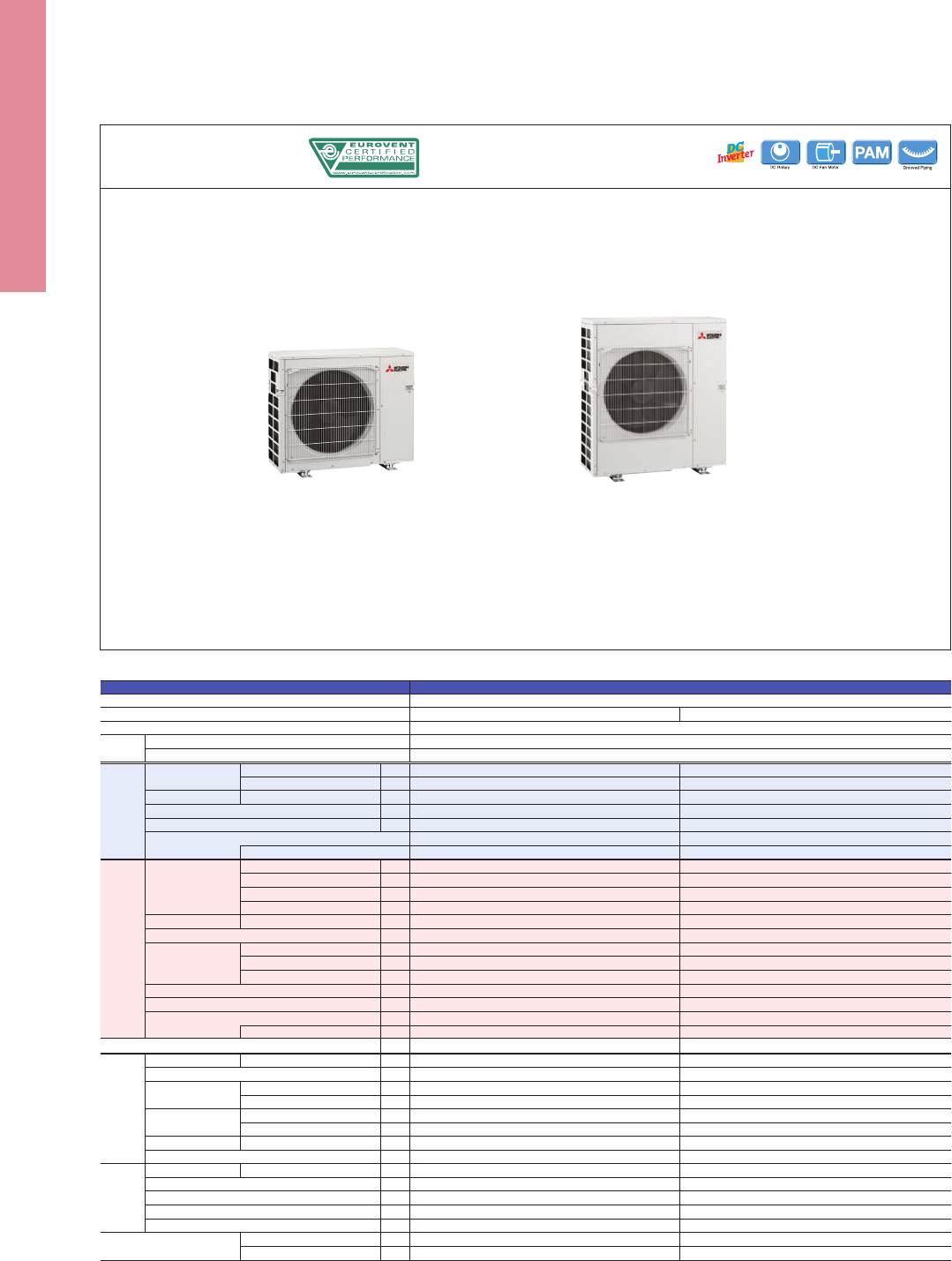
Outdoor Unit
MXZ-VAHZ SERIES
Please fill out the requested information
Please fill out the requested information
R410A*
1
Outdoor power supply
230 / Single / 50
Inverter Heat Pump
Cooling
Heating
(Average
Season)
Max. Operating Current (Indoor+Outdoor)
Outdoor
Unit
Ext.
Piping
Guaranteed Operating Range
[Outdoor]
Source
Outdoor (V/Phase/Hz)
Capacity
Total Input
Design Load
Annual Electricity Consumption*
2
SEER*
4
Capacity
Total Input
Design Load
Declared Capacity
Back Up Heating Capacity
Annual Electricity Consumption*
2
SCOP
Dimensions
Weight
Air Volume
Sound Level (SPL)
Sound Level (PWL)
Breaker Size
Diameter
Total Piping Length (max)
Each Indoor Unit Piping Length (max)
Max. Height
Chargeless Length
Rated
Min - Max
Rated
Energy Efficiency Class*
4
Rated (7°C)
Rated (–7°C)
Rated (–15°C)
Min - Max
Rated
at reference design temperature
at bivalent temperature
at operation limit temperature
Energy Efficiency Class*
4
H × W × D
Cooling
Heating
Cooling
Cooling
Heating
Liquid / Gas
Cooling
Heating
kW
kW
kW
kW
kWh/a
kW
kW
kW
kW
kW
kW
kW
kW
kW
kW
kWh/a
A
mm
kg
m
3
/min
m
3
/min
dB(A)
dB(A)
dB(A)
A
mm
m
m
m
m
o
C
o
C
Please refer to*
4
*
5
MXZ-2E53VAHZ MXZ-4E83VAHZ
*1 Refrigerant leakage contributes to climate change. Refrigerant with lower global warming potential (GWP) would contribute less to global warming than a refrigerant with higher GWP, if leaked to the atmosphere.
This appliance contains a refrigerant fluid with a GWP equal to 1975. This means that if 1 kg of this refrigerant fluid would be leaked to the atmosphere, the impact on global warming would be 1975 times higher
than 1 kg of CO2 , over a period of 100 years. Never try to interfere with the refrigerant circuit yourself or disassemble the product yourself and always ask a professional.
*2 Energy consumption based on standard test results.
Actual energy consumption will depend on how the appliance is used and where it is located.
*3 If the outdoor unit is installed higher than the indoor unit, max. height is reduced to 10m.
*4 EER/COP, EEL rank, SEER/SCOP values and energy efficiency class are measured
when connected to the indoor units listed below.
MXZ-2E53VAHZ MSZ-EF18VE + MSZ-EF35VE
MXZ-4E83VAHZ MSZ-EF18VE + MSZ-EF18VE + MSZ-EF22VE + MSZ-EF25VE
*5 Indoor unit compatibility table is shown on page 93.
Type
Indoor Unit
Outdoor Unit
Refrigerant
Power
Supply
5.3
1.1 - 6.0
1.29
5.3
282
6.5
A
++
6.4
6.4
6.4
1.0 - 7.0
1.36
6.4
6.4
6.4
2.4
0.0
2165
4.1
A
+
15.6
796 × 950 × 330
61
47.0
47.0
45
47
55
16
6.35 × 2 / 9.52 × 2
30
20
15 (10) *
3
20
–10 ~ +46
–25 ~ +24
8.3
3.5 - 9.2
2.25
8.3
447
6.5
A
++
9.0
9.0
9.0
3.5 - 11.6
1.90
10.1
9.0
9.0
2.5
1.1
3446
4.1
A
+
28.0
1048 × 950 × 330
87
63.0
77.0
53
57
66
30
6.35× 4 / 12.7 × 1+9.52× 3
70
25
15 (10) *
3
25
–10 ~ +46
–25 ~ +24
MXZ-2E53VAHZ MXZ-4E83VAHZ
4E
111
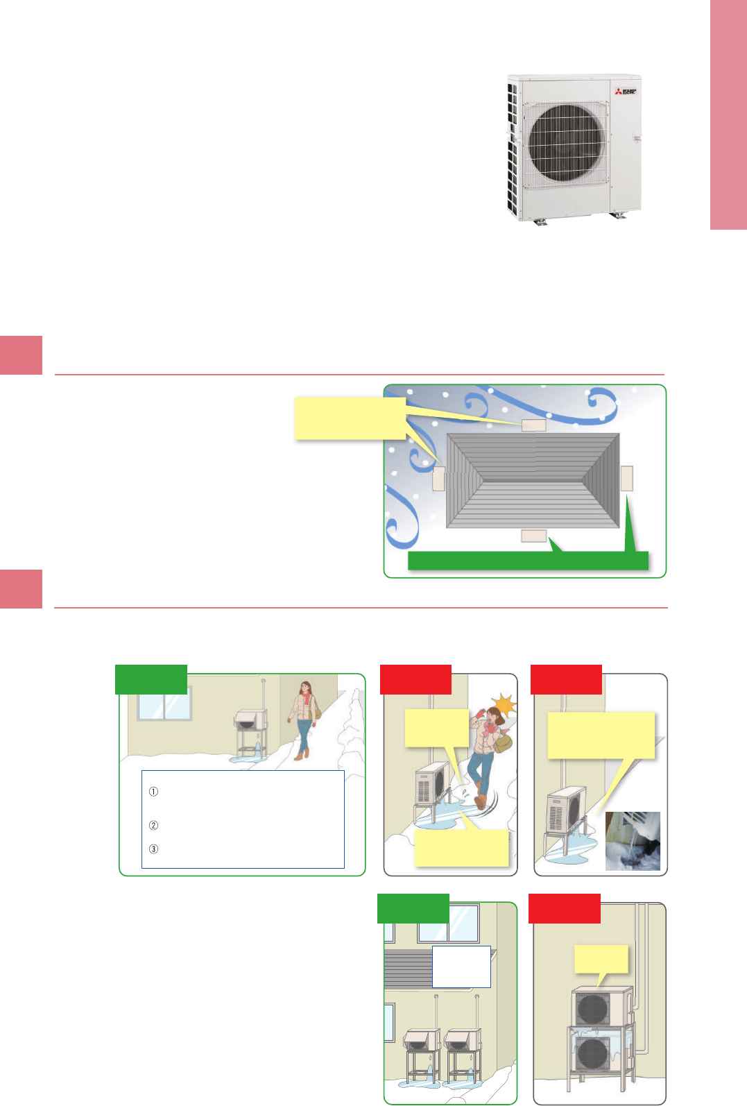
To ensure full capacity in cold and snowy regions…
Installation Location
Be aware of the prevailing wind direction in winter and install
the outdoor unit where it is as sheltered as possible.
Case 2:
Multiple units are installed
Do not install units on top of one another as it may
cause frozen drainage water on the bottom unit.
Case 1:
Unit is installed close to passage (walkway)
Do not install the unit close to passage as drainage water from the unit may freeze and cause a slipping hazard.
Less influence of wind and unit runs at full capacity
3 Important Points to Remember
When Installing the Outdoor Unit
1
Place units
side by side.
Note!
Correct
installation
Bottom unit
may freeze.
Wrong
installation
Drainage water
splashes on
pedestrians.
Frozen drainage water
may cause a slipping
hazard.
Unit may freeze and
become damaged because
water will not be drained
from the drain hole.
Wrong
installation
Wrong
installation
Install at a sufficient height from the ground
to prevent problems caused by frozen
drainage water.
Install in a location where frozen drainage
water will not be a hazard.
Install in an upright position to allow proper
drainage from the drainage outlet.
Correct
installation
Point!
Wind and snow can significantly reduce capacity.
Be sure to check the infomation below and install the outdoor unit correctly.
✽
RAC/PAC (inc. Air to Water) /MXZ
Units are easily affected by
wind and unit may not be
able to run at full capacity
Measures for Drainage of Water
2
112
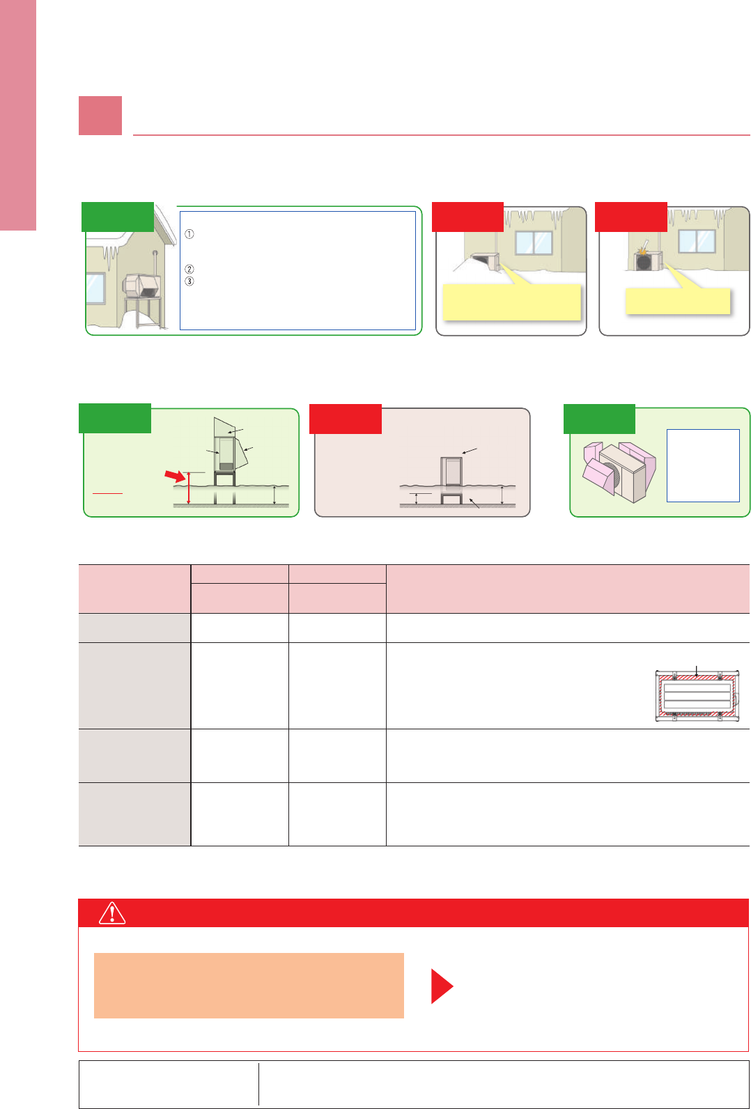
Measures for Snow
About disposal of drainage water
When the unit is installed in cold or snowy regions :
Arrangement for
snow protection hood
[RAC /PAC / MXZ]
Separately sold parts are available for some models.
Please consult Mitsubishi Electric or one of its dealers/resellers at the time of purchase for details.
✽
In the case that fitting a drain socket is absolutely necessary, steps must be taken so that the drainage water does not freeze.
For more information, please consult Mitsubishi Electric or one of its dealers/resellers.
Necessity of accessories
(drain socket & centralised drain pan, stand, snow protection hood, base heater)
Unit is installed on the ground
Drainage water may freeze in
the drain socket/hose and prevent
the fan from rotating.
Do not attach a drain socket
packaged as an accessory
to the unit.
To avoid the adverse effects of snow and frozen drainage water, install the unit on a stand to ensure a sufficient height from the ground.
Use a stand to add sufficient height to protect the unit’s heat exchanger from snow and prevent
icicles forming during defrost operation.
Install at a position/height to prevent the unit being
buried in snow
*
1
and the adverse effects of frozen
drainage water.
*
2
Install so as to avoid the effects of snow or snowdrift.
Install so as to avoid the damage from falling snow or icicles.
*
1
Install at a height above the highest snowfall depth.
*
2
Even for correct installations, dripping drainage water may
form an icicle which needs to be cleared away regularly to
prevent a blocked drainage outlet.
Point!
Unit may become buried in snow
due to heavy snowfall, snow sliding
off the roof or snowdrift.
Unit may be damaged
due to snowfall or icicles.
Correct
installation
Snowy region
Snow
protection
hood
Needed
*When the installation
position is subject to
snowfall.
1. Prevents heat exchanger from being covered in snow.
2. Prevents snow accumulating inside the air duct.
[
RAC/PAC/MXZ
]
1. Install so as to prevent the unit being buried
in snow (at a height greater than the highest
snowfall depth). Be sure that the stand does
not obstruct drainage.
2. Install so as to prevent damage to the unit
due to frozen drainage water (icicles).
[
RAC /PAC/MXZ
]
Outdoor units equipped with a heater for cold regions are those with an“H”
in the model name. For the cold-climate zone, use of a unit with a heater is
strongly recommended. Even for the moderate-climate zone use of a unit with
a heater is recommended for regions subject to high humidity in winter.
Needed
—
—
Needed
Needed
Stand
Prevents freezing
Not used Not used
Drain socket,
Centralised drain pan
Base heater
Countermeasures
for snow
Cold region
Countermeasures
for freezing
Remarks
Wrong
installation
Wrong
installation
Without hood
Stand height h
Snowfall
height h0
Stand is too low.
Wi
t
h
out
h
oo
d
ig
ht
h
S
nowfall
h
e
i
g
h
t
h
0
Wrong
installation
Unit may become
covered in snow
if the stand height
is insufficient.
Air intake
snow hood
(side panel)
Air intake
snow hood
(rear)
Air exhaust
snow hood
h
h0
Correct
installation
Minimum height
(
h
)
should be higher
than the highest
snowfall depth
(
h0
)
+20cm
[
RAC/PAC/MXZ
]
Install snow protection hood
as necessary
Point!
Install the snow
protection hood
or other cover in
snowy regions.
Correct
installation
[
RAC/PAC / MXZ
]
CAUTION
3
<Correct>
Clearance to prevent
snow accumulating.
113

Measures for Snow
About disposal of drainage water
When the unit is installed in cold or snowy regions :
Arrangement for
snow protection hood
[RAC /PAC / MXZ]
Separately sold parts are available for some models.
Please consult Mitsubishi Electric or one of its dealers/resellers at the time of purchase for details.
✽
In the case that fitting a drain socket is absolutely necessary, steps must be taken so that the drainage water does not freeze.
For more information, please consult Mitsubishi Electric or one of its dealers/resellers.
Necessity of accessories
(drain socket & centralised drain pan, stand, snow protection hood, base heater)
Unit is installed on the ground
Drainage water may freeze in
the drain socket/hose and prevent
the fan from rotating.
Do not attach a drain socket
packaged as an accessory
to the unit.
To avoid the adverse effects of snow and frozen drainage water, install the unit on a stand to ensure a sufficient height from the ground.
Use a stand to add sufficient height to protect the unit’s heat exchanger from snow and prevent
icicles forming during defrost operation.
Install at a position/height to prevent the unit being
buried in snow
*
1
and the adverse effects of frozen
drainage water.
*
2
Install so as to avoid the effects of snow or snowdrift.
Install so as to avoid the damage from falling snow or icicles.
*
1
Install at a height above the highest snowfall depth.
*
2
Even for correct installations, dripping drainage water may
form an icicle which needs to be cleared away regularly to
prevent a blocked drainage outlet.
Point!
Unit may become buried in snow
due to heavy snowfall, snow sliding
off the roof or snowdrift.
Unit may be damaged
due to snowfall or icicles.
Correct
installation
Snowy region
Snow
protection
hood
Needed
*When the installation
position is subject to
snowfall.
1. Prevents heat exchanger from being covered in snow.
2. Prevents snow accumulating inside the air duct.
[
RAC/PAC/MXZ
]
1. Install so as to prevent the unit being buried
in snow (at a height greater than the highest
snowfall depth). Be sure that the stand does
not obstruct drainage.
2. Install so as to prevent damage to the unit
due to frozen drainage water (icicles).
[
RAC /PAC/MXZ
]
Outdoor units equipped with a heater for cold regions are those with an“H”
in the model name. For the cold-climate zone, use of a unit with a heater is
strongly recommended. Even for the moderate-climate zone use of a unit with
a heater is recommended for regions subject to high humidity in winter.
Needed
—
—
Needed
Needed
Stand
Prevents freezing
Not used Not used
Drain socket,
Centralised drain pan
Base heater
Countermeasures
for snow
Cold region
Countermeasures
for freezing
Remarks
Wrong
installation
Wrong
installation
Without hood
Stand height h
Snowfall
height h0
Stand is too low.
Wi
t
h
out
h
oo
d
ig
ht
h
S
nowfall
h
e
i
g
h
t
h
0
Wrong
installation
Unit may become
covered in snow
if the stand height
is insufficient.
Air intake
snow hood
(side panel)
Air intake
snow hood
(rear)
Air exhaust
snow hood
h
h0
Correct
installation
Minimum height
(
h
)
should be higher
than the highest
snowfall depth
(
h0
)
+20cm
[
RAC/PAC/MXZ
]
Install snow protection hood
as necessary
Point!
Install the snow
protection hood
or other cover in
snowy regions.
Correct
installation
[
RAC/PAC / MXZ
]
CAUTION
3
<Correct>
Clearance to prevent
snow accumulating.
114
115
Relay
Major Optional Parts
Deodourising Filter
Captures small foul-smelling substances in
the air.
Quick-clean Kit
Cleaning tool to remove dust on the filter, fan
and heat exchanger. This tool can be easily
connected to a household vacuum cleaner for
quick, convenient cleaning of the units.
Control Holder
Holder for storing the remote controller.
Air-cleaning Filter
Removes fine dust particles from the air by
means of static electricity.
Drain Pump
Pumps drain water to a point higher than that
where the unit is installed.
Remote Sensor
Sensor to detect the room temperature at
remote positions.
Centralised Drain Pan
Catches drain water generated by the outdoor
unit.
Anti-allergen Enzyme Filter
Captures the bacteria, pollen and other aller-
gens in the air and neutralises them with the
enzyme in the filter.
Decorative Cover
To be attached to the upper section of ceiling-
suspended models for professional kitchen
use. Helps prevent dust accumulation.
Remote On/Off Adapter
Connector for receiving signals from the local
system to control the on/off function.
M-NET Converter
Used to connect P Series A-control models to
M-NET controllers.
Catechin Air Filter
Contains catechin, which has antiviral and
antibacterial characteristics.
MA & Contact Terminal Interface
Interface for connecting with the PAR-32MAA
remote controller and PAC-YT52CRA, and to
relay operation signals.
Remote Operation Adapter
Adapter to display the operation status and
control on/off function from a distance.
Control/Service Tool
Monitoring tool to display operation and self-
diagnosis data.
Oil Mist Filter Element
Filter element (12 pieces) that blocks the oil
mist for ceiling-suspended models used in
professional kitchens.
System Control Interface
Interface to connect with M-NET controllers.
Connector Cable for Remote
Display
Connector used to display the operation status
and control on/off function from a distance.
Step Interface
Interface for adjusting the capacity of inverter-
equipped outdoor units. (For further details,
refer to pg. 130.)
Remote control
MELCloud allows you to take control of your Mitsubishi Electric systems
from anywhere in the world as long as you have internet access. So
forgetting to turn off your air conditioning or heating system when away on
holiday is no longer a problem.
Additional functions
MELCloud also provides some new functions, such as localised weather
information, frost protection, 7 day multi programmable timer and holiday
mode, with more features planned for the future.
User types
MELCloud has been designed for wide range of users from single users
with single air conditioning or heating systems in a single building, up to
larger user who may have multiple properties and multiple systems that they
wish to monitor and control.
Whichever type of user you are, MELCloud can provide you with required
control and access you need for modern living.
Remote operation can be achieved as long as you have a connected system and you
have an internet connection at the location of your equipment.
Local operation is also possible if you close to where the system that you wish to
control is, but simply to not wish to use the local controller and have your PC, Tablet
or Smartphone to hand. Please note this is not direct connection via router, local
cotnrol still requires internet connection to work.
MELCloud is a new Cloud based solution for
controlling your Mitsubishi Electric Air Conditioning
or Heating systems either locally or remotely by PC,
Tablet or Smartphone via the Internet.
High-efficiency Filter Element
Element for high-efficiency filter. Removes
fine dust particles from the air.
Distribution Pipe
Branch pipe for P Series simultaneous multi-
system use, or to connect two branch boxes
for MXZ-8B140V(Y)A/160V(Y)A systems.
Power Supply Terminal Kit
Terminal bed to change the power supply
from outdoor power supply to separate indoor/
outdoor power supplies.
Connector Cable
This product is an adaptor which inputs the
incoming signals from an open/close switch to
the air conditioner and outputs the on/off
signals from the air conditioner to the back-up
heater.
i-see Sensor Corner Panel for
PLA
Corner panel holding the i-see Sensor.
Simple Wired Remote Controller
Remote controller with liquid-crystal display,
and backlight function for operation in dark
location.
Wired Remote Controller
Advanced deluxe remote controller with full-
dot liquid-crystal display and backlight.
Equipped with convenient functions like night-
setback.
Joint Pipe
Part for connecting refrigerant pipes of differ-
ent diametres.
Shuttle Plate
Plate for blocking an air outlet of the 4-way
cassette (PLA) indoor unit.
Remote Controller Terminal Block
Kit for PKA
The terminal block is used as a relay to wire
an indoor unit and to two remote controllers or
to wire a remote controller and multiple indoor
units in order to perform group control.
Liquid Refrigerant Dryer
Removes water and minute particles from
refrigerant pipes.
Multi-functional Casement
Casement for fresh-air intake and attaching
the high-efficiency filter element (optional).
Wireless Remote Controller Signal
Sender
Handheld unit for sending operation signals to
the indoor unit.
Branch Box Outer Cover
Casement for branch boxes.
Fresh-air Intake Duct Flange
Flange attachment for adding a duct to take in
fresh air from outside.
Air Discharge Guide
Changes the direction of air being exhausted
from the outdoor unit.
Part Name escription
Air Protection Guide
Protects the outdoor unit from the wind.
Drain Socket
A set of caps to cover unnecessary holes at
the bottom of the outdoor unit, and a socket to
guide drain water to the local drain pipe.
Space Panel
ecorative cover for the installation when the
ceiling height is low.
Wireless Remote Controller Kit
(Sender & Receiver)
Remote controller handheld unit (signal sender)
and receiver (signal receiver) for ceiling-
suspended units.
Anti-allergen enzyme filter
Remote on/off adapter
oint pipe
Centralised drain pan
Part Name escription
Part Name escriptionPart Name escription
for wall-mounted units
for ceiling-suspended units
P Series with 2 indoor units
nsite pipe
Insulator
Base
(local construction)
Case interior
Air-cleaning filter
Filter frame
Filter element
uick-clean kit
Indoor unit
MA contact
terminal interface
Handheld unit
ecorative cover
rain pump
ecorative
cover
il mist filter
Shuttle Plate
Space Panel
Panel
Signal receiver
Signal sender
Wireless Remote Controller Signal
Receiver
Receives operation signals from the wireless
remote controller handheld unit.
System control
interface
Control holder
Remote sensor
Remote operation adapter
Connector cable for remote display
Branch box outer cover
Control/service tool
M-NET
Converter
utdoor uni t
eodourising filter
Complete view
Cap
Socket
Catechin air filter
Example of installation in wall-mounted unit
utdoor unit
utdoor unit
Indoor unit
Indoor unit
Indoor unit
Switch
WiFi interface
Smartphone
Wi-Fi Interface
( )
MELCloud
21°C
Wi-Fi Interface
Interface enabling users to control air condi-
tioners and check operating status via
devices such as personal computers, tablets
and smartphones.
For 4-way cassette units (PLA)
For 4-way cassette units (PLA)
Installed in case
i-see Sensor
corner panel
3D i-see Sensor Corner Panel for
SLZ
Corner panel holding the 3 i-see Sensor.
High-efficiency
filter element
Plug
(for directing
airflow)
Indoor unit body
Multi-functional
casement
istribution pipe
Signal receiver
i-see Sensor
corner panel
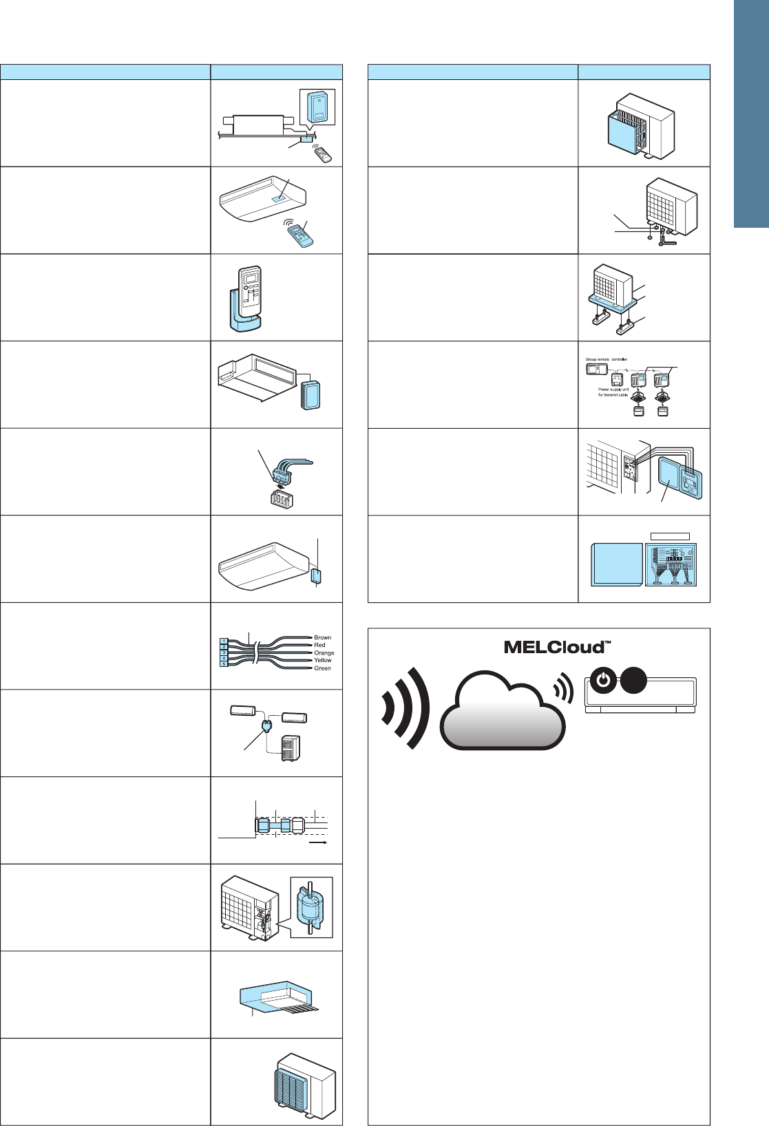
116
Relay
Major Optional Parts
Deodourising Filter
Captures small foul-smelling substances in
the air.
Quick-clean Kit
Cleaning tool to remove dust on the filter, fan
and heat exchanger. This tool can be easily
connected to a household vacuum cleaner for
quick, convenient cleaning of the units.
Control Holder
Holder for storing the remote controller.
Air-cleaning Filter
Removes fine dust particles from the air by
means of static electricity.
Drain Pump
Pumps drain water to a point higher than that
where the unit is installed.
Remote Sensor
Sensor to detect the room temperature at
remote positions.
Centralised Drain Pan
Catches drain water generated by the outdoor
unit.
Anti-allergen Enzyme Filter
Captures the bacteria, pollen and other aller-
gens in the air and neutralises them with the
enzyme in the filter.
Decorative Cover
To be attached to the upper section of ceiling-
suspended models for professional kitchen
use. Helps prevent dust accumulation.
Remote On/Off Adapter
Connector for receiving signals from the local
system to control the on/off function.
M-NET Converter
Used to connect P Series A-control models to
M-NET controllers.
Catechin Air Filter
Contains catechin, which has antiviral and
antibacterial characteristics.
MA & Contact Terminal Interface
Interface for connecting with the PAR-32MAA
remote controller and PAC-YT52CRA, and to
relay operation signals.
Remote Operation Adapter
Adapter to display the operation status and
control on/off function from a distance.
Control/Service Tool
Monitoring tool to display operation and self-
diagnosis data.
Oil Mist Filter Element
Filter element (12 pieces) that blocks the oil
mist for ceiling-suspended models used in
professional kitchens.
System Control Interface
Interface to connect with M-NET controllers.
Connector Cable for Remote
Display
Connector used to display the operation status
and control on/off function from a distance.
Step Interface
Interface for adjusting the capacity of inverter-
equipped outdoor units. (For further details,
refer to pg. 130.)
Remote control
MELCloud allows you to take control of your Mitsubishi Electric systems
from anywhere in the world as long as you have internet access. So
forgetting to turn off your air conditioning or heating system when away on
holiday is no longer a problem.
Additional functions
MELCloud also provides some new functions, such as localised weather
information, frost protection, 7 day multi programmable timer and holiday
mode, with more features planned for the future.
User types
MELCloud has been designed for wide range of users from single users
with single air conditioning or heating systems in a single building, up to
larger user who may have multiple properties and multiple systems that they
wish to monitor and control.
Whichever type of user you are, MELCloud can provide you with required
control and access you need for modern living.
Remote operation can be achieved as long as you have a connected system and you
have an internet connection at the location of your equipment.
Local operation is also possible if you close to where the system that you wish to
control is, but simply to not wish to use the local controller and have your PC, Tablet
or Smartphone to hand. Please note this is not direct connection via router, local
cotnrol still requires internet connection to work.
MELCloud is a new Cloud based solution for
controlling your Mitsubishi Electric Air Conditioning
or Heating systems either locally or remotely by PC,
Tablet or Smartphone via the Internet.
High-efficiency Filter Element
Element for high-efficiency filter. Removes
fine dust particles from the air.
Distribution Pipe
Branch pipe for P Series simultaneous multi-
system use, or to connect two branch boxes
for MXZ-8B140V(Y)A/160V(Y)A systems.
Power Supply Terminal Kit
Terminal bed to change the power supply
from outdoor power supply to separate indoor/
outdoor power supplies.
Connector Cable
This product is an adaptor which inputs the
incoming signals from an open/close switch to
the air conditioner and outputs the on/off
signals from the air conditioner to the back-up
heater.
i-see Sensor Corner Panel for
PLA
Corner panel holding the i-see Sensor.
Simple Wired Remote Controller
Remote controller with liquid-crystal display,
and backlight function for operation in dark
location.
Wired Remote Controller
Advanced deluxe remote controller with full-
dot liquid-crystal display and backlight.
Equipped with convenient functions like night-
setback.
Joint Pipe
Part for connecting refrigerant pipes of differ-
ent diametres.
Shuttle Plate
Plate for blocking an air outlet of the 4-way
cassette (PLA) indoor unit.
Remote Controller Terminal Block
Kit for PKA
The terminal block is used as a relay to wire
an indoor unit and to two remote controllers or
to wire a remote controller and multiple indoor
units in order to perform group control.
Liquid Refrigerant Dryer
Removes water and minute particles from
refrigerant pipes.
Multi-functional Casement
Casement for fresh-air intake and attaching
the high-efficiency filter element (optional).
Wireless Remote Controller Signal
Sender
Handheld unit for sending operation signals to
the indoor unit.
Branch Box Outer Cover
Casement for branch boxes.
Fresh-air Intake Duct Flange
Flange attachment for adding a duct to take in
fresh air from outside.
Air Discharge Guide
Changes the direction of air being exhausted
from the outdoor unit.
Part Name escription
Air Protection Guide
Protects the outdoor unit from the wind.
Drain Socket
A set of caps to cover unnecessary holes at
the bottom of the outdoor unit, and a socket to
guide drain water to the local drain pipe.
Space Panel
ecorative cover for the installation when the
ceiling height is low.
Wireless Remote Controller Kit
(Sender & Receiver)
Remote controller handheld unit (signal sender)
and receiver (signal receiver) for ceiling-
suspended units.
Anti-allergen enzyme filter
Remote on/off adapter
oint pipe
Centralised drain pan
Part Name escription
Part Name escriptionPart Name escription
for wall-mounted units
for ceiling-suspended units
P Series with 2 indoor units
nsite pipe
Insulator
Base
(local construction)
Case interior
Air-cleaning filter
Filter frame
Filter element
uick-clean kit
Indoor unit
MA contact
terminal interface
Handheld unit
ecorative cover
rain pump
ecorative
cover
il mist filter
Shuttle Plate
Space Panel
Panel
Signal receiver
Signal sender
Wireless Remote Controller Signal
Receiver
Receives operation signals from the wireless
remote controller handheld unit.
System control
interface
Control holder
Remote sensor
Remote operation adapter
Connector cable for remote display
Branch box outer cover
Control/service tool
M-NET
Converter
utdoor uni t
eodourising filter
Complete view
Cap
Socket
Catechin air filter
Example of installation in wall-mounted unit
utdoor unit
utdoor unit
Indoor unit
Indoor unit
Indoor unit
Switch
WiFi interface
Smartphone
Wi-Fi Interface
( )
MELCloud
21°C
Wi-Fi Interface
Interface enabling users to control air condi-
tioners and check operating status via
devices such as personal computers, tablets
and smartphones.
For 4-way cassette units (PLA)
For 4-way cassette units (PLA)
Installed in case
i-see Sensor
corner panel
3D i-see Sensor Corner Panel for
SLZ
Corner panel holding the 3 i-see Sensor.
High-efficiency
filter element
Plug
(for directing
airflow)
Indoor unit body
Multi-functional
casement
istribution pipe
Signal receiver
i-see Sensor
corner panel
117
Floor -
standing
1-way
cassette
4-way
cassette
Ceiling -
conceald
4-way
Cassette
Ceiling -
conceald
Wall -
mounted
Ceiling -
suspended
Floor -
standing
*1 P Series indoor units can be used in combination with SUZ or MXZ outdoor units. *2 MAC-333IF-E or MAC-397IF-E is required. *3 Unable to use with wireless remote controller.
*4 Two interface components required for each indoor unit. *5 Refrigerant address must be set to 00. *6 PAC-SH29TC-E is required.
MSZ-HJ25VA
MSZ-HJ35VA
MSZ-HJ50VA
MSZ-HJ60VA
MSZ-HJ71VA
MFZ-KJ25VE
MFZ-KJ35VE
MFZ-KJ50VE
MLZ-KA25VA
MLZ-KA35VA
MLZ-KA50VA
SLZ-KF25VA
SLZ-KF35VA
SLZ-KF50VA
SLZ-KF60VA
SEZ-KD25VAQ/VAL
SEZ-KD35VAQ/VAL
SEZ-KD50VAQ/VAL
SEZ-KD60VAQ/VAL
SEZ-KD71VAQ/VAL
S SERIESP SERIES
*1
VAQVAQ
VAQVAQ
VAQVAQ
VAQVAQ
VAQVAQ
*3
*3
*3
*3
*3
*3
*3
*3
*3
*3
*3
*3
*3
*3
*3
*3
*3
*3
*3
*3
*3
*3
*3
*3
*3
*3
*3
*3
*3
*3
*3
*3
*3
*3
*3
*3
*3
*3
*3
*3
*3
*3
*5
*5
*2 *2
*2 *2
*2 *2
*2 *2
*2 *2
*2 *2
*6 *6
*6 *6
*6 *6
*6 *6
*6 *6
*1
*1
*1
*1*1
*1*1
*1
*1*1
*1*1
*1*1
*1*1
*1*1
*1*1
*1*1
*1*1
*1*1
*1*1
*1*1
*1*1
*1*1
*1*1
*1*1
*4
*4
*1
*1*1
*1*1
*1*1
*1*1
PLA-RP35BA
PLA-RP50BA
PLA-RP60BA
PLA-RP71BA
PLA-RP100BA
PLA-RP125BA
PLA-RP140BA2
*3
*3
*3
*3
*3
*3
*3
*1
*1
*1*1
*1*1
*1*1
*1*1
*1*1
*1*1
PLA-ZRP35BA
PLA-ZRP50BA
PLA-ZRP60BA
PLA-ZRP71BA
PLA-ZRP100BA
PLA-ZRP125BA
PLA-ZRP140BA
PEAD-RP35JAQ
PEAD-RP35JALQ
PEAD-RP50JAQ
PEAD-RP50JALQ
PEAD-RP60JAQ
PEAD-RP60JALQ
PEAD-RP71JAQ
PEAD-RP71JALQ
PEAD-RP100JAQ
PEAD-RP100JALQ
PEAD-RP125JAQ
PEAD-RP125JALQ
PEAD-RP140JAQ
PEAD-RP140JALQ
PEA-RP200GAQ
PEA-RP250GAQ
PEA-RP400GAQ
PEA-RP500GAQ
PKA-RP35HAL
PKA-RP50HAL
PKA-RP60KAL
PKA-RP71KAL
PKA-RP100KAL
PCA-RP50KAQ
*1
*3
*1
*1*1
*1*1
*1*1
*1*1
*1*1
PCA-RP35KAQ
PCA-RP60KAQ
PCA-RP71KAQ
PCA-RP100KAQ
PCA-RP125KAQ
PCA-RP140KAQ
PCA-RP71HAQ
PSA-RP71KA
PSA-RP100KA
PSA-RP125KA
PSA-RP140KA
*3
Optional Parts List <Indoor>
Option
Indoor Unit
Filter
Wall -
mounted
MSZ-FH25VE
MSZ-FH35VE
MSZ-FH50VE
MSZ-EF22VE2(W)(B)(S)
MSZ-EF25VE2(W)(B)(S)
MSZ-EF35VE2(W)(B)(S)
MSZ-EF42VE2(W)(B)(S)
MSZ-EF50VE2(W)(B)(S)
MSZ-SF15VA
MSZ-SF20VA
MSZ-SF25VE2
MSZ-SF35VE2
MSZ-SF42VE2
MSZ-SF50VE2
MSZ-GF60VE
MSZ-GF71VE
M SERIES
MAC-
408
FT-E
MAC-
171
FT-E
MAC-
3004
CF-E
PAC-
SH59
KF-E
PAC-
SH88
KF-E
PAC-
SH89
KF-E
PAC-
SH90
KF-E
PAC-
KE92
TB-E
PAC-
KE93
TB-E
PAC-
SH94
DM-E
PAC-
SH75
DM-E
PAC-
SH83
DM-E
PAC-
SH84
DM-E
PAC-
SH85
DM-E
PAC-
KE07
DM-E
PAC-
SF81
KC-E
PAC-
SF82
KC-E
MAC-
333IF
MAC-
397IF-E
MAC-
557IF-E
PAC-
KE94
TB-E
PAC-
KE95
TB-E
PAC-
SA1
ME-E
PAC-
SH51
SP-E
PAC-
SH53
TM-E
PAC-
SH48
AS-E
MAC-
093
SS-E
PAC-
SH65
OF-E
PAC-
SF28
OF-E
MAC-
3000FT-E
PAC-
SG38
KF-E
Anti-allergy
Enzyme Filter
Deodourising
Filter
MAC-
2310
FT
MAC-
2320
FT
MAC-
2330
FT
Electrostatic
Anti-allergy
Enzyme Filter
Catechin
Air filter
Oil Mist
Filter
Element
High-efficiency
Filter Element
Filter Box
Quick-
clean Kit
Drain Pump
Decorative
Cover
Wi-Fi
Interface
Connector
Cable
MA &
Contact
Terminal
Interface
System
Control
Interface
Power Supply
Terminal Kit
Controller
Terminal
Block kit
for PKA
Signal
Sender
Signal
Receiver
Controller
Holder
Remote
Sensor
Remote
On/Off
Adapter
Remote
Operation
Adapter
Connector
Cable
for Remote
Display
Controller
Kit
(Sender &
Receiver)
PAC-
SG96
HR-E
PAC-
SG97
HR-E
PAC-
SH52
HR-E
PAC-
SH29TC-E
PAR-
32MAA
PAC-
YT52CRA
PAR-
SL97
A-E
PAR-
SA9C
A-E
PAR-
SA9F
A-E
PAR-
SF9
FA
PAR-
SL94
B-E
MAC-
1200
RC
PAC-
SE41
TS-E
PAC-
SE55
RA-E
PAC-
SF40
RM-E
PAC-
SA88
HA-E
Space
Panel
Fresh-air
Intake Duct
Flange
Shutter
Plate
i-see
Sensor
Corner
Panel
PAC-
SF1
ME-E
3D i-see
Sensor
Corner
Panel
MAC-
1001
CL-E
Softdry
cloth
Multi-
functional
Casement
Wired Remote Controller Wireless Remote Controller
MAC-
1702RA-E
MAC-
1710RA-E
PAC-
SG94
HR-E
*2*2
*2*2
*2*2
*2*2
MSZ-EF18VE2(W)(B)(S)
*2*2
*2*2
*2*2
*2*2
*2*2
*2*2
*2*2
*2*2
*2*2
*2*2
*2*2
*2
*2*2
*2
MSZ-DM25VE
MSZ-DM35VE
*2
*2*2
*2
118
Floor -
standing
1-way
cassette
4-way
cassette
Ceiling -
conceald
4-way
Cassette
Ceiling -
conceald
Wall -
mounted
Ceiling -
suspended
Floor -
standing
*1 P Series indoor units can be used in combination with SUZ or MXZ outdoor units. *2 MAC-333IF-E or MAC-397IF-E is required. *3 Unable to use with wireless remote controller.
*4 Two interface components required for each indoor unit. *5 Refrigerant address must be set to 00. *6 PAC-SH29TC-E is required.
MSZ-HJ25VA
MSZ-HJ35VA
MSZ-HJ50VA
MSZ-HJ60VA
MSZ-HJ71VA
MFZ-KJ25VE
MFZ-KJ35VE
MFZ-KJ50VE
MLZ-KA25VA
MLZ-KA35VA
MLZ-KA50VA
SLZ-KF25VA
SLZ-KF35VA
SLZ-KF50VA
SLZ-KF60VA
SEZ-KD25VAQ/VAL
SEZ-KD35VAQ/VAL
SEZ-KD50VAQ/VAL
SEZ-KD60VAQ/VAL
SEZ-KD71VAQ/VAL
S SERIESP SERIES
*1
VAQVAQ
VAQVAQ
VAQVAQ
VAQVAQ
VAQVAQ
*3
*3
*3
*3
*3
*3
*3
*3
*3
*3
*3
*3
*3
*3
*3
*3
*3
*3
*3
*3
*3
*3
*3
*3
*3
*3
*3
*3
*3
*3
*3
*3
*3
*3
*3
*3
*3
*3
*3
*3
*3
*3
*5
*5
*2 *2
*2 *2
*2 *2
*2 *2
*2 *2
*2 *2
*6 *6
*6 *6
*6 *6
*6 *6
*6 *6
*1
*1
*1
*1*1
*1*1
*1
*1*1
*1*1
*1*1
*1*1
*1*1
*1*1
*1*1
*1*1
*1*1
*1*1
*1*1
*1*1
*1*1
*1*1
*1*1
*4
*4
*1
*1*1
*1*1
*1*1
*1*1
PLA-RP35BA
PLA-RP50BA
PLA-RP60BA
PLA-RP71BA
PLA-RP100BA
PLA-RP125BA
PLA-RP140BA2
*3
*3
*3
*3
*3
*3
*3
*1
*1
*1*1
*1*1
*1*1
*1*1
*1*1
*1*1
PLA-ZRP35BA
PLA-ZRP50BA
PLA-ZRP60BA
PLA-ZRP71BA
PLA-ZRP100BA
PLA-ZRP125BA
PLA-ZRP140BA
PEAD-RP35JAQ
PEAD-RP35JALQ
PEAD-RP50JAQ
PEAD-RP50JALQ
PEAD-RP60JAQ
PEAD-RP60JALQ
PEAD-RP71JAQ
PEAD-RP71JALQ
PEAD-RP100JAQ
PEAD-RP100JALQ
PEAD-RP125JAQ
PEAD-RP125JALQ
PEAD-RP140JAQ
PEAD-RP140JALQ
PEA-RP200GAQ
PEA-RP250GAQ
PEA-RP400GAQ
PEA-RP500GAQ
PKA-RP35HAL
PKA-RP50HAL
PKA-RP60KAL
PKA-RP71KAL
PKA-RP100KAL
PCA-RP50KAQ
*1
*3
*1
*1*1
*1*1
*1*1
*1*1
*1*1
PCA-RP35KAQ
PCA-RP60KAQ
PCA-RP71KAQ
PCA-RP100KAQ
PCA-RP125KAQ
PCA-RP140KAQ
PCA-RP71HAQ
PSA-RP71KA
PSA-RP100KA
PSA-RP125KA
PSA-RP140KA
*3
Optional Parts List <Indoor>
Option
Indoor Unit
Filter
Wall -
mounted
MSZ-FH25VE
MSZ-FH35VE
MSZ-FH50VE
MSZ-EF22VE2(W)(B)(S)
MSZ-EF25VE2(W)(B)(S)
MSZ-EF35VE2(W)(B)(S)
MSZ-EF42VE2(W)(B)(S)
MSZ-EF50VE2(W)(B)(S)
MSZ-SF15VA
MSZ-SF20VA
MSZ-SF25VE2
MSZ-SF35VE2
MSZ-SF42VE2
MSZ-SF50VE2
MSZ-GF60VE
MSZ-GF71VE
M SERIES
MAC-
408
FT-E
MAC-
171
FT-E
MAC-
3004
CF-E
PAC-
SH59
KF-E
PAC-
SH88
KF-E
PAC-
SH89
KF-E
PAC-
SH90
KF-E
PAC-
KE92
TB-E
PAC-
KE93
TB-E
PAC-
SH94
DM-E
PAC-
SH75
DM-E
PAC-
SH83
DM-E
PAC-
SH84
DM-E
PAC-
SH85
DM-E
PAC-
KE07
DM-E
PAC-
SF81
KC-E
PAC-
SF82
KC-E
MAC-
333IF
MAC-
397IF-E
MAC-
557IF-E
PAC-
KE94
TB-E
PAC-
KE95
TB-E
PAC-
SA1
ME-E
PAC-
SH51
SP-E
PAC-
SH53
TM-E
PAC-
SH48
AS-E
MAC-
093
SS-E
PAC-
SH65
OF-E
PAC-
SF28
OF-E
MAC-
3000FT-E
PAC-
SG38
KF-E
Anti-allergy
Enzyme Filter
Deodourising
Filter
MAC-
2310
FT
MAC-
2320
FT
MAC-
2330
FT
Electrostatic
Anti-allergy
Enzyme Filter
Catechin
Air filter
Oil Mist
Filter
Element
High-efficiency
Filter Element
Filter Box
Quick-
clean Kit
Drain Pump
Decorative
Cover
Wi-Fi
Interface
Connector
Cable
MA &
Contact
Terminal
Interface
System
Control
Interface
Power Supply
Terminal Kit
Controller
Terminal
Block kit
for PKA
Signal
Sender
Signal
Receiver
Controller
Holder
Remote
Sensor
Remote
On/Off
Adapter
Remote
Operation
Adapter
Connector
Cable
for Remote
Display
Controller
Kit
(Sender &
Receiver)
PAC-
SG96
HR-E
PAC-
SG97
HR-E
PAC-
SH52
HR-E
PAC-
SH29TC-E
PAR-
32MAA
PAC-
YT52CRA
PAR-
SL97
A-E
PAR-
SA9C
A-E
PAR-
SA9F
A-E
PAR-
SF9
FA
PAR-
SL94
B-E
MAC-
1200
RC
PAC-
SE41
TS-E
PAC-
SE55
RA-E
PAC-
SF40
RM-E
PAC-
SA88
HA-E
Space
Panel
Fresh-air
Intake Duct
Flange
Shutter
Plate
i-see
Sensor
Corner
Panel
PAC-
SF1
ME-E
3D i-see
Sensor
Corner
Panel
MAC-
1001
CL-E
Softdry
cloth
Multi-
functional
Casement
Wired Remote Controller Wireless Remote Controller
MAC-
1702RA-E
MAC-
1710RA-E
PAC-
SG94
HR-E
*2*2
*2*2
*2*2
*2*2
MSZ-EF18VE2(W)(B)(S)
*2*2
*2*2
*2*2
*2*2
*2*2
*2*2
*2*2
*2*2
*2*2
*2*2
*2*2
*2
*2*2
*2
MSZ-DM25VE
MSZ-DM35VE
*2
*2*2
*2
119
Optional Parts List <Outdoor>
Option
Outdoor Unit
Distribution Pipe Joint Pipe
For
Twin
(50:50)
F Series
S Series
G Series
E Series
H Series
Compact
floor
POWERFUL
HEATING
Power
Inverter
Standard
Inverter
MXZ SERIES
MUZ-FH25VE
MUZ-FH25VEHZ
MUZ-FH35VE
MUZ-FH35VEHZ
MUZ-FH50VE
MUZ-FH50VEHZ
MUZ-EF25VE
MUZ-EF25VEH
MUZ-EF35VE
MUZ-EF35VEH
MUZ-EF42VE
MUZ-EF50VE
MUZ-SF25VE
MUZ-SF25VEH
MUZ-SF35VE
MUZ-SF35VEH
MUZ-SF42VE
MUZ-SF42VEH
MUZ-SF50VE
MUZ-SF50VEH
MUZ-GF60VE
MUZ-GF71VE
MUZ-HJ25VA
MUZ-HJ35VA
MUZ-HJ50VA
MUZ-HJ60VA
MUZ-HJ71VA
MUFZ-KJ25VE
MUFZ-KJ25VEHZ
MUFZ-KJ35VE
MUFZ-KJ35VEHZ
MUFZ-KJ50VE
MUFZ-KJ50VEHZ
SUZ-KA25VA5
SUZ-KA35VA5
SUZ-KA50VA5
SUZ-KA60VA5
SUZ-KA71VA5
PUHZ-SHW112VHA
PUHZ-SHW112YHA
PUHZ-SHW140YHA
PUHZ-ZRP35VKA
PUHZ-ZRP50VKA
PUHZ-ZRP60VHA
PUHZ-ZRP71VHA
PUHZ-ZRP100VKA2
PUHZ-ZRP100YKA2
PUHZ-ZRP125VKA2
PUHZ-ZRP125YKA2
PUHZ-ZRP140VKA2
PUHZ-ZRP140YKA2
PUHZ-ZRP200YKA
PUHZ-ZRP250YKA
PUHZ-P100VHA4
PUHZ-P125VHA3
PUHZ-P140VHA3
PUHZ-P200YKA
PUHZ-P250YKA
PUHZ-P100YHA2
PUHZ-P125YHA
PUHZ-P140YHA
MXZ-2D33VA
MXZ-2D42VA
MXZ-2D53VA
(
H
)
MXZ-2E53VAHZ
MXZ-3D54VA2
MXZ-3D68VA
MXZ-4D72VA
MXZ-4E83VA
MXZ-4E83VAHZ
MXZ-5E102VA
MXZ-6D122VA
MXZ-2HJ40VA
MXZ-3HJ50VA
M SERIESP SERIES
Air Outlet Guide Air Protection Guide Drain Socket
Freeze-
prevention
Heater
(for Drain Pan)
Centralized Drain Pan
M-NET
Adapter
M-NET
Converter
Step Interface
S SERIES
MAC-
643
BH-E
MAC-
644
BH-E
PAC-
645
BH-E
MAC-
889
SG
MAC-
856
SG
PAC-
SJ07
SG-E
PAC-
SH96
SG-E
PAC-
SJ06
AG-E
PAC-
SH63
AG-E
PAC-
SH95
AG-E
PAC-
SG63
DP-E
PAC-
SH97
DP-E
PAC-
IF01
MNT-E
PAC-
SF83
MA-E
Control/
Service
Tool
PAC-
SK52ST
PAC-
IF012B-E
1 PC board
w / attachment kit
attachment kit
Insulation
for
Accumlator
MAC-
881
SG
For
Quadruple
(25:25:25:25)
MSDF-
1111R-E
Unit
ø6.35
-->
Pipe
ø9.52
PAC-
SG72
RJ-E
Unit
ø9.52
-->
Pipe
ø12.7
PAC-
SG73
RJ-E
Unit
ø15.88
-->
Pipe
ø19.05
PAC-
SG75
RJ-E
Unit
ø9.52
-->
Pipe
ø15.88
PAC-
SG76
RJ-E
PAC-
SG76
RJB-E
PAC-
493
PI
PAC-
SG77
RJB-E
MAC-
A454
JP-E
PAC-
SG78
RJB-E
MAC-
A455
JP-E
PAC-
SG79
RJB-E
MAC-
A456
JP-E
PAC-
SG80
RJB-E
Flare Brazed Flare Brazed Flare Brazed Flare Brazed Flare Brazed
Unit
ø6.35
-->
Pipe
ø9.52
Unit
ø9.52
-->
Pipe
ø12.7
Unit
ø12.7
-->
Pipe
ø9.52
Unit
ø12.7
-->
Pipe
ø15.88
Liquid Refrigerant Dryer
For
pipe
ø6.35
PAC-
SG81
DR-E
PAC-
SG59
SG-E
PAC-
SG64
DP-E
PAC-
SG61
DS-E
PAC-
SJ08
DS-E
PAC-
SG60
DS-E
For
pipe
ø9.52
PAC-
SG82
DR-E
For
pipe
ø12.7
PAC-
SG85
DR-E
For
Triple
(33:33:33)
MSDT-
111R-E
MSDD-
50TR-E
MSDD-
50WR-E
MAC-
886
SG-E
MAC-
883
SG
PAC-
SJ19
MA-E
*1 Operation in “AUTO” step mode only: make sure to turn OFF “SW2-6” and put “TH5” (2 phose pipe thermistor) at the appropriate position.
*1
*1
*1
*1
*1
*1
*1
*1
*1
*1
*1
*1
*1
MAC-
892
INS-E
MAC-
893
INS-E
120
Optional Parts List <Outdoor>
Option
Outdoor Unit
Distribution Pipe Joint Pipe
For
Twin
(50:50)
F Series
S Series
G Series
E Series
H Series
Compact
floor
POWERFUL
HEATING
Power
Inverter
Standard
Inverter
MXZ SERIES
MUZ-FH25VE
MUZ-FH25VEHZ
MUZ-FH35VE
MUZ-FH35VEHZ
MUZ-FH50VE
MUZ-FH50VEHZ
MUZ-EF25VE
MUZ-EF25VEH
MUZ-EF35VE
MUZ-EF35VEH
MUZ-EF42VE
MUZ-EF50VE
MUZ-SF25VE
MUZ-SF25VEH
MUZ-SF35VE
MUZ-SF35VEH
MUZ-SF42VE
MUZ-SF42VEH
MUZ-SF50VE
MUZ-SF50VEH
MUZ-GF60VE
MUZ-GF71VE
MUZ-HJ25VA
MUZ-HJ35VA
MUZ-HJ50VA
MUZ-HJ60VA
MUZ-HJ71VA
MUFZ-KJ25VE
MUFZ-KJ25VEHZ
MUFZ-KJ35VE
MUFZ-KJ35VEHZ
MUFZ-KJ50VE
MUFZ-KJ50VEHZ
SUZ-KA25VA5
SUZ-KA35VA5
SUZ-KA50VA5
SUZ-KA60VA5
SUZ-KA71VA5
PUHZ-SHW112VHA
PUHZ-SHW112YHA
PUHZ-SHW140YHA
PUHZ-ZRP35VKA
PUHZ-ZRP50VKA
PUHZ-ZRP60VHA
PUHZ-ZRP71VHA
PUHZ-ZRP100VKA2
PUHZ-ZRP100YKA2
PUHZ-ZRP125VKA2
PUHZ-ZRP125YKA2
PUHZ-ZRP140VKA2
PUHZ-ZRP140YKA2
PUHZ-ZRP200YKA
PUHZ-ZRP250YKA
PUHZ-P100VHA4
PUHZ-P125VHA3
PUHZ-P140VHA3
PUHZ-P200YKA
PUHZ-P250YKA
PUHZ-P100YHA2
PUHZ-P125YHA
PUHZ-P140YHA
MXZ-2D33VA
MXZ-2D42VA
MXZ-2D53VA
(
H
)
MXZ-2E53VAHZ
MXZ-3D54VA2
MXZ-3D68VA
MXZ-4D72VA
MXZ-4E83VA
MXZ-4E83VAHZ
MXZ-5E102VA
MXZ-6D122VA
MXZ-2HJ40VA
MXZ-3HJ50VA
M SERIESP SERIES
Air Outlet Guide Air Protection Guide Drain Socket
Freeze-
prevention
Heater
(for Drain Pan)
Centralized Drain Pan
M-NET
Adapter
M-NET
Converter
Step Interface
S SERIES
MAC-
643
BH-E
MAC-
644
BH-E
PAC-
645
BH-E
MAC-
889
SG
MAC-
856
SG
PAC-
SJ07
SG-E
PAC-
SH96
SG-E
PAC-
SJ06
AG-E
PAC-
SH63
AG-E
PAC-
SH95
AG-E
PAC-
SG63
DP-E
PAC-
SH97
DP-E
PAC-
IF01
MNT-E
PAC-
SF83
MA-E
Control/
Service
Tool
PAC-
SK52ST
PAC-
IF012B-E
1 PC board
w / attachment kit
attachment kit
Insulation
for
Accumlator
MAC-
881
SG
For
Quadruple
(25:25:25:25)
MSDF-
1111R-E
Unit
ø6.35
-->
Pipe
ø9.52
PAC-
SG72
RJ-E
Unit
ø9.52
-->
Pipe
ø12.7
PAC-
SG73
RJ-E
Unit
ø15.88
-->
Pipe
ø19.05
PAC-
SG75
RJ-E
Unit
ø9.52
-->
Pipe
ø15.88
PAC-
SG76
RJ-E
PAC-
SG76
RJB-E
PAC-
493
PI
PAC-
SG77
RJB-E
MAC-
A454
JP-E
PAC-
SG78
RJB-E
MAC-
A455
JP-E
PAC-
SG79
RJB-E
MAC-
A456
JP-E
PAC-
SG80
RJB-E
Flare Brazed Flare Brazed Flare Brazed Flare Brazed Flare Brazed
Unit
ø6.35
-->
Pipe
ø9.52
Unit
ø9.52
-->
Pipe
ø12.7
Unit
ø12.7
-->
Pipe
ø9.52
Unit
ø12.7
-->
Pipe
ø15.88
Liquid Refrigerant Dryer
For
pipe
ø6.35
PAC-
SG81
DR-E
PAC-
SG59
SG-E
PAC-
SG64
DP-E
PAC-
SG61
DS-E
PAC-
SJ08
DS-E
PAC-
SG60
DS-E
For
pipe
ø9.52
PAC-
SG82
DR-E
For
pipe
ø12.7
PAC-
SG85
DR-E
For
Triple
(33:33:33)
MSDT-
111R-E
MSDD-
50TR-E
MSDD-
50WR-E
MAC-
886
SG-E
MAC-
883
SG
PAC-
SJ19
MA-E
*1 Operation in “AUTO” step mode only: make sure to turn OFF “SW2-6” and put “TH5” (2 phose pipe thermistor) at the appropriate position.
*1
*1
*1
*1
*1
*1
*1
*1
*1
*1
*1
*1
*1
MAC-
892
INS-E
MAC-
893
INS-E
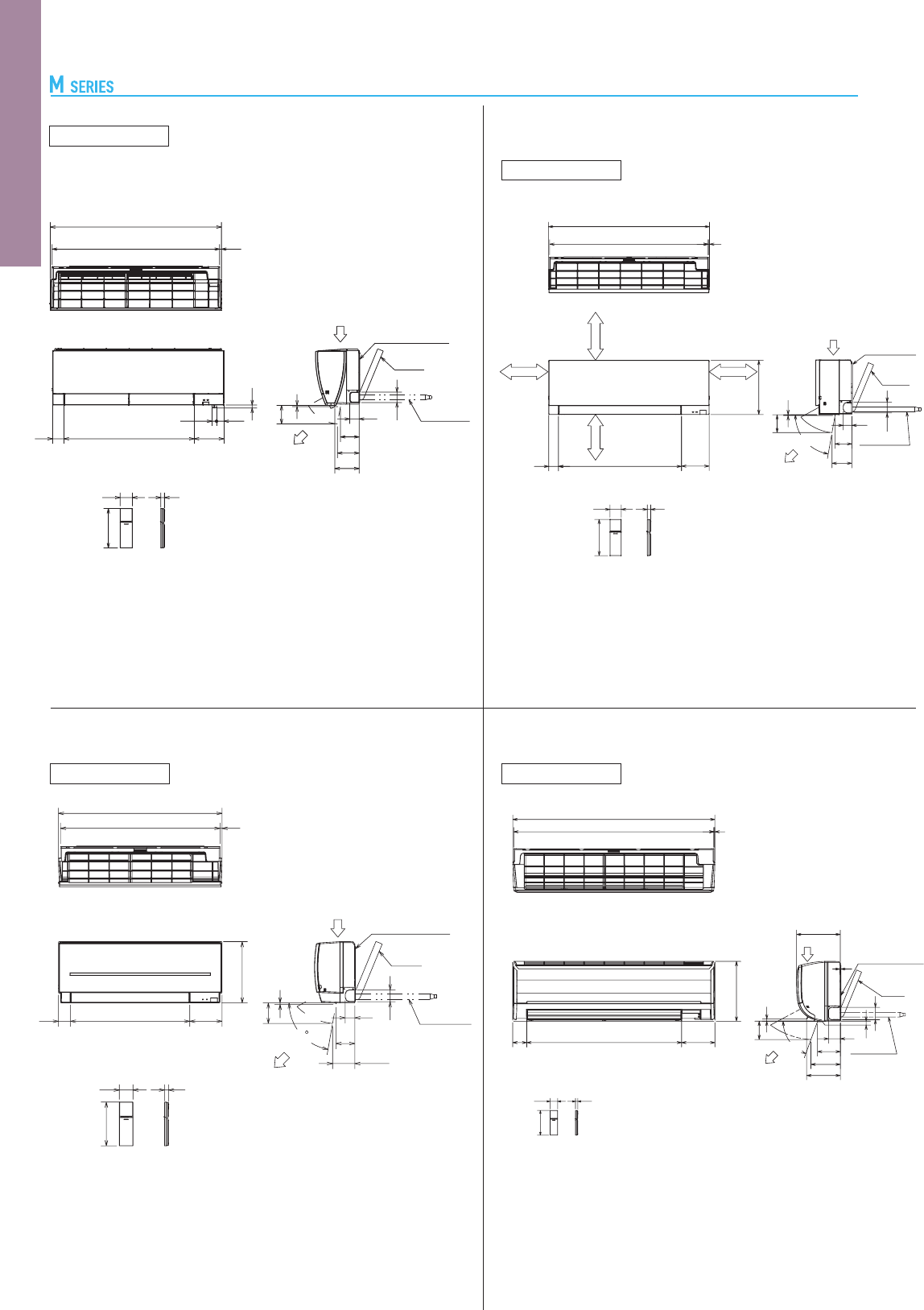
121
Unit : mm
MSZ-HJ60VA MSZ-HJ71VA
INDOOR UNIT
MSZ-SF15VA MSZ-SF20VA
INDOOR UNIT
760
740
10
5
168
56
505
179
250
8
110
41
56
Installation plate
Piping
Drain hose
Air out
60
193
18
MSZ-HJ25VA MSZ-HJ35VA MSZ-HJ50VA
MSZ-DM25VA MSZ-DM35VA
INDOOR UNIT
INDOOR UNIT
MFZ-KJ25VE(2) MFZ-KJ35VE(2) MFZ-KJ50VE(2)
799
923
909
785 7
290
12063049
57
42
7
103
130
100
(
57°)
172
14
140
57 18
46
Air in
Installation plate
Piping
Drain hose
Air out
730
No obstruction
Less than
150mm
More than
100mm
More than
100mm
600
750
47 47
656
47 47
656
Sensor hole
Air in
Liquid pipe
ø6.35 (flared) 1/4
Gas pipe
25/35: ø9.52 (flared) 3/8
50: ø12.7 (flared) 1/2
Drain
Air out
60
70
28
60
30
15
15
131
153
148
215
12
104
127
125
165
303
205
26
Remote controller
19
193
60
7
305
65
65
53 709 161
57
140
18
114
146
100
7
Installation plate
Piping
Drain hose
Air out
Air in
Unit : mm
925
Air in
Air out
51
101
117
132
Installation plate
Piping
Drain hose
905
61 704
60 18
160
39
17
7
100
193
56
25
10
MSZ-FH25VE(2) MSZ-FH35VE(2) MSZ-FH50VE(2)
INDOOR UNIT
External Dimensions
60
193
18
885
875 5
678
158
299
59
7 or more
In case of left,
left back,or
left under piping
(using spacer),
111 or more.
57 or more
35 or more
35 or more
(80°)
7
100
110
94
47
58
Air out
Installation
plate
Piping
Drain hose
Air in
MSZ-SF25VE2(3) MSZ-SF35VE2(3)
MSZ-SF42VE2(3) MSZ-SF50VE2(3)
INDOOR UNIT
INDOOR UNIT
MSZ-GF60VE(2) MSZ-GF71VE(2)
INDOOR UNIT
MSZ-EF18VE2
(3)
(
W
)(
B
)(
S
)
MSZ-EF22VE2
(3)
(
W
)(
B
)(
S
)
MSZ-EF25VE2
(3)
(
W
)(
B
)(
S
)
MSZ-EF35VE2
(3)
(
W
)(
B
)(
S
)
MSZ-EF42VE2
(3)
(
W
)(
B
)(
S
)
MSZ-EF50VE2
(3)
(
W
)(
B
)(
S
)
1090 5
1100
76 843 181
60
193
18
65
67
325
3
100
125
160
(70∞)
238
5
184
12
Air out
Piping
Drain hose
Air in
Installation plate
58
92
47
108.5
100
7
()80
60
193
18
299
577 16061
798
778 10
Installation plate
Piping
Drain hose
Air out
Air in
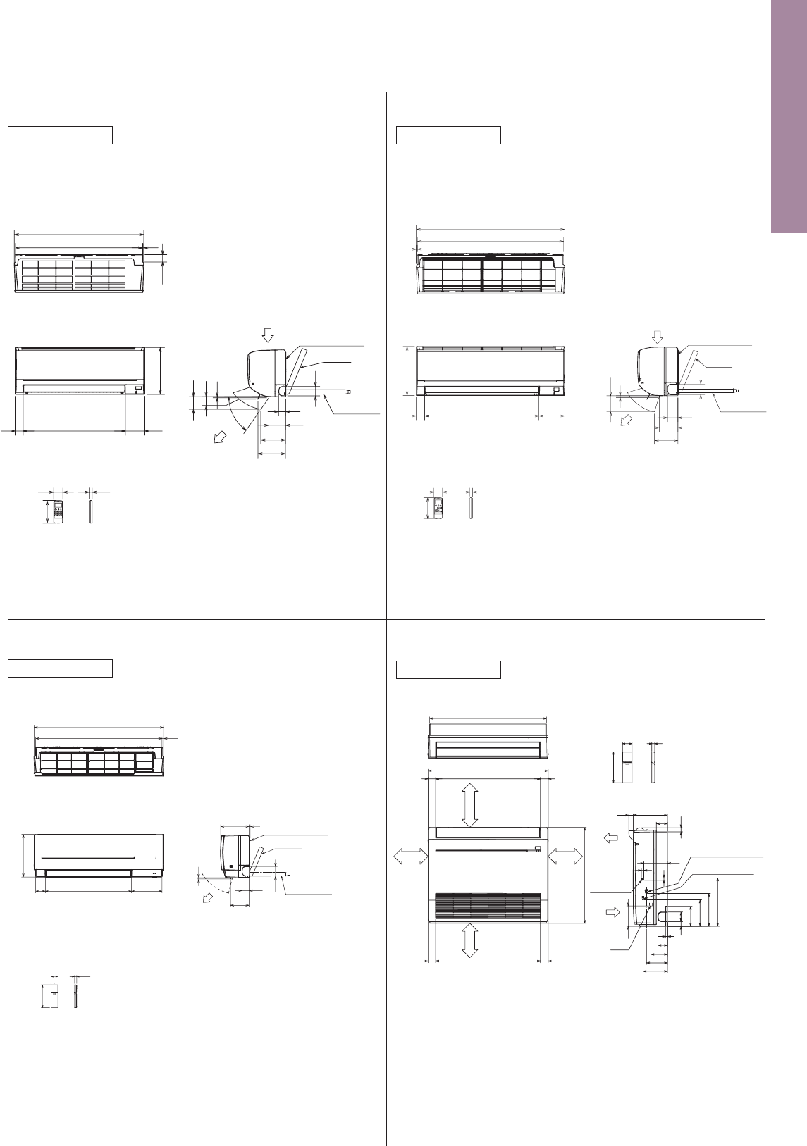
122
Unit : mm
MSZ-HJ60VA MSZ-HJ71VA
INDOOR UNIT
MSZ-SF15VA MSZ-SF20VA
INDOOR UNIT
760
740
10
5
168
56
505
179
250
8
110
41
56
Installation plate
Piping
Drain hose
Air out
60
193
18
MSZ-HJ25VA MSZ-HJ35VA MSZ-HJ50VA
MSZ-DM25VA MSZ-DM35VA
INDOOR UNIT
INDOOR UNIT
MFZ-KJ25VE(2) MFZ-KJ35VE(2) MFZ-KJ50VE(2)
799
923
909
785 7
290
12063049
57
42
7
103
130
100
(
57°)
172
14
140
57 18
46
Air in
Installation plate
Piping
Drain hose
Air out
730
No obstruction
Less than
150mm
More than
100mm
More than
100mm
600
750
47 47
656
47 47
656
Sensor hole
Air in
Liquid pipe
ø6.35 (flared) 1/4
Gas pipe
25/35: ø9.52 (flared) 3/8
50: ø12.7 (flared) 1/2
Drain
Air out
60
70
28
60
30
15
15
131
153
148
215
12
104
127
125
165
303
205
26
Remote controller
19
193
60
7
305
65
65
53 709 161
57
140
18
114
146
100
7
Installation plate
Piping
Drain hose
Air out
Air in
Unit : mm
925
Air in
Air out
51
101
117
132
Installation plate
Piping
Drain hose
905
61 704
60 18
160
39
17
7
100
193
56
25
10
MSZ-FH25VE(2) MSZ-FH35VE(2) MSZ-FH50VE(2)
INDOOR UNIT
External Dimensions
60
193
18
885
875 5
678
158
299
59
7 or more
In case of left,
left back,or
left under piping
(using spacer),
111 or more.
57 or more
35 or more
35 or more
(80°)
7
100
110
94
47
58
Air out
Installation
plate
Piping
Drain hose
Air in
MSZ-SF25VE2(3) MSZ-SF35VE2(3)
MSZ-SF42VE2(3) MSZ-SF50VE2(3)
INDOOR UNIT
INDOOR UNIT
MSZ-GF60VE(2) MSZ-GF71VE(2)
INDOOR UNIT
MSZ-EF18VE2
(3)
(
W
)(
B
)(
S
)
MSZ-EF22VE2
(3)
(
W
)(
B
)(
S
)
MSZ-EF25VE2
(3)
(
W
)(
B
)(
S
)
MSZ-EF35VE2
(3)
(
W
)(
B
)(
S
)
MSZ-EF42VE2
(3)
(
W
)(
B
)(
S
)
MSZ-EF50VE2
(3)
(
W
)(
B
)(
S
)
1090 5
1100
76 843 181
60
193
18
65
67
325
3
100
125
160
(70∞)
238
5
184
12
Air out
Piping
Drain hose
Air in
Installation plate
58
92
47
108.5
100
7
()80
60
193
18
299
577 16061
798
778 10
Installation plate
Piping
Drain hose
Air out
Air in
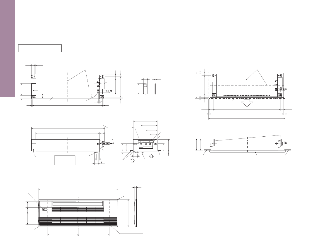
123
Unit : mm
MUZ-HJ25VA MUZ-HJ35VA
MUZ-DM25VA MUZ-DM35VA
OUTDOOR UNIT
MUZ-FH50VE MUZ-FH50VEHZ
MUZ-EF50VE
MUZ-SF50VE MUZ-SF50VEH
MUZ-GF60VE MUZ-GF71VE
MUZ-HJ60VA MUZ-HJ71VA
MUFZ-KJ50VE MUFZ-KJ50VEHZ
OUTDOOR UNIT
10
69
800
302.5
500 Bolt pitch for installation
150
22.3
Handle
550
280
164.5
99.5
170.5
23
Service panel
Service port
285
344.5
44
400
Air in
Air out
Air in
17.5
Bolt pitch for
installation
304-325
40
Liquid refrigerant
pipe joint
Refrigerant pipe
Gas refrigerant
pipe joint
Refrigerant pipe
43
35
2 holes 10 21
Drain hole ø42
MUZ-FH25VE MUZ-FH35VE
MUZ-FH25VEHZ
MUZ-EF25VE
MUZ-EF35VE
MUZ-EF25VEH
MUZ-EF35VEH
MUZ-EF42VE
MUZ-FH35VEHZ
MUZ-SF25VE MUZ-SF25VEH MUZ-SF35VE
MUZ-SF35VEH
MUZ-HJ50VA
MUFZ-KJ25VE
MUFZ-KJ25VEHZ
MUFZ-KJ35VE
MUFZ-KJ35VEHZ
MUZ-SF42VE MUZ-SF42VEH
OUTDOOR UNIT
417.5
40
42
Drain hole
175
500
330
50
Air in
Air out
2-holes 10 21
360
840
109
81
880
452
Service panel
99.5
164.5
195
35
44
Liquid refrigerant
pipe joint
Refrigerant pipe
Gas refrigerant
pipe joint
Refrigerant pipe
41.5
270.3
157.7
43
°
40°
102.7
13.5
538
Air in
Air in
Air out
349.5
55.7
121.4
249
17.9
699
500121
259
Bolt pitch for
installation
294~267
285
19.6
Liquid refrigerant pipe joint
Refrigerant pipe (flared) ø6.35
Gas refrigerant pipe joint
Refrigerant pipe (flared) ø9.52
Drain hole ø33
2-10.3×19.3 Oval hole
Unit : mm
INDOOR UNIT
MLZ-KA25VA MLZ-KA35VA MLZ-KA50VA
Center of ceiling opening, suspension bolt pitch
and grille are located in one position.
Hole position for the
installation of grille
Electrical box
1051 Suspension bolt pitch
Air outlet
Wireless
remote controller
Grille (MLP-440W)
Electrical box
Receiving section
Drain pipe
Display and
receiving section
Ceiling
surface
Liquid pipe
Gas pipe
Drain hose
Pipe cover
Drain pan
Outlet opening area
Drain hose
connecting part
Pipe
cover
308
Suspension bolt pitch
Drain hose
No gaps between
the ceiling surface and grille
R66
CL
CL
0.04m
2
13.549.7
16
16
26
26
58
230
2
2
960
78
360
110
170
244
175
112
116
110
60
25
48
58
(51.6)
180
1102
1200
414
34
15
58 18
158
R6
31
10
0
466.5
466.5
166.5
0
172.4
81.8
173
166.5
Center of ceiling opening,
suspension bolt pitch and grille
are located in one position.
Air outlet
Ceiling surface
Ceiling surface
Suspension bolt M10
Grille
414 Outer side of grille
384 Ceiling opening
308 Suspension bolt pitch
38
38
175
180 or more
54.5
1051 Suspension bolt pitch
1160 Ceiling opening
1200 Outer side of grille
Outlet
2020
54.5
15
15
(Top)
(Front)
(Right side)
(Top)
(Front)
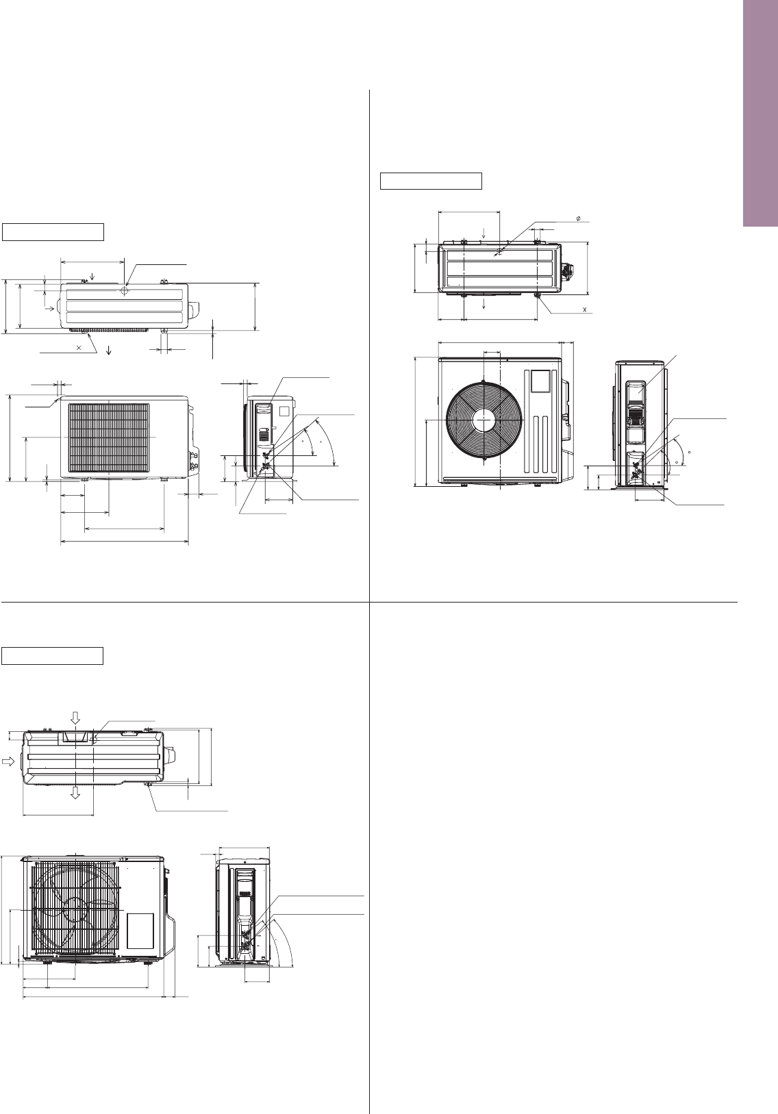
124
Unit : mm
MUZ-HJ25VA MUZ-HJ35VA
MUZ-DM25VA MUZ-DM35VA
OUTDOOR UNIT
MUZ-FH50VE MUZ-FH50VEHZ
MUZ-EF50VE
MUZ-SF50VE MUZ-SF50VEH
MUZ-GF60VE MUZ-GF71VE
MUZ-HJ60VA MUZ-HJ71VA
MUFZ-KJ50VE MUFZ-KJ50VEHZ
OUTDOOR UNIT
10
69
800
302.5
500 Bolt pitch for installation
150
22.3
Handle
550
280
164.5
99.5
170.5
23
Service panel
Service port
285
344.5
44
400
Air in
Air out
Air in
17.5
Bolt pitch for
installation
304-325
40
Liquid refrigerant
pipe joint
Refrigerant pipe
Gas refrigerant
pipe joint
Refrigerant pipe
43
35
2 holes 10 21
Drain hole ø42
MUZ-FH25VE MUZ-FH35VE
MUZ-FH25VEHZ
MUZ-EF25VE
MUZ-EF35VE
MUZ-EF25VEH
MUZ-EF35VEH
MUZ-EF42VE
MUZ-FH35VEHZ
MUZ-SF25VE MUZ-SF25VEH MUZ-SF35VE
MUZ-SF35VEH
MUZ-HJ50VA
MUFZ-KJ25VE
MUFZ-KJ25VEHZ
MUFZ-KJ35VE
MUFZ-KJ35VEHZ
MUZ-SF42VE MUZ-SF42VEH
OUTDOOR UNIT
417.5
40
42
Drain hole
175
500
330
50
Air in
Air out
2-holes 10 21
360
840
109
81
880
452
Service panel
99.5
164.5
195
35
44
Liquid refrigerant
pipe joint
Refrigerant pipe
Gas refrigerant
pipe joint
Refrigerant pipe
41.5
270.3
157.7
43
°
40°
102.7
13.5
538
Air in
Air in
Air out
349.5
55.7
121.4
249
17.9
699
500121
259
Bolt pitch for
installation
294~267
285
19.6
Liquid refrigerant pipe joint
Refrigerant pipe (flared) ø6.35
Gas refrigerant pipe joint
Refrigerant pipe (flared) ø9.52
Drain hole ø33
2-10.3×19.3 Oval hole
Unit : mm
INDOOR UNIT
MLZ-KA25VA MLZ-KA35VA MLZ-KA50VA
Center of ceiling opening, suspension bolt pitch
and grille are located in one position.
Hole position for the
installation of grille
Electrical box
1051 Suspension bolt pitch
Air outlet
Wireless
remote controller
Grille (MLP-440W)
Electrical box
Receiving section
Drain pipe
Display and
receiving section
Ceiling
surface
Liquid pipe
Gas pipe
Drain hose
Pipe cover
Drain pan
Outlet opening area
Drain hose
connecting part
Pipe
cover
308
Suspension bolt pitch
Drain hose
No gaps between
the ceiling surface and grille
R66
CL
CL
0.04m
2
13.549.7
16
16
26
26
58
230
2
2
960
78
360
110
170
244
175
112
116
110
60
25
48
58
(51.6)
180
1102
1200
414
34
15
58 18
158
R6
31
10
0
466.5
466.5
166.5
0
172.4
81.8
173
166.5
Center of ceiling opening,
suspension bolt pitch and grille
are located in one position.
Air outlet
Ceiling surface
Ceiling surface
Suspension bolt M10
Grille
414 Outer side of grille
384 Ceiling opening
308 Suspension bolt pitch
38
38
175
180 or more
54.5
1051 Suspension bolt pitch
1160 Ceiling opening
1200 Outer side of grille
Outlet
2020
54.5
15
15
(Top)
(Front)
(Right side)
(Top)
(Front)
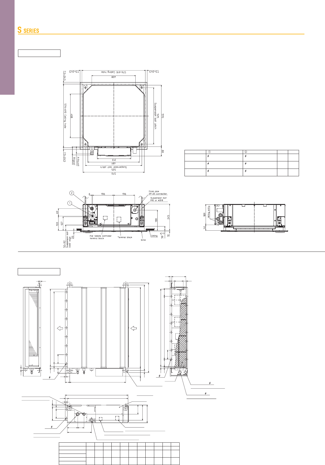
125
Unit : mm
SLZ-KF25VA SLZ-KF35VA
SLZ-KF50VA SLZ-KF60VA
SEZ-KD25VAQ SEZ-KD35VAQ SEZ-KD50VAQ SEZ-KD60VAQ SEZ-KD71VAQ
SEZ-KD25VAL SEZ-KD35VAL SEZ-KD50VAL SEZ-KD60VAL SEZ-KD71VAL
24
20
16
900
700
500
9
7
5
1060
860
660
LJHK
SEZ-KD71VAL/VAQ
SEZ-KD60VAL/VAQ
SEZ-KD50VAL/VAQ
SEZ-KD35VAL/VAQ
700 752 798660 7600 800
1198
998
AModel
SEZ-KD25VAL/VAQ
1152
952
B
1100
900
C
1060
860
D
11
9
E
1000
800
F
1200
1000
G
Notes:
1. Use M10 bolts for suspension (purchase locally).
2. Keep service space for maintenance at the bottom.
3. This chart is based on the SEZ-KD50VAL/VAQ, which has three fans.
SEZ-KD25, 35VAL/VAQ has two fans, and SEZ-KD60, 71VAL/VAQ has four fans.
4. If an inlet duct is used, remove the air filter supplied with the unit,
and install a locally purchased filter on the suction side.
Air
outlet
Air
inlet
Terminal block
(Remote controller transmission line)
Drain pipe(Spontaneous draining)
Refrigerant piping
flare connection (gas)
Refrigerant piping
flare connection (liquid)
Terminal block
(Indoor/outdoor connecting line)
Suspension bolt hole
4-14X30 Slot
Air filter
Control box
2XE- 2.9
2X2- 2.9
L- 2.9
Knockout hole 27
(Indoor/outdoor connecting line)
Knockout hole 27
(Remote controller transmission line)
10
170
57
15
20
100
100X(E-1)=F
30
D (Duct)
625
(Suspension bolt pitch)
90
A
23
B (Suspension bolt pitch)
C
23 677
700
25100
23
150
(Duct)
11670
270
102
25
49
10
88
100
100XJ=K 8812
12
37
100
20 157.5
20 H
200
37
INDOOR UNIT
INDOOR UNIT
63mm
63mm
SLZ-KF50VA
SLZ-KF35VA
SLZ-KF25VA
Models
6.35mm
Refrigerent pipe (liquid)
Refrigerent pipe (gas)
flared connection 1/4F
9.52mm
flared connection 3/8F
flared connection 1/4F
12.7mm
flared connection 1/2F
flared connection 1/4F
15.88mm
flared connection 5/8F
AB
63mm
72mm
78mm
78mm
SLZ-KF60VA
6.35mm
6.35mm
Unit : mm
10
69
800
302.5
500 Bolt pitch for installation
150
22.3
Handle
550
280
164.5
99.5
170.5
23
Service panel
Service port
285
344.5
44
400
Air in
Air out
Air in
17.5
Bolt pitch for
installation
304~325
40
Liquid refrigerant pipe joint
Refrigerant pipe (flared)
Gas refrigerant pipe joint
Refrigerant pipe (flared)
43
35
2 holes 10X21
Drain hole
SUZ-KA25VA5 SUZ-KA35VA5
OUTDOOR UNIT
SUZ-KA50VA5 SUZ-KA60VA5 SUZ-KA71VA5
OUTDOOR UNIT
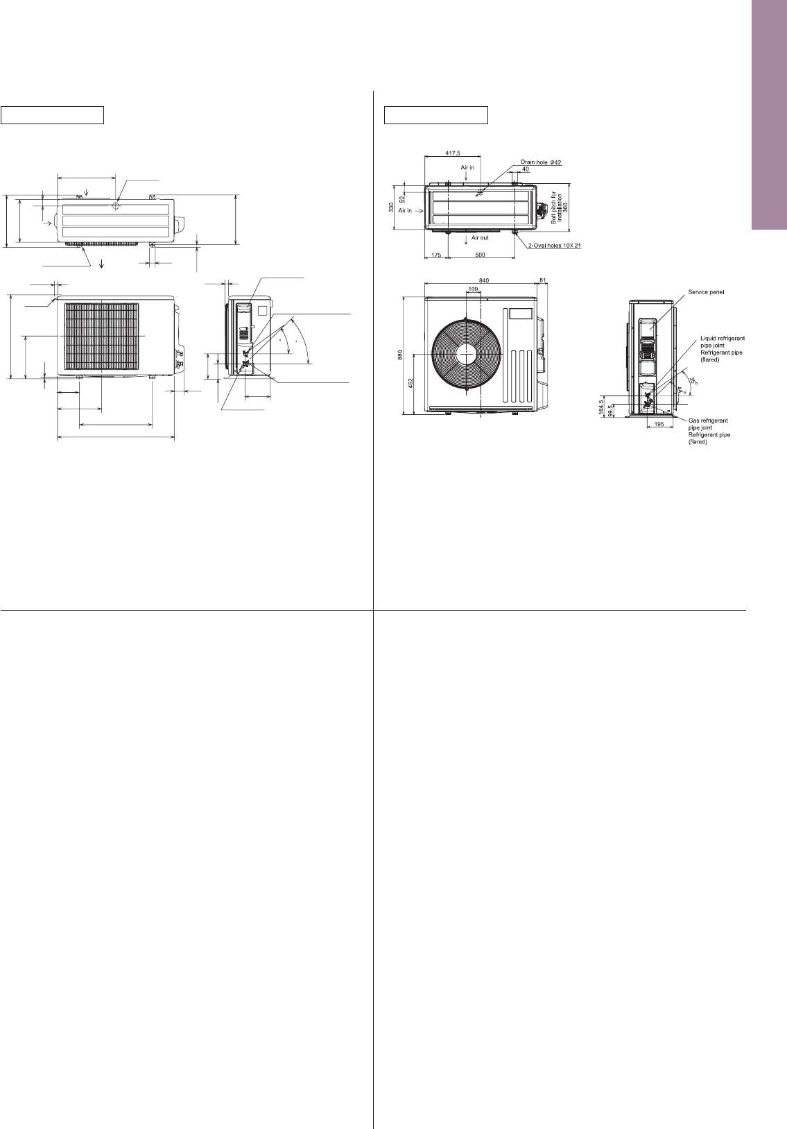
126
Unit : mm
SLZ-KF25VA SLZ-KF35VA
SLZ-KF50VA SLZ-KF60VA
SEZ-KD25VAQ SEZ-KD35VAQ SEZ-KD50VAQ SEZ-KD60VAQ SEZ-KD71VAQ
SEZ-KD25VAL SEZ-KD35VAL SEZ-KD50VAL SEZ-KD60VAL SEZ-KD71VAL
24
20
16
900
700
500
9
7
5
1060
860
660
LJHK
SEZ-KD71VAL/VAQ
SEZ-KD60VAL/VAQ
SEZ-KD50VAL/VAQ
SEZ-KD35VAL/VAQ
700 752 798660 7600 800
1198
998
AModel
SEZ-KD25VAL/VAQ
1152
952
B
1100
900
C
1060
860
D
11
9
E
1000
800
F
1200
1000
G
Notes:
1. Use M10 bolts for suspension (purchase locally).
2. Keep service space for maintenance at the bottom.
3. This chart is based on the SEZ-KD50VAL/VAQ, which has three fans.
SEZ-KD25, 35VAL/VAQ has two fans, and SEZ-KD60, 71VAL/VAQ has four fans.
4. If an inlet duct is used, remove the air filter supplied with the unit,
and install a locally purchased filter on the suction side.
Air
outlet
Air
inlet
Terminal block
(Remote controller transmission line)
Drain pipe(Spontaneous draining)
Refrigerant piping
flare connection (gas)
Refrigerant piping
flare connection (liquid)
Terminal block
(Indoor/outdoor connecting line)
Suspension bolt hole
4-14X30 Slot
Air filter
Control box
2XE- 2.9
2X2- 2.9
L- 2.9
Knockout hole 27
(Indoor/outdoor connecting line)
Knockout hole 27
(Remote controller transmission line)
10
170
57
15
20
100
100X(E-1)=F
30
D (Duct)
625
(Suspension bolt pitch)
90
A
23
B (Suspension bolt pitch)
C
23 677
700
25100
23
150
(Duct)
11670
270
102
25
49
10
88
100
100XJ=K 8812
12
37
100
20 157.5
20 H
200
37
INDOOR UNIT
INDOOR UNIT
63mm
63mm
SLZ-KF50VA
SLZ-KF35VA
SLZ-KF25VA
Models
6.35mm
Refrigerent pipe (liquid)
Refrigerent pipe (gas)
flared connection 1/4F
9.52mm
flared connection 3/8F
flared connection 1/4F
12.7mm
flared connection 1/2F
flared connection 1/4F
15.88mm
flared connection 5/8F
AB
63mm
72mm
78mm
78mm
SLZ-KF60VA
6.35mm
6.35mm
Unit : mm
10
69
800
302.5
500 Bolt pitch for installation
150
22.3
Handle
550
280
164.5
99.5
170.5
23
Service panel
Service port
285
344.5
44
400
Air in
Air out
Air in
17.5
Bolt pitch for
installation
304~325
40
Liquid refrigerant pipe joint
Refrigerant pipe (flared)
Gas refrigerant pipe joint
Refrigerant pipe (flared)
43
35
2 holes 10X21
Drain hole
SUZ-KA25VA5 SUZ-KA35VA5
OUTDOOR UNIT
SUZ-KA50VA5 SUZ-KA60VA5 SUZ-KA71VA5
OUTDOOR UNIT
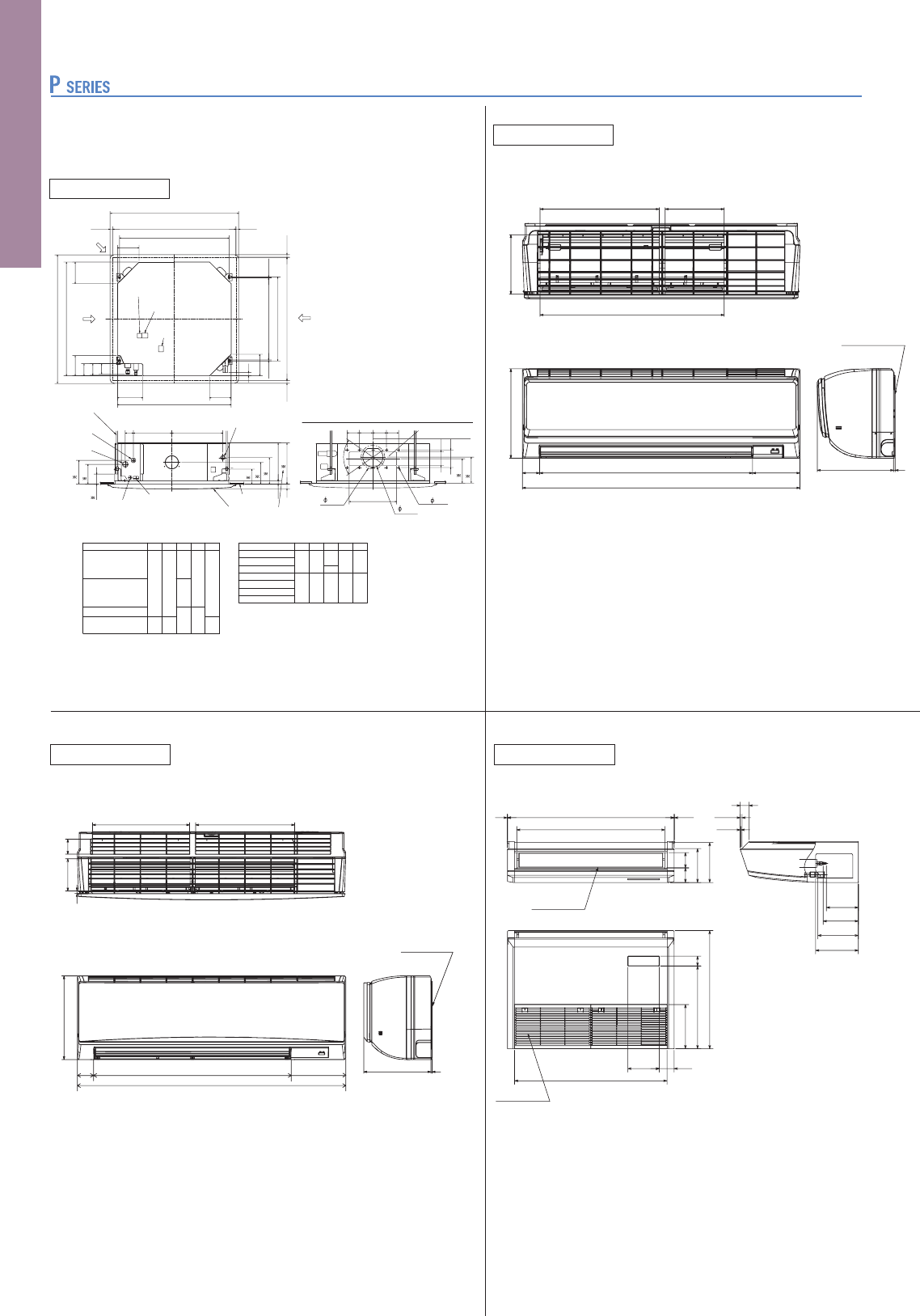
127
Unit : mm
Ceiling hole
Branch duct hole
Indoor unit/Outdoor
unit connecting
terminal block
Indoor power supply
terminal block(optional part)
Branch duct hole
Fresh air
intake hole
Ceiling hole
Suspension bolt pitch
Suspension bolt pitch
Remote controller
terminal block
(7.5)(7.5)
605
620
160
160
160
840
150
90
C
D
840
187.5
20~45
860~910
20~45
810
20~45
860~910
20~45
24
160
950
Cut out hole
Cut out hole
Burring hole pitch
Burring hole
175
167
130
100
70
155
350
90 100 100 90
Detail connecting of branch duct
14- 2.8
150
37728460
Drain pipe
Ceiling
Grille
Power supply wire,
Indoor unit/Outdoor unit
connecting wire entry
Control wire entry
Keep approximately
10 to 15mm space
between unit ceiling
and ceiling slab.
Suspension bolt
M10 or W3/8
A
17
+5
0
B35
190
156
105
140
50~70
Suspension bolt
lower edge
170
Models
BA CDE
241258
80
87
74
400
298
85 77
440
281
PLA-RP35/50BA
PLA-RP60BA
PLA-RP71BA
PLA-RP35BA PLA-RP50BA PLA-RP60BA PLA-RP71BA
PLA-RP100BA PLA-RP125BA PLA-RP140BA2
PLA-ZRP35BA PLA-ZRP50BA PLA-ZRP60BA PLA-ZRP71BA
PLA-ZRP100BA PLA-ZRP125BA PLA-ZRP140BA
INDOOR UNIT
950
Refrigerant pipe
Refrigerant pipe
Air outlet
Air intake
84 88
195
230
57
254
476
680
182 85
878
960 22
853
When drain socket
is installed
233
5
10
51
246
(Drainage)
(gas
(liquid
184
203
PCA-RP35KAQ PCA-RP50KAQ
INDOOR UNIT
(
(
(
(
PKA-RP60KAL PKA-RP71KAL PKA-RP100KAL
INDOOR UNIT
65.2
423.7
1170
431.7
11
140.3
365
5295
Top side
Front side
Mounting board
Right side
74
(855)
241
PKA-RP35HAL PKA-RP50HAL
INDOOR UNIT
197
387
192
599
Top side
Front side
155
688
898
55
295
Right side
Mounting board
249
5
(liquid)
(gas)
PLA-RP100,125BA
PLA-RP140BA2
Models
BACDE
PLA-ZRP35BA
PLA-ZRP50BA
PLA-ZRP60BA
PLA-ZRP71BA
PLA-ZRP100BA
PLA-ZRP125BA
PLA-ZRP140BA
241
281
258
298
74
77
400
440
80
87
85
Unit : mm
INDOOR UNIT
When drain socket
is installed
(Drainage)
(
(
PCA-RP100KAQ PCA-RP125KAQ PCA-RP140KAQ
233
5
10
51
246
180
200
236
84 88
195
230
57
254
476
680
182 85
1518
1600 22
1493
Air outlet
Air intake
(gas)
(liquid)
PCA-RP60KAQ PCA-RP71KAQ
INDOOR UNIT
Air intake
Air outlet
84 88
195
230
57
254
476
680
182 85
1198
1280 2
2
1173
When drain socket
is installed
233
5
10
51
246
A
B
236
(Drainage)
(gas)
(liquid)
A
B
60
179
203
71
180
200
(
(
PSA-RP71KA PSA-RP100KA PSA-RP125KA PSA-RP140KA
INDOOR UNIT
PCA-RP71HAQ
INDOOR UNIT
<Suspension bolt pitch>
<Flexible hose(accessory)>
Terminal block box
Inspection port
(pipe sensor)
<Air outlet>
<Suspension bolt pitch>
<Air outlet>
2
1
3
Flexible hose(accessory) Drainage pipe connection
Refrigerant pipe connection(gas pipe side/flared connection)
Electrical box
<gas>
<liquid>
Refrigerant pipe connection(liquid pipe side/flared connection)
Suspension bolt
1224
1180
75
1136
986
70
243
254
175
197
110
21
13015
110102
32080
75
70~90
650
13
289
75
280
495
43
295
260
240
Knockout hole for wiring 27
(Provided on both sides)
Knockout hole for refrigerant and drainage
90×60 oval (Provided on both sides)
Controller
Metal fixture
against overturning
Knockout hole
for branch duct
Front side
Rear side
240
10
38
38
15
111
115
70
260
600
50
360
310
10
125
340
130
132
100
370
40
520
40
10
20
129 71
130 140
260
820
1900
599
181
834
524
30
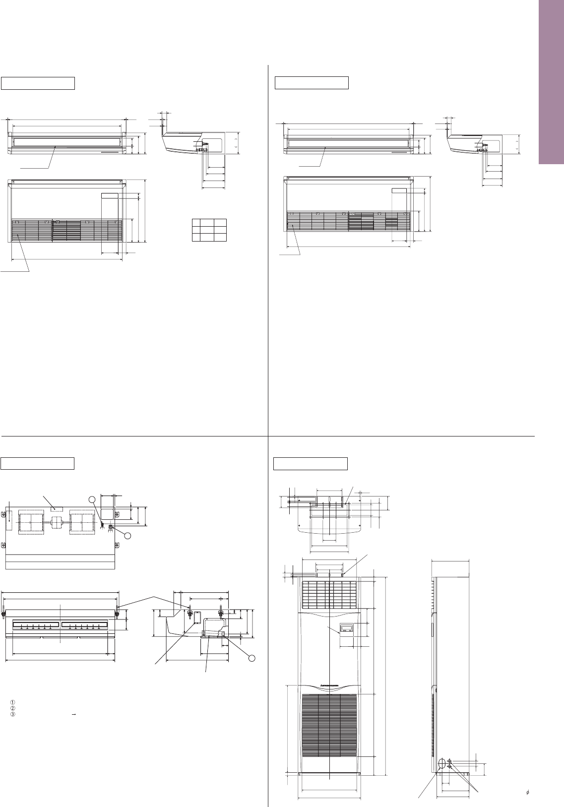
128
Unit : mm
Ceiling hole
Branch duct hole
Indoor unit/Outdoor
unit connecting
terminal block
Indoor power supply
terminal block(optional part)
Branch duct hole
Fresh air
intake hole
Ceiling hole
Suspension bolt pitch
Suspension bolt pitch
Remote controller
terminal block
(7.5)(7.5)
605
620
160
160
160
840
150
90
C
D
840
187.5
20~45
860~910
20~45
810
20~45
860~910
20~45
24
160
950
Cut out hole
Cut out hole
Burring hole pitch
Burring hole
175
167
130
100
70
155
350
90 100 100 90
Detail connecting of branch duct
14- 2.8
150
37728460
Drain pipe
Ceiling
Grille
Power supply wire,
Indoor unit/Outdoor unit
connecting wire entry
Control wire entry
Keep approximately
10 to 15mm space
between unit ceiling
and ceiling slab.
Suspension bolt
M10 or W3/8
A
17
+5
0
B35
190
156
105
140
50~70
Suspension bolt
lower edge
170
Models
BA CDE
241258
80
87
74
400
298
85 77
440
281
PLA-RP35/50BA
PLA-RP60BA
PLA-RP71BA
PLA-RP35BA PLA-RP50BA PLA-RP60BA PLA-RP71BA
PLA-RP100BA PLA-RP125BA PLA-RP140BA2
PLA-ZRP35BA PLA-ZRP50BA PLA-ZRP60BA PLA-ZRP71BA
PLA-ZRP100BA PLA-ZRP125BA PLA-ZRP140BA
INDOOR UNIT
950
Refrigerant pipe
Refrigerant pipe
Air outlet
Air intake
84 88
195
230
57
254
476
680
182 85
878
960 22
853
When drain socket
is installed
233
5
10
51
246
(Drainage)
(gas
(liquid
184
203
PCA-RP35KAQ PCA-RP50KAQ
INDOOR UNIT
(
(
(
(
PKA-RP60KAL PKA-RP71KAL PKA-RP100KAL
INDOOR UNIT
65.2
423.7
1170
431.7
11
140.3
365
5295
Top side
Front side
Mounting board
Right side
74
(855)
241
PKA-RP35HAL PKA-RP50HAL
INDOOR UNIT
197
387
192
599
Top side
Front side
155
688
898
55
295
Right side
Mounting board
249
5
(liquid)
(gas)
PLA-RP100,125BA
PLA-RP140BA2
Models
BACDE
PLA-ZRP35BA
PLA-ZRP50BA
PLA-ZRP60BA
PLA-ZRP71BA
PLA-ZRP100BA
PLA-ZRP125BA
PLA-ZRP140BA
241
281
258
298
74
77
400
440
80
87
85
Unit : mm
INDOOR UNIT
When drain socket
is installed
(Drainage)
(
(
PCA-RP100KAQ PCA-RP125KAQ PCA-RP140KAQ
233
5
10
51
246
180
200
236
84 88
195
230
57
254
476
680
182 85
1518
1600 22
1493
Air outlet
Air intake
(gas)
(liquid)
PCA-RP60KAQ PCA-RP71KAQ
INDOOR UNIT
Air intake
Air outlet
84 88
195
230
57
254
476
680
182 85
1198
1280 2
2
1173
When drain socket
is installed
233
5
10
51
246
A
B
236
(Drainage)
(gas)
(liquid)
A
B
60
179
203
71
180
200
(
(
PSA-RP71KA PSA-RP100KA PSA-RP125KA PSA-RP140KA
INDOOR UNIT
PCA-RP71HAQ
INDOOR UNIT
<Suspension bolt pitch>
<Flexible hose(accessory)>
Terminal block box
Inspection port
(pipe sensor)
<Air outlet>
<Suspension bolt pitch>
<Air outlet>
2
1
3
Flexible hose(accessory) Drainage pipe connection
Refrigerant pipe connection(gas pipe side/flared connection)
Electrical box
<gas>
<liquid>
Refrigerant pipe connection(liquid pipe side/flared connection)
Suspension bolt
1224
1180
75
1136
986
70
243
254
175
197
110
21
13015
110102
32080
75
70~90
650
13
289
75
280
495
43
295
260
240
Knockout hole for wiring 27
(Provided on both sides)
Knockout hole for refrigerant and drainage
90×60 oval (Provided on both sides)
Controller
Metal fixture
against overturning
Knockout hole
for branch duct
Front side
Rear side
240
10
38
38
15
111
115
70
260
600
50
360
310
10
125
340
130
132
100
370
40
520
40
10
20
129 71
130 140
260
820
1900
599
181
834
524
30
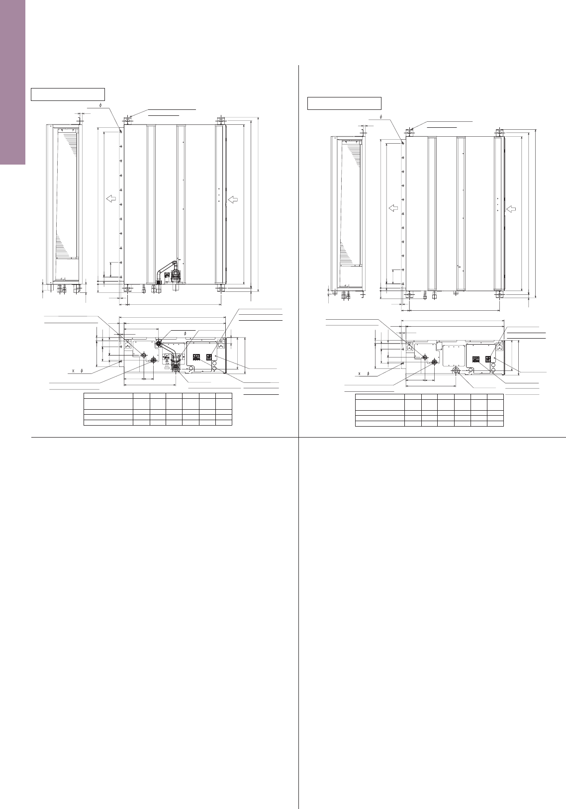
129
Unit : mm
PEAD-RP35JAQ PEAD-RP50JAQ PEAD-RP60JAQ PEAD-RP71JAQ
PEAD-RP100JAQ PEAD-RP125JAQ PEAD-RP140JAQ
INDOOR UNIT
Model
PEAD-RP140JAQ
PEAD-RP100,125JAQ
PEAD-RP60,71JAQ
PEAD-RP35,50JAQ
A
900
1100
1400
1600
954
B
1154
1454
1654
860
D
1060
1360
1560
9
E
11
14
16
1200
C
1500
1700
1000
1500
1300
1000
F
800
Suspension bolt hole
4-14x30 Slot
Air
outlet
Air
inlet
2xE- 2.9
40
15
58
57
10
100
100x(E-1)=F
A
B(Suspension bolt pitch)
C
23
30
57
20
D (Duct)
2 2- 2.9
Refrigerant piping
Flare connection (liquid)
Refrigerant piping
Flare connection (gas)
Drain pump
Control box
Terminal block
(Indoor/Outdoor
connecting line)
Terminal block
(Remote controller
transmission line)
Drain pipe
(Spontaneous draining)
Drain pipe
(O.D. 32)
250
12233
40
23
10
238
32 700
732
136
67
356
100
41
217
643(Suspension bolt pitch)
178(Duct)
PEAD-RP35JALQ PEAD-RP50JALQ PEAD-RP60JALQ
PEAD-RP71JALQ PEAD-RP100JALQ PEAD-RP125JALQ
PEAD-RP140JALQ
INDOOR UNIT
Model
PEAD-RP140JALQ
PEAD-RP100,125JALQ
PEAD-RP60,71JALQ
PEAD-RP35,50JALQ
A
900
1100
1400
1600
954
B
1154
1454
1654
860
D
1060
1360
1560
9
E
11
14
16
1200
C
1500
1700
1000
Suspension bolt hole
4-14x30 Slot
Air
outlet
Air
inlet
2xE- 2.9
15
24
57
10
100
100x(E-1)=F
A
B(Suspension bolt pitch)
C
23
30
57
20
D (Duct)
Drain pipe
2 2- 2.9
Refrigerant piping
Flare connection (liquid)
Refrigerant piping
Flare connection (gas)
Control box
Terminal block
(Indoor/Outdoor
connecting line)
Terminal block
(Remote controller
transmission line)
250
33 122
40
23
10
32 700
732
136
67
356
100
217
643(Suspension bolt pitch)
1500
1300
1000
F
800
178(Duct)
Unit : mm
PEA-RP400GAQ PEA-RP500GAQ
INDOOR UNIT
45
Refrigerant pipe
Refrigerant pipe (gas)
Return air sensor
(2 places)
Drain
24- 3.1
36- 3 HOLES
Left view
Front view
Top view
Return air
Supply air
4- 15
<For hanging bolt M12>
[Field supply]
Return-air
duct flange
Control box
Fresh-air intake
duct flange
A
Rubber bushing
<Remote controller wiring>
Rubber bushing
<Power supply wiring>
Rubber bushing
<Outdoor unit connection wiring>
A
<Accessory>
Pipe cover
...................
4pcs.
(For dew condensation prevention of local piping and unit connection)
Remote controller
.......
1pc.
81
11715611 7
10
20 1840
10
40
60
60
61
60
4040
1800
1880
50 664
525
22
102
22.5
120
4X120(=480)
22.5
595
1824
50
764
2801125395
340 18822
1947
570
40 130 130 40
10
33
29
130
12X130(=1560)
29
149 1618
100
42.5
130
8X130(=1040)42.5
10
203320141
20
42559
700
39
Rubber bushing
<Remote
controller wiring>
Rubber bushing
<Outdoor unit
connection wiring>
Rubber bushing
<Power supply
wiring>
A
A
4- 12
Drain
Top view
Control box
22- 3.1
<For hanging bolt M10>
[Field supply]
Return air
duct flange
Fresh-air
intake duct
flange
26- 3 Holes
Left view
Supply air
Return air
Front view
Return air
sensor
<Accessory>
Pipe cover
....................
2pcs.
(For dew condensation prevention of local piping and unit connection)
Remote controller
.........
1pc.
Refrigerant pipe
Refrigerant pipe
42
144145
75
55
70 129
124
131
50 530
34
130
9525011
10
66
1302
1484
7x130(=910)
130
45
45
200
20
100
20
199
40
1500
462
66 9X130(=1170)
10
25 100 100 25
10 10
1540
40146040
255 205
376
1000
1600
73262
400
39 565
54
634
35
130
89
330 22
130
35
PEA-RP250GAQ
INDOOR UNIT
PEA-RP200GAQ
INDOOR UNIT
Return air
sensor
A
Rubber bushing <Remote
controller wiring>
Rubber bushing
<Outdoor unit
connection wiring>
Rubber bushing
<Power supply wiring>
A
4- 12
Drain
Top view
Control box
Return-air
duct flange
Fresh-air
intake duct
flange
<For hanging bolt M10>
[pwehase locally]
22- 3.1
24- 3 Holes
Refrigerant pipe
(liquid)
Refrigerant pipe
(gas)
<Accessory>
Pipe cover
....................
2pcs.
(For dew condensation prevention of local piping and unit connection)
Remote controller
........
1pc.
Return air
Left view
Supply air
Front view
75
55
12970
42
124 34
131
530
50
9525011
7x130(=910)
10
130
130
45
45
31 31
1102
200
10
8x130(=1040)
1300
20
199
100
40
20
462
144
1284
400
155 1000 105
40 1260 40
1340
1400
56539
22330
145
89
35
130
130
35
634
262 73
10
54
10
376
2510010025
(gas)
(Liquid)
(liquid)
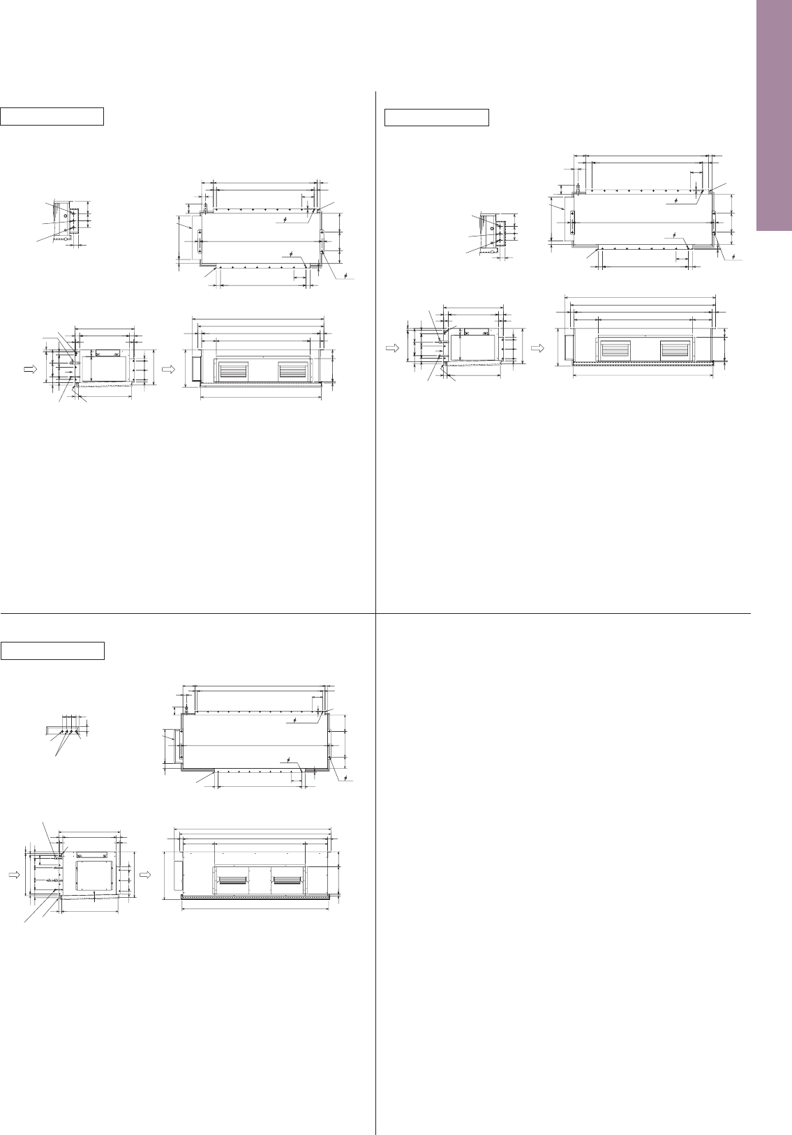
130
Unit : mm
PEAD-RP35JAQ PEAD-RP50JAQ PEAD-RP60JAQ PEAD-RP71JAQ
PEAD-RP100JAQ PEAD-RP125JAQ PEAD-RP140JAQ
INDOOR UNIT
Model
PEAD-RP140JAQ
PEAD-RP100,125JAQ
PEAD-RP60,71JAQ
PEAD-RP35,50JAQ
A
900
1100
1400
1600
954
B
1154
1454
1654
860
D
1060
1360
1560
9
E
11
14
16
1200
C
1500
1700
1000
1500
1300
1000
F
800
Suspension bolt hole
4-14x30 Slot
Air
outlet
Air
inlet
2xE- 2.9
40
15
58
57
10
100
100x(E-1)=F
A
B(Suspension bolt pitch)
C
23
30
57
20
D (Duct)
2 2- 2.9
Refrigerant piping
Flare connection (liquid)
Refrigerant piping
Flare connection (gas)
Drain pump
Control box
Terminal block
(Indoor/Outdoor
connecting line)
Terminal block
(Remote controller
transmission line)
Drain pipe
(Spontaneous draining)
Drain pipe
(O.D. 32)
250
12233
40
23
10
238
32 700
732
136
67
356
100
41
217
643(Suspension bolt pitch)
178(Duct)
PEAD-RP35JALQ PEAD-RP50JALQ PEAD-RP60JALQ
PEAD-RP71JALQ PEAD-RP100JALQ PEAD-RP125JALQ
PEAD-RP140JALQ
INDOOR UNIT
Model
PEAD-RP140JALQ
PEAD-RP100,125JALQ
PEAD-RP60,71JALQ
PEAD-RP35,50JALQ
A
900
1100
1400
1600
954
B
1154
1454
1654
860
D
1060
1360
1560
9
E
11
14
16
1200
C
1500
1700
1000
Suspension bolt hole
4-14x30 Slot
Air
outlet
Air
inlet
2xE- 2.9
15
24
57
10
100
100x(E-1)=F
A
B(Suspension bolt pitch)
C
23
30
57
20
D (Duct)
Drain pipe
2 2- 2.9
Refrigerant piping
Flare connection (liquid)
Refrigerant piping
Flare connection (gas)
Control box
Terminal block
(Indoor/Outdoor
connecting line)
Terminal block
(Remote controller
transmission line)
250
33 122
40
23
10
32 700
732
136
67
356
100
217
643(Suspension bolt pitch)
1500
1300
1000
F
800
178(Duct)
Unit : mm
PEA-RP400GAQ PEA-RP500GAQ
INDOOR UNIT
45
Refrigerant pipe
Refrigerant pipe (gas)
Return air sensor
(2 places)
Drain
24- 3.1
36- 3 HOLES
Left view
Front view
Top view
Return air
Supply air
4- 15
<For hanging bolt M12>
[Field supply]
Return-air
duct flange
Control box
Fresh-air intake
duct flange
A
Rubber bushing
<Remote controller wiring>
Rubber bushing
<Power supply wiring>
Rubber bushing
<Outdoor unit connection wiring>
A
<Accessory>
Pipe cover
...................
4pcs.
(For dew condensation prevention of local piping and unit connection)
Remote controller
.......
1pc.
81
11715611 7
10
20 1840
10
40
60
60
61
60
4040
1800
1880
50 664
525
22
102
22.5
120
4X120(=480)
22.5
595
1824
50
764
2801125395
340 18822
1947
570
40 130 130 40
10
33
29
130
12X130(=1560)
29
149 1618
100
42.5
130
8X130(=1040)42.5
10
203320141
20
42559
700
39
Rubber bushing
<Remote
controller wiring>
Rubber bushing
<Outdoor unit
connection wiring>
Rubber bushing
<Power supply
wiring>
A
A
4- 12
Drain
Top view
Control box
22- 3.1
<For hanging bolt M10>
[Field supply]
Return air
duct flange
Fresh-air
intake duct
flange
26- 3 Holes
Left view
Supply air
Return air
Front view
Return air
sensor
<Accessory>
Pipe cover
....................
2pcs.
(For dew condensation prevention of local piping and unit connection)
Remote controller
.........
1pc.
Refrigerant pipe
Refrigerant pipe
42
144145
75
55
70 129
124
131
50 530
34
130
9525011
10
66
1302
1484
7x130(=910)
130
45
45
200
20
100
20
199
40
1500
462
66 9X130(=1170)
10
25 100 100 25
10 10
1540
40146040
255 205
376
1000
1600
73262
400
39 565
54
634
35
130
89
330 22
130
35
PEA-RP250GAQ
INDOOR UNIT
PEA-RP200GAQ
INDOOR UNIT
Return air
sensor
A
Rubber bushing <Remote
controller wiring>
Rubber bushing
<Outdoor unit
connection wiring>
Rubber bushing
<Power supply wiring>
A
4- 12
Drain
Top view
Control box
Return-air
duct flange
Fresh-air
intake duct
flange
<For hanging bolt M10>
[pwehase locally]
22- 3.1
24- 3 Holes
Refrigerant pipe
(liquid)
Refrigerant pipe
(gas)
<Accessory>
Pipe cover
....................
2pcs.
(For dew condensation prevention of local piping and unit connection)
Remote controller
........
1pc.
Return air
Left view
Supply air
Front view
75
55
12970
42
124 34
131
530
50
9525011
7x130(=910)
10
130
130
45
45
31 31
1102
200
10
8x130(=1040)
1300
20
199
100
40
20
462
144
1284
400
155 1000 105
40 1260 40
1340
1400
56539
22330
145
89
35
130
130
35
634
262 73
10
54
10
376
2510010025
(gas)
(Liquid)
(liquid)

131
Unit : mm
PUHZ-ZRP35VKA PUHZ-ZRP50VKA
OUTDOOR UNIT
PUHZ-ZRP60VHA PUHZ-ZRP71VHA
OUTDOOR UNIT
322
950
473
943
23
447
431
673
2
1
Handle for moving
Handle for moving
Service panel
Earth terminal
Left:Power supply wiring
Right : Indoor / Outdoor wiring
Terminal connections
Rear piping cover
Front piping cover
40
54
28 370 19
417
53
57 41
600 175175
330
Rear air intake
Air discharge
Side air intake
Installation Feet
2 U-shaped notched holes
(Foundation Bolt M10)
2-12 36 oval holes
(foundation bolt M10)
30
PUHZ-SHW80VHA PUHZ-SHW112VHA
PUHZ-SHW112YHA PUHZ-SHW140YHA
OUTDOOR UNIT
...
Refrigerant gas pipe connection (flare)
...
Refrigerant liquid pipe connection (flare)
...
Indicates stop valve connection location.
PUHZ-ZRP100VKA2 PUHZ-ZRP125VKA2 PUHZ-ZRP140VKA2
PUHZ-ZRP100YKA2 PUHZ-ZRP125YKA2 PUHZ-ZRP140YKA2
OUTDOOR UNIT
Refrigerant GAS pipe
connection
2
...
Indication of STOP VALVE connection location.
1
...
Indication of Terminal connection location.
1
Refrigerant LIQUID pipe
connection
Handle for moving
Service panel
Air Intake
Front piping cover
...
Refrigerant gas pipe connection (flare)
...
Refrigerant liquid pipe connection (flare)
...
Indicates stop valve connection location.
Front piping cover
Rear piping cover
Air Discharge
Rear Air Intake
Side Air Intake
600175 175
330
417
42
66
53 56
45
(19)28 370
2-U Shaped notched holes
(Foundation Bolt M10)
2-12 x 36 Oval holes
(Foundation Bolt M10)
Installation Feet
30
23
SHW·VHA
SHW·YHA
1079
A
930
Handle for moving
Service panel
A
2
1
1 443
1 447
635
371
1350
322
950
Handle for moving
Handle
for
moving
Earth terminal
Terminal connection
Left ····Power supply wiring
Right··· Indoor/Outdoor wiring
Service port
Connection for
gas pipe
Connection for
liquid pipe
FLARE
6.35 (1/4F)
FLARE
12.7 (1/2F)
Service panel
for charge plug
Service panel
Earth terminal
( )
Terminal connection
Left
Power supply wiring
Right
Indoor/Outdoor wiring
Air discharge
Air intake
Air intake
oval hole
4-10×21
drain hole
42
360
330
32.5
300
40
404.5
48
Handle for moving
Installation bolt pitch
22.3
630
320
8.5
809
500
310
154.5
62
PUHZ-ZRP100~140VKA2.UK
PUHZ-ZRP100~140YK
A2.UK
PUHZ-ZRP100~140YK
A2.UK
Model
Model
450
450
C
442
442
B
919
1067
A
Rear Air Intake
Handle for moving
Installation feet
Air Discharge
Side Air Intake
2-U Shaped notched holes
(foundation bolt M10)
2-12×36 Oval holes
(foundation bolt M10)
225
362
1050
Earth terminal
75
56
40
0
53
4261
40 330
1338
369 632
26
(19)37028
417
225600
Terminal connection
Left
...
Power supply wiring
Right
..
Indoor/Outdoor wiring
1
2
Rear piping cover
B 2
A 1
C 2
2
ø15.88 (5/8F) ø9.52 (3/8F)
Unit : mm
PUHZ-ZRP200YKA PUHZ-ZRP250YKA
OUTDOOR UNIT
Rear Air Intake
Air Discharge
Side Air Intake
2-U shaped notched holes
(foundation bolt M10)
370
(19)
28
417
33040
225 225
600
75 61 42
40
53
56
0
1338
369
26
632
Handle for moving
PUHZ-P125VHA3 PUHZ-P140VHA3
PUHZ-P125YHAPUHZ-P140YHA
OUTDOOR UNIT
PUHZ-P100VHA4 PUHZ-P100YHA2
OUTDOOR UNIT
PUHZ-P200YKA PUHZ-P250YKA
OUTDOOR UNIT
417
C D
E
F
(19)37028
53
175600175
330
2-12 x 36 oval holes
(Foundation Bolt M10)
Air Discharge
Rear Air Intake
Side Air Intake
2-U Shaped notched holes
(Foundfation Bolt M10)
Installation Feet
30
···Refrigerant GAS pipe connection (FLARE)
···Refrigerant LIQUID pipe connection (FLARE)
1 ···Indication of STOP VALVE connection location.
Front piping cover
Rear piping cover
23
943
473
950
322
1 447
1 A
B
Terminal Connections
Left···Power supply wiring
Right···Indoor/Outdoor wiring
Earth terminal
Service panel
Handle for moving
Handle for moving
1
2
F
56
54
E
45
41
D
42
41
C
66
56
B
670
589
PUHZ-P100VHA4
PUHZ-P100YHA2
A
443
431
Front piping cover
Rear piping cover
Terminal connection
Left···Power supply wiring
Right···Indoor/Outdoor wiring
Earth terminal
Service panel
Handle for moving
1
2
Air Discharge
Rear Air Intake
Side Air Intake
···Refrigerant GAS pipe connection (FLARE)
···Refrigerant LIQUID pipe connection (FLARE)
···Indication of STOP VALVE connection location.
600
225 225
75 61 42
(19)
370
330
1338
632369
26
40
417
28
600
1050
362
175 175
330
417
41
56
53 54
41
(19)28 370
2-U Shaped notched holes
(Foundation Bolt M10)
2-12 x 36 Oval holes
(Foundation Bolt M10)
Installation Feet
30
1350
23
950
A
1 447
1 431
371 635
322
Handle for moving
PUHZ-P125/140VHA3
PUHZ-P125/140YHA
A
1076
994
1
Earth terminal
Service panel
Handle for moving
Air Discharge
Rear Air Intake
Side Air Intake
2-U Shaped notched holes
(foundation Bolt M10)
2-12 x 36 Oval holes
(foundation Bolt M10)
Installation Feet
Handle for moving
2 342
3 442
3 450
1 985
2
...
Refrigerant GAS pipe connection (BRAZING) O.Dø25.4.
3
...
Indication of STOP VALVE connection location.
1
...
Indication of Terminal connection location.
Refrigerant GAS pipe
connection
1
Refrigerant LIQUID pipe
connection
PUHZ-P250YKA.UK
Model
2
ø19.05 (3/4F) ø12.7 (1/2F)
PUHZ-P200YKA.UK
ø19.05 (3/4F) ø9.52 (3/8F)
Installation Feet
2-12 36 Oval holes
(foundation bolt M10)
1050
Earth terminal
362
Terminal connection
Left
...
Power supply wiring
Right
...
Indoor/Outdoor wiring
Handle for moving
BRAZING
Service panel
Air Intake
Front piping cover
Rear piping cover
2
...
Refrigerant GAS pipe connection (BRAZING) O.Dø25.4.
3
...
Indication of STOP VALVE connection location.
1
...
Indication of Terminal connection location.
2 342
3 442
3 450
1 985
1
2
Refrigerant GAS pipe
connection
1
Refrigerant LIQUID pipe
connection
PUHZ-ZRP250YKA.UK
Model
2
ø19.05 (3/4F) ø12.7 (1/2F)
PUHZ-ZRP200YKA.UK
ø19.05 (3/4F) ø9.52 (3/8F)
40
53
56
0
Terminal connection
Left···Power supply wiring
Right···Indoor/Outdoor wiring
1
2
Front piping cover
Air Intake
BRAZING
Rear piping cover
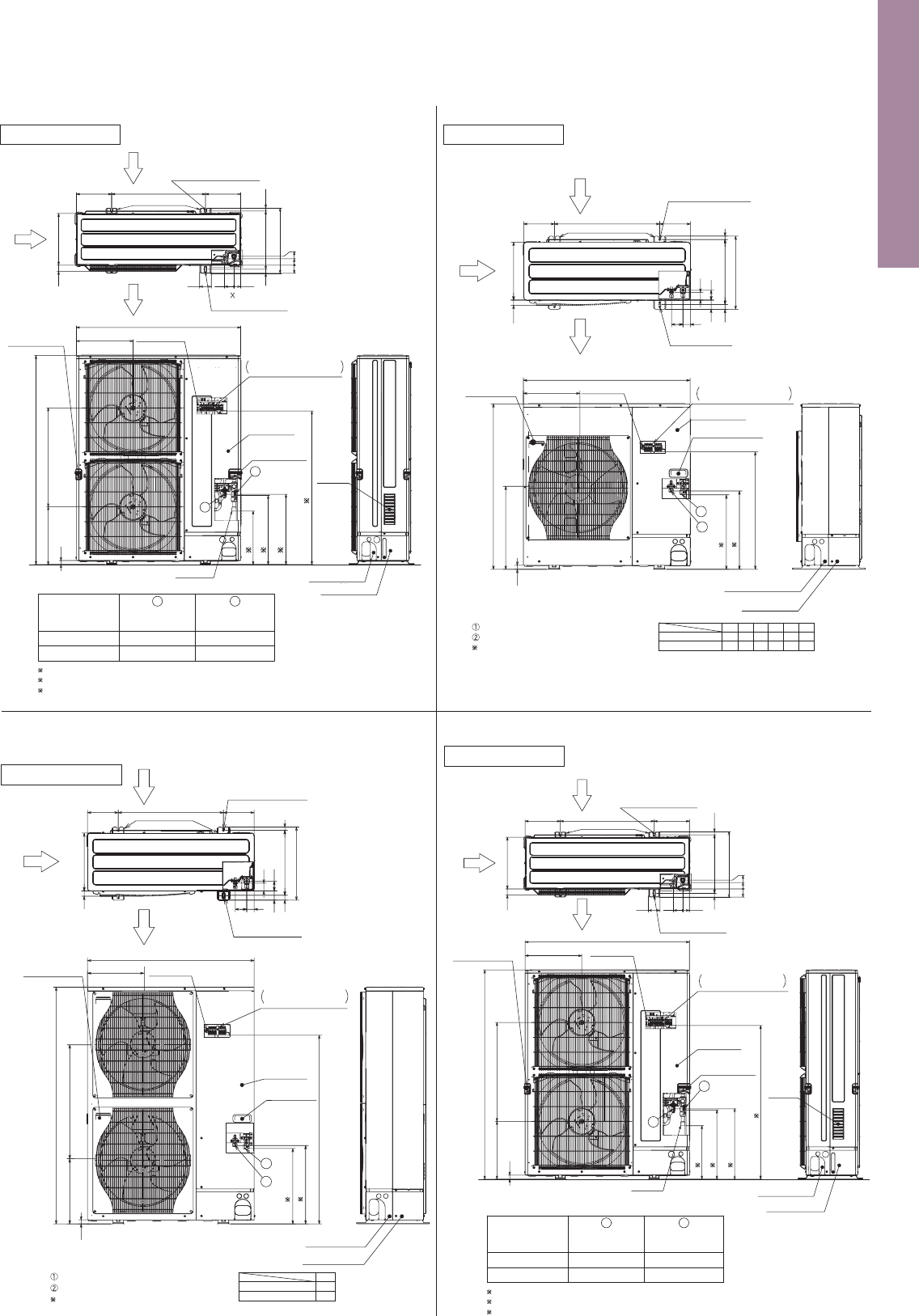
132
Unit : mm
PUHZ-ZRP35VKA PUHZ-ZRP50VKA
OUTDOOR UNIT
PUHZ-ZRP60VHA PUHZ-ZRP71VHA
OUTDOOR UNIT
322
950
473
943
23
447
431
673
2
1
Handle for moving
Handle for moving
Service panel
Earth terminal
Left:Power supply wiring
Right : Indoor / Outdoor wiring
Terminal connections
Rear piping cover
Front piping cover
40
54
28 370 19
417
53
57 41
600 175175
330
Rear air intake
Air discharge
Side air intake
Installation Feet
2 U-shaped notched holes
(Foundation Bolt M10)
2-12 36 oval holes
(foundation bolt M10)
30
PUHZ-SHW80VHA PUHZ-SHW112VHA
PUHZ-SHW112YHA PUHZ-SHW140YHA
OUTDOOR UNIT
...
Refrigerant gas pipe connection (flare)
...
Refrigerant liquid pipe connection (flare)
...
Indicates stop valve connection location.
PUHZ-ZRP100VKA2 PUHZ-ZRP125VKA2 PUHZ-ZRP140VKA2
PUHZ-ZRP100YKA2 PUHZ-ZRP125YKA2 PUHZ-ZRP140YKA2
OUTDOOR UNIT
Refrigerant GAS pipe
connection
2
...
Indication of STOP VALVE connection location.
1
...
Indication of Terminal connection location.
1
Refrigerant LIQUID pipe
connection
Handle for moving
Service panel
Air Intake
Front piping cover
...
Refrigerant gas pipe connection (flare)
...
Refrigerant liquid pipe connection (flare)
...
Indicates stop valve connection location.
Front piping cover
Rear piping cover
Air Discharge
Rear Air Intake
Side Air Intake
600175 175
330
417
42
66
53 56
45
(19)28 370
2-U Shaped notched holes
(Foundation Bolt M10)
2-12 x 36 Oval holes
(Foundation Bolt M10)
Installation Feet
30
23
SHW·VHA
SHW·YHA
1079
A
930
Handle for moving
Service panel
A
2
1
1 443
1 447
635
371
1350
322
950
Handle for moving
Handle
for
moving
Earth terminal
Terminal connection
Left ····Power supply wiring
Right··· Indoor/Outdoor wiring
Service port
Connection for
gas pipe
Connection for
liquid pipe
FLARE
6.35 (1/4F)
FLARE
12.7 (1/2F)
Service panel
for charge plug
Service panel
Earth terminal
( )
Terminal connection
Left
Power supply wiring
Right
Indoor/Outdoor wiring
Air discharge
Air intake
Air intake
oval hole
4-10×21
drain hole
42
360
330
32.5
300
40
404.5
48
Handle for moving
Installation bolt pitch
22.3
630
320
8.5
809
500
310
154.5
62
PUHZ-ZRP100~140VKA2.UK
PUHZ-ZRP100~140YK
A2.UK
PUHZ-ZRP100~140YK
A2.UK
Model
Model
450
450
C
442
442
B
919
1067
A
Rear Air Intake
Handle for moving
Installation feet
Air Discharge
Side Air Intake
2-U Shaped notched holes
(foundation bolt M10)
2-12×36 Oval holes
(foundation bolt M10)
225
362
1050
Earth terminal
75
56
40
0
53
4261
40 330
1338
369 632
26
(19)37028
417
225600
Terminal connection
Left
...
Power supply wiring
Right
..
Indoor/Outdoor wiring
1
2
Rear piping cover
B 2
A 1
C 2
2
ø15.88 (5/8F) ø9.52 (3/8F)
Unit : mm
PUHZ-ZRP200YKA PUHZ-ZRP250YKA
OUTDOOR UNIT
Rear Air Intake
Air Discharge
Side Air Intake
2-U shaped notched holes
(foundation bolt M10)
370
(19)
28
417
33040
225 225
600
75 61 42
40
53
56
0
1338
369
26
632
Handle for moving
PUHZ-P125VHA3 PUHZ-P140VHA3
PUHZ-P125YHAPUHZ-P140YHA
OUTDOOR UNIT
PUHZ-P100VHA4 PUHZ-P100YHA2
OUTDOOR UNIT
PUHZ-P200YKA PUHZ-P250YKA
OUTDOOR UNIT
417
C D
E
F
(19)37028
53
175600175
330
2-12 x 36 oval holes
(Foundation Bolt M10)
Air Discharge
Rear Air Intake
Side Air Intake
2-U Shaped notched holes
(Foundfation Bolt M10)
Installation Feet
30
···Refrigerant GAS pipe connection (FLARE)
···Refrigerant LIQUID pipe connection (FLARE)
1 ···Indication of STOP VALVE connection location.
Front piping cover
Rear piping cover
23
943
473
950
322
1 447
1 A
B
Terminal Connections
Left···Power supply wiring
Right···Indoor/Outdoor wiring
Earth terminal
Service panel
Handle for moving
Handle for moving
1
2
F
56
54
E
45
41
D
42
41
C
66
56
B
670
589
PUHZ-P100VHA4
PUHZ-P100YHA2
A
443
431
Front piping cover
Rear piping cover
Terminal connection
Left···Power supply wiring
Right···Indoor/Outdoor wiring
Earth terminal
Service panel
Handle for moving
1
2
Air Discharge
Rear Air Intake
Side Air Intake
···Refrigerant GAS pipe connection (FLARE)
···Refrigerant LIQUID pipe connection (FLARE)
···Indication of STOP VALVE connection location.
600
225 225
75 61 42
(19)
370
330
1338
632369
26
40
417
28
600
1050
362
175 175
330
417
41
56
53 54
41
(19)28 370
2-U Shaped notched holes
(Foundation Bolt M10)
2-12 x 36 Oval holes
(Foundation Bolt M10)
Installation Feet
30
1350
23
950
A
1 447
1 431
371 635
322
Handle for moving
PUHZ-P125/140VHA3
PUHZ-P125/140YHA
A
1076
994
1
Earth terminal
Service panel
Handle for moving
Air Discharge
Rear Air Intake
Side Air Intake
2-U Shaped notched holes
(foundation Bolt M10)
2-12 x 36 Oval holes
(foundation Bolt M10)
Installation Feet
Handle for moving
2 342
3 442
3 450
1 985
2
...
Refrigerant GAS pipe connection (BRAZING) O.Dø25.4.
3
...
Indication of STOP VALVE connection location.
1
...
Indication of Terminal connection location.
Refrigerant GAS pipe
connection
1
Refrigerant LIQUID pipe
connection
PUHZ-P250YKA.UK
Model
2
ø19.05 (3/4F) ø12.7 (1/2F)
PUHZ-P200YKA.UK
ø19.05 (3/4F) ø9.52 (3/8F)
Installation Feet
2-12 36 Oval holes
(foundation bolt M10)
1050
Earth terminal
362
Terminal connection
Left
...
Power supply wiring
Right
...
Indoor/Outdoor wiring
Handle for moving
BRAZING
Service panel
Air Intake
Front piping cover
Rear piping cover
2
...
Refrigerant GAS pipe connection (BRAZING) O.Dø25.4.
3
...
Indication of STOP VALVE connection location.
1
...
Indication of Terminal connection location.
2 342
3 442
3 450
1 985
1
2
Refrigerant GAS pipe
connection
1
Refrigerant LIQUID pipe
connection
PUHZ-ZRP250YKA.UK
Model
2
ø19.05 (3/4F) ø12.7 (1/2F)
PUHZ-ZRP200YKA.UK
ø19.05 (3/4F) ø9.52 (3/8F)
40
53
56
0
Terminal connection
Left···Power supply wiring
Right···Indoor/Outdoor wiring
1
2
Front piping cover
Air Intake
BRAZING
Rear piping cover
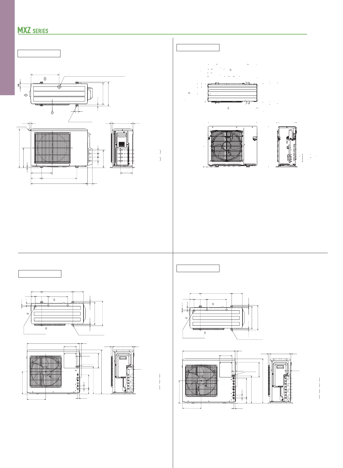
133
Unit : mm
MXZ-6D122VA
OUTDOOR UNIT
MXZ-4E83VA MXZ-5E102VA
OUTDOOR UNIT
MXZ-4E83VAHZ
OUTDOOR UNIT
Side Air Intake
33 Drain Hole6-
(Foundation Bolt M10)
2-12 x 36 Oval Hole
Air
Discharge
(Bolt Pitch)
417
370
10
10
40
62134
51
1631
2-U Shaped Notched Hole
(Foundation Bolt M10)
Rear Air
Intake
600175
10
10
250 11680 97
71
51
10
175
Handle
Handle
950
361
563
1048
Unit A
Unit B
Unit C
Unit D
Air Intake
Handle
LIQ 6.35(1/4")FLARE
GAS 12.7(1/2")FLARE
LIQ 6.35(1/4")FLARE
GAS 9.52(3/8")FLARE
LIQ
GAS
LIQ
GAS
GAS
LIQ
LIQ
GAS
70
25 15330
Handle
Air Intake
Handle
330
70
25 15
6-ø33 Drain Hole
Air in
Air out
Air in
(Foundation Bolt M10)
2-U Shaped Notched Hole
(Foundation Bolt M10)
2-12×36 Oval Hole
(Bolt pitch)
1169705208
51
71
134
40
62
10
10
10
10
175600 175
10
10
417
31 16370
36
51
Handle
Handle
361
563
1048
950
Liquid pipe : Ø6.35(flared)1/4
E unit
connection
D unit
connection
C unit
connection
B unit
connection
A unit
connection
F unit
connection
Gas pipe : Ø9.52(flared)3/8
Liquid pipe : Ø6.35(flared)1/4
Gas pipe : Ø9.52(flared)3/8
Liquid pipe : Ø6.35(flared)1/4
Gas pipe : Ø9.52(flared)3/8
Liquid pipe : Ø6.35(flared)1/4
Gas pipe : Ø9.52(flared)3/8
Liquid pipe : Ø6.35(flared)1/4
Gas pipe : Ø9.52(flared)3/8
Liquid pipe : Ø6.35(flared)1/4
Gas pipe : Ø12.7(flared)1/2
Unit : mm
MXZ-2D33VA MXZ-2D42VA(2) MXZ-2D53VA(2)
MXZ-2D53VAH MXZ-2DM40VA
OUTDOOR UNIT
Liquid pipe : ø6.35(flared)1/4
C unit
connection
B unit
connection
A unit
connection
Gas pipe : ø9.52(flared)3/8
Liquid pipe : ø6.35(flared)1/4
Gas pipe : ø9.52(flared)3/8
Liquid pipe : ø6.35(flared)1/4
Gas pipe : ø9.52(flared)3/8
Liquid pipe : Ø6.35(flared)1/4
D unit
connection
C unit
connection
B unit
connection
A unit
connection
Gas pipe : Ø9.52(flared)3/8
Liquid pipe : Ø6.35(flared)1/4
Gas pipe : Ø9.52(flared)3/8
Liquid pipe : Ø6.35(flared)1/4
Gas pipe : Ø9.52(flared)3/8
Liquid pipe : Ø6.35(flared)1/4
Gas pipe : Ø12.7(flared)1/2
25.8
30840
171500
500150
302.5
10
280
550
22.3
400
40
2-10×21 Oval hole
17.5
304~325
344.5
Drain hole ø42 (In case of Base heater models ø33)
Air in
Air in
Air out
18 13285
170.4
B unit
connection
A unit
connection
Handle
800 69
251.1
51 51 51
Air in
Air out
Drain hole 3-ø33
207.5 31465.4
169
200
27.1
23.1
299
710
240
17.7
12.3
360.6
18.3 17.7
16.6
34
440
360
31584
45
330 13
66.3
Connecting
Wire Hole
(39×27)
4-10×21 Oval hole
(Foundation bolt M8)
(Bolt Pitch)
396
Liquid pipe: ø6.35 (flared) 1/4
Gas pipe : ø9.52 (flared) 3/8
Liquid pipe: ø6.35 (flared) 1/4
Gas pipe : ø9.52 (flared) 3/8
299
840
200
30
25.8 330 13
66.3
360
23.1
27.1
240
710
440
22584
45
Connecting
Wire Hole
(39×27)
Drain hole 3-ø33
Air in
Air in
Air out
169
65.4 207.5 314
500 171
4-10×21 Oval hole
(Foundation bolt M8)
(Bolt Pitch)
396
360.6
17.7 17.718.3
16.6
34
12.3
MXZ-3E54VA MXZ-3E68VA
MXZ-3DM50VA
OUTDOOR UNIT
MXZ-4E72VA
OUTDOOR UNIT
MXZ-2E53VAHZ
OUTDOOR UNIT
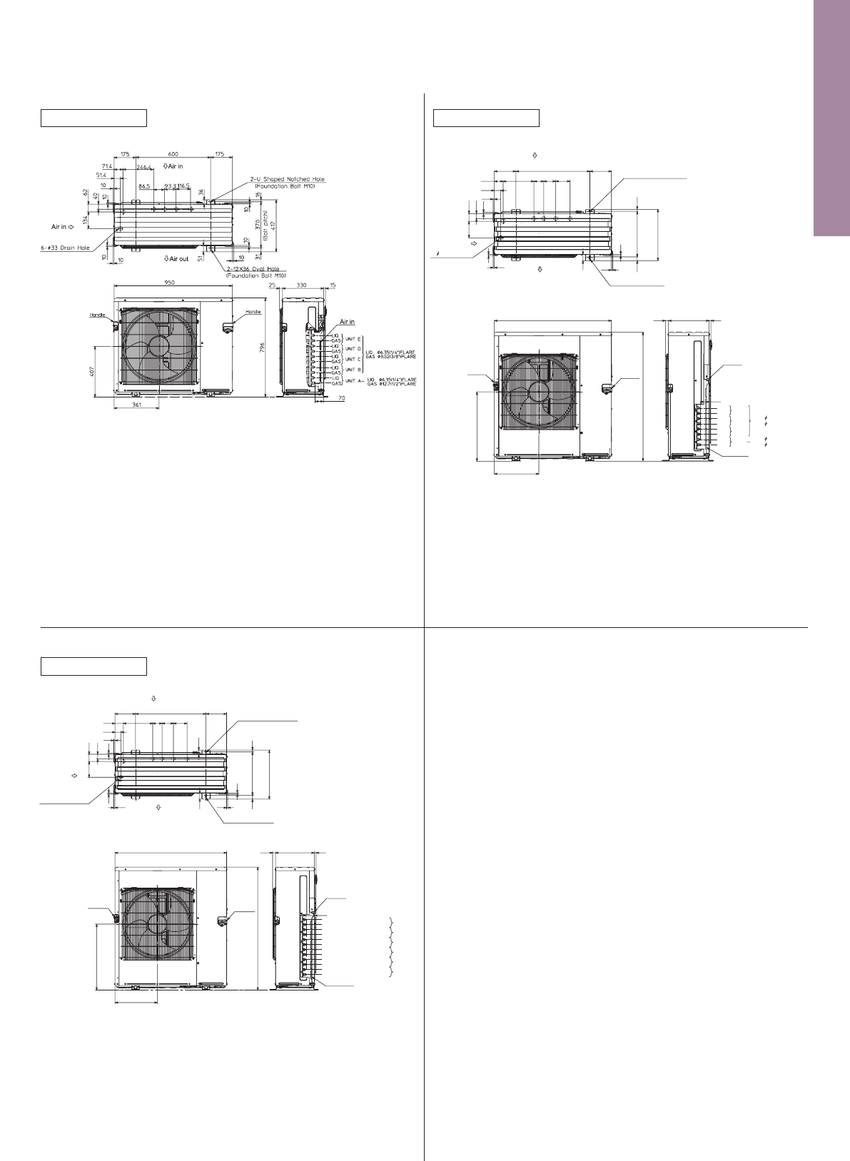
134
Unit : mm
MXZ-6D122VA
OUTDOOR UNIT
MXZ-4E83VA MXZ-5E102VA
OUTDOOR UNIT
MXZ-4E83VAHZ
OUTDOOR UNIT
Side Air Intake
33 Drain Hole6-
(Foundation Bolt M10)
2-12 x 36 Oval Hole
Air
Discharge
(Bolt Pitch)
417
370
10
10
40
62134
51
1631
2-U Shaped Notched Hole
(Foundation Bolt M10)
Rear Air
Intake
600175
10
10
250 11680 97
71
51
10
175
Handle
Handle
950
361
563
1048
Unit A
Unit B
Unit C
Unit D
Air Intake
Handle
LIQ 6.35(1/4")FLARE
GAS 12.7(1/2")FLARE
LIQ 6.35(1/4")FLARE
GAS 9.52(3/8")FLARE
LIQ
GAS
LIQ
GAS
GAS
LIQ
LIQ
GAS
70
25 15330
Handle
Air Intake
Handle
330
70
25 15
6-ø33 Drain Hole
Air in
Air out
Air in
(Foundation Bolt M10)
2-U Shaped Notched Hole
(Foundation Bolt M10)
2-12×36 Oval Hole
(Bolt pitch)
1169705208
51
71
134
40
62
10
10
10
10
175600 175
10
10
417
31 16370
36
51
Handle
Handle
361
563
1048
950
Liquid pipe : Ø6.35(flared)1/4
E unit
connection
D unit
connection
C unit
connection
B unit
connection
A unit
connection
F unit
connection
Gas pipe : Ø9.52(flared)3/8
Liquid pipe : Ø6.35(flared)1/4
Gas pipe : Ø9.52(flared)3/8
Liquid pipe : Ø6.35(flared)1/4
Gas pipe : Ø9.52(flared)3/8
Liquid pipe : Ø6.35(flared)1/4
Gas pipe : Ø9.52(flared)3/8
Liquid pipe : Ø6.35(flared)1/4
Gas pipe : Ø9.52(flared)3/8
Liquid pipe : Ø6.35(flared)1/4
Gas pipe : Ø12.7(flared)1/2
Unit : mm
MXZ-2D33VA MXZ-2D42VA(2) MXZ-2D53VA(2)
MXZ-2D53VAH MXZ-2DM40VA
OUTDOOR UNIT
Liquid pipe : ø6.35(flared)1/4
C unit
connection
B unit
connection
A unit
connection
Gas pipe : ø9.52(flared)3/8
Liquid pipe : ø6.35(flared)1/4
Gas pipe : ø9.52(flared)3/8
Liquid pipe : ø6.35(flared)1/4
Gas pipe : ø9.52(flared)3/8
Liquid pipe : Ø6.35(flared)1/4
D unit
connection
C unit
connection
B unit
connection
A unit
connection
Gas pipe : Ø9.52(flared)3/8
Liquid pipe : Ø6.35(flared)1/4
Gas pipe : Ø9.52(flared)3/8
Liquid pipe : Ø6.35(flared)1/4
Gas pipe : Ø9.52(flared)3/8
Liquid pipe : Ø6.35(flared)1/4
Gas pipe : Ø12.7(flared)1/2
25.8
30840
171500
500150
302.5
10
280
550
22.3
400
40
2-10×21 Oval hole
17.5
304~325
344.5
Drain hole ø42 (In case of Base heater models ø33)
Air in
Air in
Air out
18 13285
170.4
B unit
connection
A unit
connection
Handle
800 69
251.1
51 51 51
Air in
Air out
Drain hole 3-ø33
207.5 31465.4
169
200
27.1
23.1
299
710
240
17.7
12.3
360.6
18.3 17.7
16.6
34
440
360
31584
45
330 13
66.3
Connecting
Wire Hole
(39×27)
4-10×21 Oval hole
(Foundation bolt M8)
(Bolt Pitch)
396
Liquid pipe: ø6.35 (flared) 1/4
Gas pipe : ø9.52 (flared) 3/8
Liquid pipe: ø6.35 (flared) 1/4
Gas pipe : ø9.52 (flared) 3/8
299
840
200
30
25.8 330 13
66.3
360
23.1
27.1
240
710
440
22584
45
Connecting
Wire Hole
(39×27)
Drain hole 3-ø33
Air in
Air in
Air out
169
65.4 207.5 314
500 171
4-10×21 Oval hole
(Foundation bolt M8)
(Bolt Pitch)
396
360.6
17.7 17.718.3
16.6
34
12.3
MXZ-3E54VA MXZ-3E68VA
MXZ-3DM50VA
OUTDOOR UNIT
MXZ-4E72VA
OUTDOOR UNIT
MXZ-2E53VAHZ
OUTDOOR UNIT
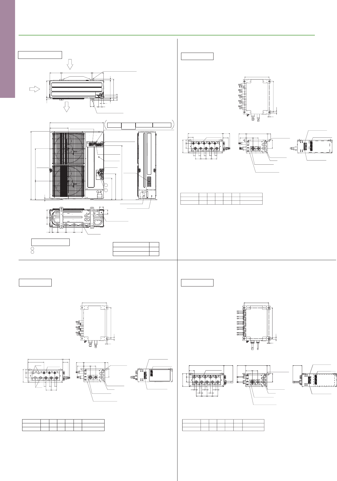
135
Unit : mm
PUMY-P112/125/140VKM2
PUMY-P112/125/140YKM2
OUTDOOR UNIT
PUMY SERIES
Suspension bolt: W3/W8 (M10)
PAC-MK51BC
Branch box
Suspension bolt: W3/W8 (M10)
PAC-MK51BCB
Branch box
Suspension bolt: W3/W8 (M10)
PAC-MK31BC
Branch box
Air Intake
Front piping cover
Rear piping cover
Installation Feet
2-U Shaped notched holes
(Foundation Bolt M10)
2-12×36 Oval holes
(Foundation Bolt M10)
Side Air Intake
Rear Air Intake
Air Discharge
70
42
56
417
225
25 330
600 225
28 19370
53
56
33
0
1
2
From left to right
For concentration
control
For the
transmission line
For the
branch box
power supply
Te rminal connection
For the
power supply
Ground for
the branch box
power supply
Handle for
moving
Handle for
moving
Ground for the transmission line
Ground for concentration control
Ground for the power supply
("GR"marking position)
Service panel
362
1050
26
1338
*1 426
*1 510
A
369 632
Drain hole
Model A
PUMY-P112/125/140VKM21062
PUMY-P112/125/140YKM2909
(5-ø33)
Bottom piping hole
(Knock-Out)
86
81
45 160160160110
154136
•••
Indication of STOP VALVE connection location.
1
2
•••
Refrigerant GAS pipe connection (FLARE) ø15.88 (5/8F)
•••
Refrigerant LIQUID pipe connection (FLARE) ø9.52 (3/8F)
Example of Notes
*1
Suspension bolt pitch
Suspension bolt pitch
402
24
12
320
Suspension bolt pitch
320
To indoor unit
170
4765
25 25 25
25 25
70 70
72
67
450 90
70
70
To outdoor unit
Service panel
(for lev. thermistor)
Control cover
Bush
5-electric wire
inlet
87 70
112
96
83
280 40
TB3BTB3D
TB3ATB3C TB3E
TB5
TB2B
Terminal block
to outdoor unit
Terminal block
to indoor unit
Terminal block
to M-net unit
Suspension bolt : W3/8(M10)
Gas pipe
Refrigerant pipe flared connection
1/4F 1/4F 1/4F 1/4F 1/4F 3/8F
3/8F
3/8F
3/8F 3/8F 1/2F 5/8F
To outdoor unit
Liquid pipe
ABCD E
E
E
D
D
C
C
B
B
A
A
ABC
Liquid pipe
To outdoor unit
5/8F3/8F
3/8F
3/8F
3/8F1/4F1/4F1/4F
Refrigerant pipe flared connection
Gas pipe
Suspension bolt : W3/8(M10)
To indoor
unit
A
A
B
C
C
B
Cap
Cap
72
90
25 25
209
170
47
65
25
70
70
450
112
7087
280
40
96
83
TB2B
TB5
TB3B
TB3CTB3A
Suspension bolt pitch
402
24
12
Service panel
(for lev. thermistor)
To outdoor unit
Bush
Control cover
5-electric wire
inlet
Terminal block
to M-net unit
Terminal block
to indoor unit
Terminal block
to outdoor unit
Suspension bolt pitch
402
24
12
119
Suspension bolt pitch
320
5-electric wire
inlet
112
Terminal block
to outdoor unit
Terminal block
to indoor unit
Terminal block
to M-net unit
Suspension bolt : W3/8(M10)
Gas pipe
Refrigerant pipe brazed connection
ø6.35
ø9.52
ø6.35
ø9.52
ø6.35
ø9.52
ø6.35
ø9.52
ø6.35
ø12.7
ø9.52
ø15.88
To outdoor unit
Liquid pipe
ABCD E
E
E
D
D
C
C
B
B
A
A
TB3B TB3D
TB3A TB3C TB3E
TB5
TB2B
87 70
113119450280
67
65 47
170
40
To outdoor unit
Service panel
(for lev. thermistor)
Control cover
Bush
To indoor unit
70707070
25
25 25
25 25
Unit : mm
Suspension bolt: W3/W8 (M10)
PAC-MK31BCB
Branch box
Suspension bolt : W3/8(M10)
Gas pipe
Refrigerant pipe brazed connection
ø6.35
ø9.52
ø6.35
ø9.52
ø6.35
ø9.52
ø9.52
ø15.88
To outdoor unit
Liquid pipe
ABC
Suspension bolt pitch
402
24
12
Suspension bolt pitch
320
5-electric wire
inlet
112
65 47
170
87 70
113280 40
To outdoor unit
Service panel
(for lev. thermistor)
Control cover
Bush
119450
209
CAP
CAP
To indoor unit
70
25 25
25
70
TB3B
TB3A TB3C
TB5
TB2B
A
A
B
BC
C
Terminal block
to outdoor unit
Terminal block
to indoor unit
Terminal block
to M-net unit
119
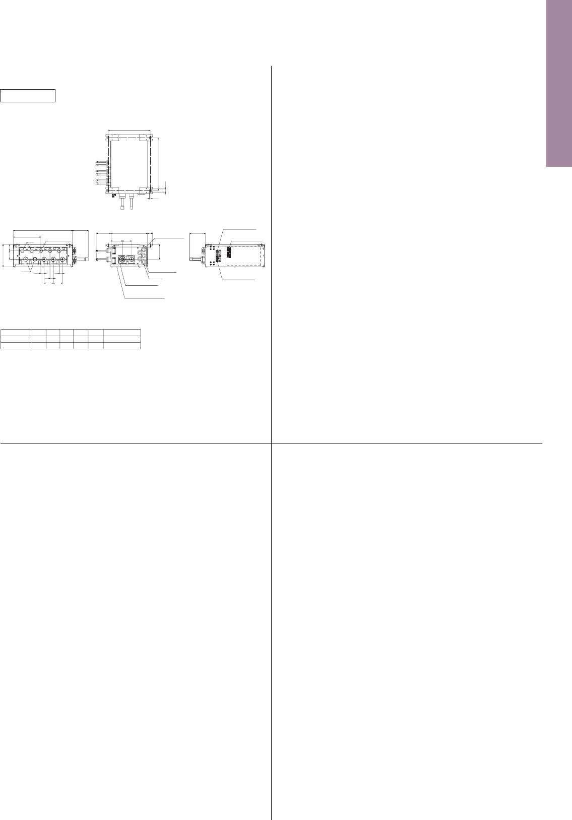
136
Unit : mm
PUMY-P112/125/140VKM2
PUMY-P112/125/140YKM2
OUTDOOR UNIT
PUMY SERIES
Suspension bolt: W3/W8 (M10)
PAC-MK51BC
Branch box
Suspension bolt: W3/W8 (M10)
PAC-MK51BCB
Branch box
Suspension bolt: W3/W8 (M10)
PAC-MK31BC
Branch box
Air Intake
Front piping cover
Rear piping cover
Installation Feet
2-U Shaped notched holes
(Foundation Bolt M10)
2-12×36 Oval holes
(Foundation Bolt M10)
Side Air Intake
Rear Air Intake
Air Discharge
70
42
56
417
225
25 330
600 225
28 19370
53
56
33
0
1
2
From left to right
For concentration
control
For the
transmission line
For the
branch box
power supply
Te rminal connection
For the
power supply
Ground for
the branch box
power supply
Handle for
moving
Handle for
moving
Ground for the transmission line
Ground for concentration control
Ground for the power supply
("GR"marking position)
Service panel
362
1050
26
1338
*1 426
*1 510
A
369 632
Drain hole
Model A
PUMY-P112/125/140VKM21062
PUMY-P112/125/140YKM2909
(5-ø33)
Bottom piping hole
(Knock-Out)
86
81
45 160160160110
154136
•••
Indication of STOP VALVE connection location.
1
2
•••
Refrigerant GAS pipe connection (FLARE) ø15.88 (5/8F)
•••
Refrigerant LIQUID pipe connection (FLARE) ø9.52 (3/8F)
Example of Notes
*1
Suspension bolt pitch
Suspension bolt pitch
402
24
12
320
Suspension bolt pitch
320
To indoor unit
170
4765
25 25 25
25 25
70 70
72
67
450 90
70
70
To outdoor unit
Service panel
(for lev. thermistor)
Control cover
Bush
5-electric wire
inlet
87 70
112
96
83
280 40
TB3BTB3D
TB3ATB3C TB3E
TB5
TB2B
Terminal block
to outdoor unit
Terminal block
to indoor unit
Terminal block
to M-net unit
Suspension bolt : W3/8(M10)
Gas pipe
Refrigerant pipe flared connection
1/4F 1/4F 1/4F 1/4F 1/4F 3/8F
3/8F
3/8F
3/8F 3/8F 1/2F 5/8F
To outdoor unit
Liquid pipe
ABCD E
E
E
D
D
C
C
B
B
A
A
ABC
Liquid pipe
To outdoor unit
5/8F3/8F
3/8F
3/8F
3/8F1/4F1/4F1/4F
Refrigerant pipe flared connection
Gas pipe
Suspension bolt : W3/8(M10)
To indoor
unit
A
A
B
C
C
B
Cap
Cap
72
90
25 25
209
170
47
65
25
70
70
450
112
7087
280
40
96
83
TB2B
TB5
TB3B
TB3CTB3A
Suspension bolt pitch
402
24
12
Service panel
(for lev. thermistor)
To outdoor unit
Bush
Control cover
5-electric wire
inlet
Terminal block
to M-net unit
Terminal block
to indoor unit
Terminal block
to outdoor unit
Suspension bolt pitch
402
24
12
119
Suspension bolt pitch
320
5-electric wire
inlet
112
Terminal block
to outdoor unit
Terminal block
to indoor unit
Terminal block
to M-net unit
Suspension bolt : W3/8(M10)
Gas pipe
Refrigerant pipe brazed connection
ø6.35
ø9.52
ø6.35
ø9.52
ø6.35
ø9.52
ø6.35
ø9.52
ø6.35
ø12.7
ø9.52
ø15.88
To outdoor unit
Liquid pipe
ABCD E
E
E
D
D
C
C
B
B
A
A
TB3B TB3D
TB3A TB3C TB3E
TB5
TB2B
87 70
113119450280
67
65 47
170
40
To outdoor unit
Service panel
(for lev. thermistor)
Control cover
Bush
To indoor unit
70707070
25
25 25
25 25
Unit : mm
Suspension bolt: W3/W8 (M10)
PAC-MK31BCB
Branch box
Suspension bolt : W3/8(M10)
Gas pipe
Refrigerant pipe brazed connection
ø6.35
ø9.52
ø6.35
ø9.52
ø6.35
ø9.52
ø9.52
ø15.88
To outdoor unit
Liquid pipe
ABC
Suspension bolt pitch
402
24
12
Suspension bolt pitch
320
5-electric wire
inlet
112
65 47
170
87 70
113280 40
To outdoor unit
Service panel
(for lev. thermistor)
Control cover
Bush
119450
209
CAP
CAP
To indoor unit
70
25 25
25
70
TB3B
TB3A TB3C
TB5
TB2B
A
A
B
BC
C
Terminal block
to outdoor unit
Terminal block
to indoor unit
Terminal block
to M-net unit
119
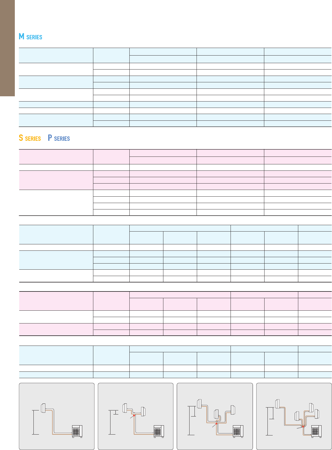
137
Single type Twin type
H
h
B
C
A
Total length A+B+C
Distribution
pipe
Triple type
Total length A+B+C+D
Quadruple type
H
h
A
D
E
Total length A+B+C+D+E
H
h
Farthest & Highest
Farthest & Highest
Closest
& Lowest
Closest
& Lowest
A
D
Distribution
pipe
Distribution
pipe
H
A
C
C
B
B
MSZ-F
MFZ-KJ
MSZ-E
MSZ-S
ZUBADAN (PUHZ-SHW)
POWER INVERTER (PUHZ-ZRP)
STANDARD INVERTER
(PUHZ-P & SUZ)
Single type
Series
Series
Series
ZUBADAN (PUHZ-SHW)
POWER INVERTER (PUHZ-ZRP)
STANDARD INVERTER (PUHZ-P)
Twin type
Triple type
Quadruple type
1
1
1
1
1
1
15
15
15
15
15
15
15
15
15
15
15
15
POWER INVERTER (PUHZ-ZRP)
STANDARD INVERTER (PUHZ-P)
POWER INVERTER (PUHZ-ZRP)
STANDARD INVERTER (PUHZ-P)
25 / 35
50
25 / 35 / 42
50
60 / 71
80 / 112 / 140
35 / 50 / 60 / 71
100 / 125 / 140
200 / 250
25 / 35
50 / 60 / 71
100 / 125 / 140
200 / 250
20
30
20
30
30
12
15
12
15
15
10
10
25 / 35 / 42 20
12
10
50 30
15
10
10
10
10
MSZ-H 25 / 35 / 50 20
12
10
MSZ-G 60 / 71 30
15
10
Series
75
50
75
100
20
30
50
70
30
30
30
30
12
30
30
30
15
15
15
15
10
10
15
15
Class
<
Outdoor unit
>
80 / 112 / 140
71
100 / 125 / 140
200 / 250
100 / 125 / 140
200 / 250
200 / 250
200 / 250
140
140
200 / 250
200 / 250
1
1
1
1
1
1
20
20
20
30
20
30
8
8
8
8
8
8
30
30
30
30
30
30
30
30
30
30
30
30
75
50
75
100
50
70
75
100
50
70
100
70
20
30
20
28
30
22
8
8
8
8
8
8
Maximum Piping Length (m)
Maximum Height Difference (m)
Indoor unit -
Indoor unit
h
Indoor unit -
Distribution pipe
B
Outdoor unit -
Indoor unit
H
Total length
A+B+C
Pipe length difference
from distribution pipe
|
B-C
|
Maximum Piping Length (m)
Total length (A)
Maximum Height Difference (m)
Outdoor unit - Indoor unit (H)
Maximum Number of Bends
Total number
Class
<
Outdoor unit
>
Class
<
Outdoor unit
>
Maximum Piping Length (m)
Total length (A)
Maximum Height Difference (m)
Outdoor unit - Indoor unit (H)
Maximum Number of Bends
Total number
Series
Maximum Number of Bends
Total number
Indoor unit -
Distribution pipe
B
Total length
A+B+C+D
Pipe length difference
from distribution pipe
|
B-C
|
Indoor unit -
Distribution pipe
B
Total length
A+B+C+D+E
Pipe length difference
from distribution pipe
|
B-C
|
Piping Installation
Single type
Class
<
Outdoor unit
>
Maximum Piping Length (m)
Maximum Height Difference (m)
Indoor unit -
Indoor unit
h
Outdoor unit -
Indoor unit
H
Maximum Number of Bends
Total number
Class
<
Outdoor unit
>
Maximum Piping Length (m)
Maximum Height Difference (m)
Indoor unit -
Indoor unit
h
Outdoor unit -
Indoor unit
H
Maximum Number of Bends
Total number
&
MSZ-D 25 / 35 20
12
10
20m
30m
20
30
Outdoor unit - Indoor unit (a,b) 15m
Total length (a+b) 20m
Outdoor unit - Indoor unit (a,b) 15
20Total number (a+b)
Outdoor unit - Indoor unit (a,b)
Total length (a+b)
Outdoor unit - Indoor unit (a,b)
Total number (a+b)
Outdoor unit - Indoor unit (a,b)
Total length (a+b)
Outdoor unit - Indoor unit (a,b)
Total number (a+b)
Outdoor unit - Indoor unit (a,b,c)
Total length (a+b+c)
Outdoor unit - Indoor unit (a,b,c)
Total number (a+b+c)
Maximum Piping Length
Maximum Number of Bends
Maximum Piping Length
Maximum Number of Bends
Maximum Piping Length
Maximum Number of Bends
Maximum Piping Length
Maximum Number of Bends
Outdoor unit - Indoor unit (a,b,c)
Total length (a+b+c)
Outdoor unit - Indoor unit (a,b,c)
Total number (a+b+c)
Maximum Piping Length
Maximum Number of Bends
MXZ-2D33VA
* When connecting MFZ-KJ Series indoor unit, additional refrigerant is required. For details, please contact Mitsubishi Electric.
Regarding MXZ-2D33, the second unit should be a dierent type in the case of selecting one MFZ-KJ.
* When connecting MFZ-KJ Series indoor unit to MXZ-2D42VA or MXZ-2D53VA(H), additional refrigerant is required.
For details, please contact Mitsubishi Electric.
* When connecting MFZ-KJ Series indoor unit, additional refrigerant is required. For details, please contact
Mitsubishi Electric.
a
b
Outdoor
unit
Maximum height
difference
Indoor
units
Outdoor unit
|
Indoor unit
10m
Outdoor unit
|
Indoor unit
10m
Indoor unit
|
Indoor unit
10m
25m
50m
25
50
MXZ-3E54VA
25m
60m
25
60
MXZ-3E68VA
20m
30m
20
30
MXZ-2D53VA(2)
(
H
),
MXZ-2E53VA
HZ
a
b
c
Outdoor
unit
Indoor
units
a
b
Outdoor
unit
Indoor
units
*Outdoor unit
installed lower
*Outdoor unit
installed higher
Outdoor unit
|
Indoor unit
15m
Outdoor unit
|
Indoor unit
10m
Indoor unit
|
Indoor unit
15m
*Outdoor unit
installed lower
*Outdoor unit
installed higher
Outdoor unit
|
Indoor unit
15m
Outdoor unit
|
Indoor unit
10m
Indoor unit
|
Indoor unit
15m
*Outdoor unit
installed lower
*Outdoor unit
installed higher
Maximum height
difference
Maximum height
difference
MXZ-2D42VA(2)
Highest
Lowest
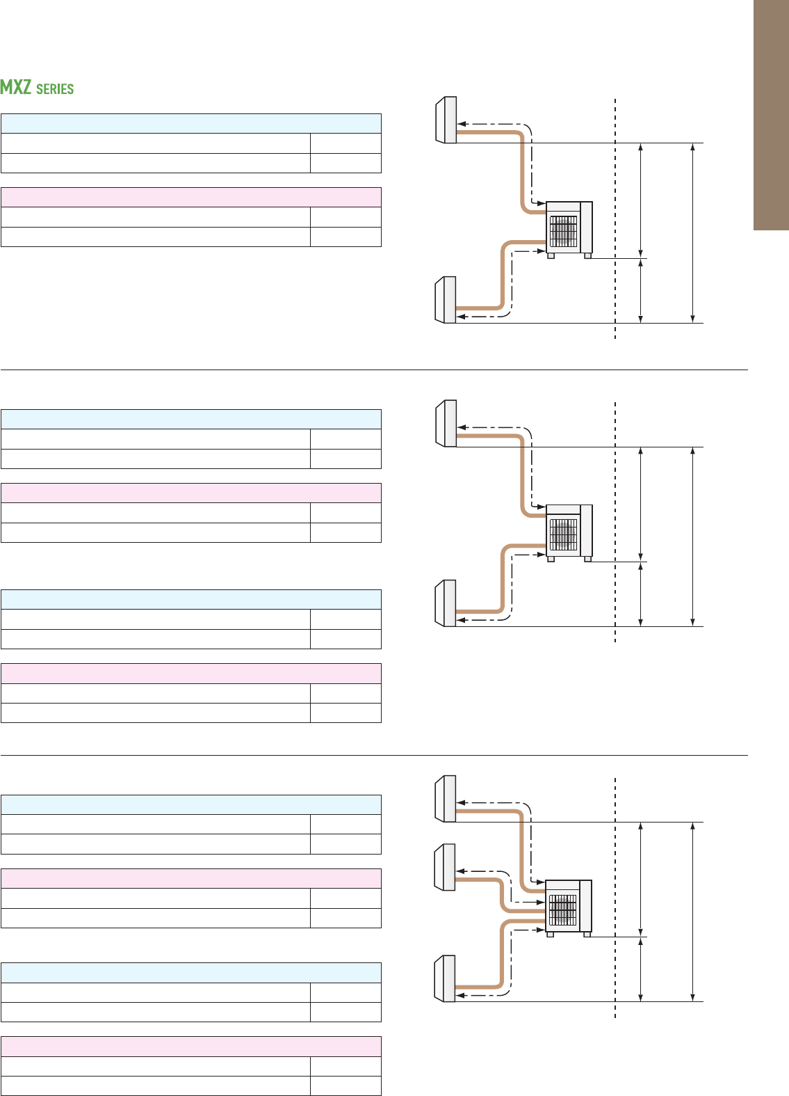
138
Single type Twin type
H
h
B
C
A
Total length A+B+C
Distribution
pipe
Triple type
Total length A+B+C+D
Quadruple type
H
h
A
D
E
Total length A+B+C+D+E
H
h
Farthest & Highest
Farthest & Highest
Closest
& Lowest
Closest
& Lowest
A
D
Distribution
pipe
Distribution
pipe
H
A
C
C
B
B
MSZ-F
MFZ-KJ
MSZ-E
MSZ-S
ZUBADAN (PUHZ-SHW)
POWER INVERTER (PUHZ-ZRP)
STANDARD INVERTER
(PUHZ-P & SUZ)
Single type
Series
Series
Series
ZUBADAN (PUHZ-SHW)
POWER INVERTER (PUHZ-ZRP)
STANDARD INVERTER (PUHZ-P)
Twin type
Triple type
Quadruple type
1
1
1
1
1
1
15
15
15
15
15
15
15
15
15
15
15
15
POWER INVERTER (PUHZ-ZRP)
STANDARD INVERTER (PUHZ-P)
POWER INVERTER (PUHZ-ZRP)
STANDARD INVERTER (PUHZ-P)
25 / 35
50
25 / 35 / 42
50
60 / 71
80 / 112 / 140
35 / 50 / 60 / 71
100 / 125 / 140
200 / 250
25 / 35
50 / 60 / 71
100 / 125 / 140
200 / 250
20
30
20
30
30
12
15
12
15
15
10
10
25 / 35 / 42 20
12
10
50 30
15
10
10
10
10
MSZ-H 25 / 35 / 50 20
12
10
MSZ-G 60 / 71 30
15
10
Series
75
50
75
100
20
30
50
70
30
30
30
30
12
30
30
30
15
15
15
15
10
10
15
15
Class
<
Outdoor unit
>
80 / 112 / 140
71
100 / 125 / 140
200 / 250
100 / 125 / 140
200 / 250
200 / 250
200 / 250
140
140
200 / 250
200 / 250
1
1
1
1
1
1
20
20
20
30
20
30
8
8
8
8
8
8
30
30
30
30
30
30
30
30
30
30
30
30
75
50
75
100
50
70
75
100
50
70
100
70
20
30
20
28
30
22
8
8
8
8
8
8
Maximum Piping Length (m)
Maximum Height Difference (m)
Indoor unit -
Indoor unit
h
Indoor unit -
Distribution pipe
B
Outdoor unit -
Indoor unit
H
Total length
A+B+C
Pipe length difference
from distribution pipe
|
B-C
|
Maximum Piping Length (m)
Total length (A)
Maximum Height Difference (m)
Outdoor unit - Indoor unit (H)
Maximum Number of Bends
Total number
Class
<
Outdoor unit
>
Class
<
Outdoor unit
>
Maximum Piping Length (m)
Total length (A)
Maximum Height Difference (m)
Outdoor unit - Indoor unit (H)
Maximum Number of Bends
Total number
Series
Maximum Number of Bends
Total number
Indoor unit -
Distribution pipe
B
Total length
A+B+C+D
Pipe length difference
from distribution pipe
|
B-C
|
Indoor unit -
Distribution pipe
B
Total length
A+B+C+D+E
Pipe length difference
from distribution pipe
|
B-C
|
Piping Installation
Single type
Class
<
Outdoor unit
>
Maximum Piping Length (m)
Maximum Height Difference (m)
Indoor unit -
Indoor unit
h
Outdoor unit -
Indoor unit
H
Maximum Number of Bends
Total number
Class
<
Outdoor unit
>
Maximum Piping Length (m)
Maximum Height Difference (m)
Indoor unit -
Indoor unit
h
Outdoor unit -
Indoor unit
H
Maximum Number of Bends
Total number
&
MSZ-D 25 / 35 20
12
10
20m
30m
20
30
Outdoor unit - Indoor unit (a,b) 15m
Total length (a+b) 20m
Outdoor unit - Indoor unit (a,b) 15
20Total number (a+b)
Outdoor unit - Indoor unit (a,b)
Total length (a+b)
Outdoor unit - Indoor unit (a,b)
Total number (a+b)
Outdoor unit - Indoor unit (a,b)
Total length (a+b)
Outdoor unit - Indoor unit (a,b)
Total number (a+b)
Outdoor unit - Indoor unit (a,b,c)
Total length (a+b+c)
Outdoor unit - Indoor unit (a,b,c)
Total number (a+b+c)
Maximum Piping Length
Maximum Number of Bends
Maximum Piping Length
Maximum Number of Bends
Maximum Piping Length
Maximum Number of Bends
Maximum Piping Length
Maximum Number of Bends
Outdoor unit - Indoor unit (a,b,c)
Total length (a+b+c)
Outdoor unit - Indoor unit (a,b,c)
Total number (a+b+c)
Maximum Piping Length
Maximum Number of Bends
MXZ-2D33VA
* When connecting MFZ-KJ Series indoor unit, additional refrigerant is required. For details, please contact Mitsubishi Electric.
Regarding MXZ-2D33, the second unit should be a dierent type in the case of selecting one MFZ-KJ.
* When connecting MFZ-KJ Series indoor unit to MXZ-2D42VA or MXZ-2D53VA(H), additional refrigerant is required.
For details, please contact Mitsubishi Electric.
* When connecting MFZ-KJ Series indoor unit, additional refrigerant is required. For details, please contact
Mitsubishi Electric.
a
b
Outdoor
unit
Maximum height
difference
Indoor
units
Outdoor unit
|
Indoor unit
10m
Outdoor unit
|
Indoor unit
10m
Indoor unit
|
Indoor unit
10m
25m
50m
25
50
MXZ-3E54VA
25m
60m
25
60
MXZ-3E68VA
20m
30m
20
30
MXZ-2D53VA(2)
(
H
),
MXZ-2E53VA
HZ
a
b
c
Outdoor
unit
Indoor
units
a
b
Outdoor
unit
Indoor
units
*Outdoor unit
installed lower
*Outdoor unit
installed higher
Outdoor unit
|
Indoor unit
15m
Outdoor unit
|
Indoor unit
10m
Indoor unit
|
Indoor unit
15m
*Outdoor unit
installed lower
*Outdoor unit
installed higher
Outdoor unit
|
Indoor unit
15m
Outdoor unit
|
Indoor unit
10m
Indoor unit
|
Indoor unit
15m
*Outdoor unit
installed lower
*Outdoor unit
installed higher
Maximum height
difference
Maximum height
difference
MXZ-2D42VA(2)
Highest
Lowest
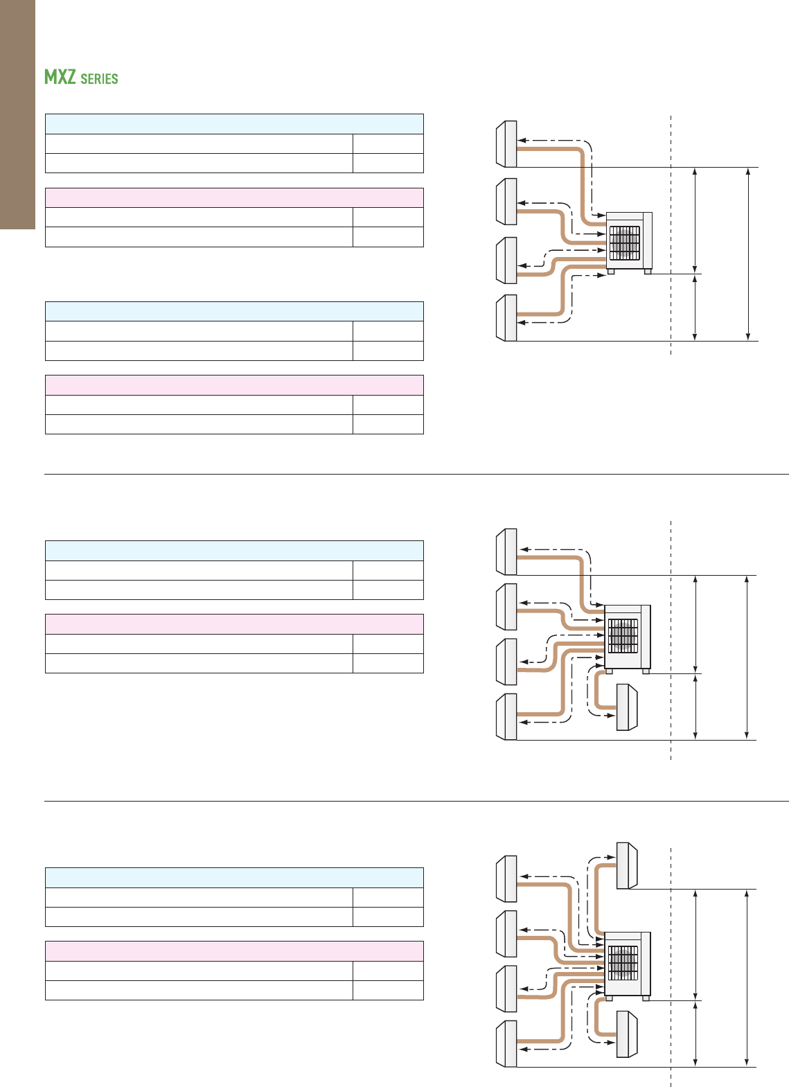
139
Outdoor unit - Indoor unit (a,b)
Total length (a+b)
Outdoor unit - Indoor unit (a,b)
Total number (a+b)
Outdoor unit - Indoor unit (a,b,c)
Total length (a+b+c)
Outdoor unit - Indoor unit (a,b,c)
Total number (a+b+c)
Maximum Piping Length
Maximum Number of Bends
Maximum Piping Length
Maximum Number of Bends
*Only MSZ-HJ model is connectable.
*Only MSZ-HJ model is connectable.
25m
50m
25
50
MXZ-3DM50VA
20m
30m
20
30
a
b
c
Outdoor
unit
Indoor
units
(MSZ-HJ*)
a
b
Outdoor
unit
Indoor
units
(MSZ-HJ*)
Outdoor unit
|
Indoor unit
15m
Outdoor unit
|
Indoor unit
10m
Indoor unit
|
Indoor unit
15m
Outdoor unit
installed lower
Outdoor unit
installed higher
Outdoor unit
|
Indoor unit
15m
Outdoor unit
|
Indoor unit
10m
Indoor unit
|
Indoor unit
15m
Outdoor unit
installed lower
Outdoor unit
installed higher
Maximum height
difference
Maximum height
difference
MXZ-2DM40VA
Highest
Lowest
Maximum Piping Length
Maximum Number of Bends
Maximum Piping Length
Maximum Number of Bends
Maximum Piping Length
Maximum Number of Bends
25m
60m
25
60
b
c
Outdoor
unit
25m
70m
25
70
25m
80m
25
80
MXZ-4E83VA, MXZ-4E83VAHZ
b
c
Outdoor
unit
e
Indoor
units
Indoor
units
MXZ-5E102VA
Outdoor unit - Indoor unit (a,b,c,d)
Total length (a+b+c+d)
Outdoor unit - Indoor unit (a,b,c,d)
Total number (a+b+c+d)
Outdoor unit - Indoor unit (a,b,c,d)
Total length (a+b+c+d)
Outdoor unit - Indoor unit (a,b,c,d)
Total number (a+b+c+d)
Outdoor unit - Indoor unit (a,b,c,d,e)
Total length (a+b+c+d+e)
Outdoor unit - Indoor unit (a,b,c,d,e)
Total number (a+b+c+d+e)
Maximum height
difference
Maximum height
difference
a
d
Outdoor unit
|
Indoor unit
15m
Outdoor unit
|
Indoor unit
10m
Indoor unit
|
Indoor unit
15m
*Outdoor unit
installed lower
*Outdoor unit
installed higher
Outdoor unit
|
Indoor unit
15m
Outdoor unit
|
Indoor unit
10m
Indoor unit
|
Indoor unit
15m
*Outdoor unit
installed lower
*Outdoor unit
installed higher
MXZ-4E72VA
Lowest
Highest
a
d
Lowest
Highest
Maximum Piping Length
Maximum Number of Bends
25m
80m
25
80
b
c
Outdoor
unit
f
e
Indoor
units
MXZ-6D122VA
Outdoor unit - Indoor unit (a,b,c,d,e,f)
Total length (a+b+c+d+e+f)
Outdoor unit - Indoor unit (a,b,c,d,e,f)
Total number (a+b+c+d+e+f)
Maximum height
difference
Outdoor unit
|
Indoor unit
15m
Outdoor unit
|
Indoor unit
10m
Indoor unit
|
Indoor unit
15m
*Outdoor unit
installed lower
*Outdoor unit
installed higher
a
d
Lowest
Highest
* When connecting MFZ-KJ Series indoor unit, additional refrigerant is required. For details, please contact Mitsubishi Electric.
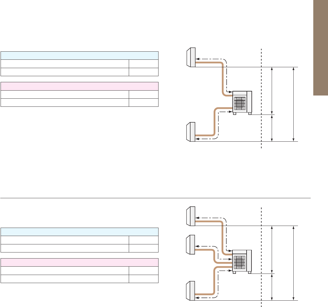
140
Outdoor unit - Indoor unit (a,b)
Total length (a+b)
Outdoor unit - Indoor unit (a,b)
Total number (a+b)
Outdoor unit - Indoor unit (a,b,c)
Total length (a+b+c)
Outdoor unit - Indoor unit (a,b,c)
Total number (a+b+c)
Maximum Piping Length
Maximum Number of Bends
Maximum Piping Length
Maximum Number of Bends
*Only MSZ-HJ model is connectable.
*Only MSZ-HJ model is connectable.
25m
50m
25
50
MXZ-3DM50VA
20m
30m
20
30
a
b
c
Outdoor
unit
Indoor
units
(MSZ-HJ*)
a
b
Outdoor
unit
Indoor
units
(MSZ-HJ*)
Outdoor unit
|
Indoor unit
15m
Outdoor unit
|
Indoor unit
10m
Indoor unit
|
Indoor unit
15m
Outdoor unit
installed lower
Outdoor unit
installed higher
Outdoor unit
|
Indoor unit
15m
Outdoor unit
|
Indoor unit
10m
Indoor unit
|
Indoor unit
15m
Outdoor unit
installed lower
Outdoor unit
installed higher
Maximum height
difference
Maximum height
difference
MXZ-2DM40VA
Highest
Lowest
Maximum Piping Length
Maximum Number of Bends
Maximum Piping Length
Maximum Number of Bends
Maximum Piping Length
Maximum Number of Bends
25m
60m
25
60
b
c
Outdoor
unit
25m
70m
25
70
25m
80m
25
80
MXZ-4E83VA, MXZ-4E83VAHZ
b
c
Outdoor
unit
e
Indoor
units
Indoor
units
MXZ-5E102VA
Outdoor unit - Indoor unit (a,b,c,d)
Total length (a+b+c+d)
Outdoor unit - Indoor unit (a,b,c,d)
Total number (a+b+c+d)
Outdoor unit - Indoor unit (a,b,c,d)
Total length (a+b+c+d)
Outdoor unit - Indoor unit (a,b,c,d)
Total number (a+b+c+d)
Outdoor unit - Indoor unit (a,b,c,d,e)
Total length (a+b+c+d+e)
Outdoor unit - Indoor unit (a,b,c,d,e)
Total number (a+b+c+d+e)
Maximum height
difference
Maximum height
difference
a
d
Outdoor unit
|
Indoor unit
15m
Outdoor unit
|
Indoor unit
10m
Indoor unit
|
Indoor unit
15m
*Outdoor unit
installed lower
*Outdoor unit
installed higher
Outdoor unit
|
Indoor unit
15m
Outdoor unit
|
Indoor unit
10m
Indoor unit
|
Indoor unit
15m
*Outdoor unit
installed lower
*Outdoor unit
installed higher
MXZ-4E72VA
Lowest
Highest
a
d
Lowest
Highest
Maximum Piping Length
Maximum Number of Bends
25m
80m
25
80
b
c
Outdoor
unit
f
e
Indoor
units
MXZ-6D122VA
Outdoor unit - Indoor unit (a,b,c,d,e,f)
Total length (a+b+c+d+e+f)
Outdoor unit - Indoor unit (a,b,c,d,e,f)
Total number (a+b+c+d+e+f)
Maximum height
difference
Outdoor unit
|
Indoor unit
15m
Outdoor unit
|
Indoor unit
10m
Indoor unit
|
Indoor unit
15m
*Outdoor unit
installed lower
*Outdoor unit
installed higher
a
d
Lowest
Highest
* When connecting MFZ-KJ Series indoor unit, additional refrigerant is required. For details, please contact Mitsubishi Electric.
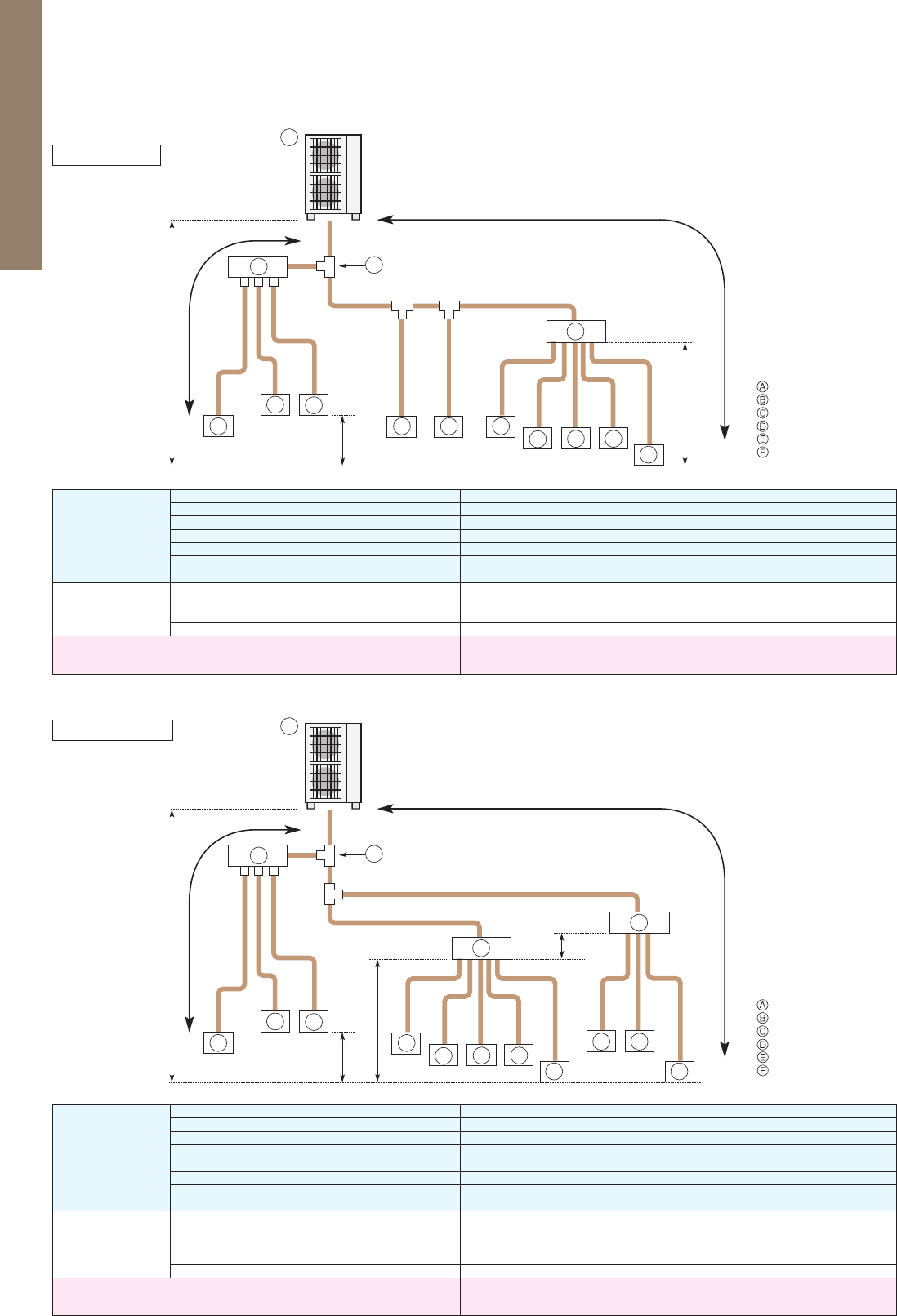
141
Permissible length
(One-way)
Total piping length
e1 + d1 + d2 + c1 + c2 + b1 + b2 + a1 + a2 + a3 + a4 + a5 + a6 + a7 + a8 300 m
Farthest piping length (L1)
e1 + d2 + a1 or e1 + d1 + c1 + b2 85 m
Farthest piping length. Via Branch box (L2)
e1 + d1 + c1 + b1 + a8 80 m
Piping length between outdoor unit and branch box
e1 + d1 + c1 + b1 55 m
Farthest piping length from the first joint
d1 + c1 + b1 or d1 + c1 + b2 30 m
Farthest piping length after branch box
a8 25 m
Total piping length between branch boxes and indoor units
a4 + a5 + a6 + a7 + a8 95 m
Permissible height
difference (One-way)
In indoor/outdoor section (H)*1
H 50 m (In case of outdoor unit is set higher than indoor unit)
H 40 m (In case of outdoor unit is set lower than indoor unit)
In branch box/indoor unit section (h1)
h1 15 m
In each indoor unit (h3)
h3 12 m
Number of bends
|e1 + d2 + a1|, |e1 + d2 + a2|, |e1 + d2 + a3|, |e1 + d1 + c2|, |e1 + d1 + c1 + b2|,
|e1 + d1 + c1 + b1 + a4|, |e1 + d1 + c1 + b1 + a5|, |e1 + d1 + c1 + b1 + a6|,
|e1 + d1 + c1 + b1 + a7|, |e1 + d1 + c1 + b1 + a8| 15
*1: Branch box should be placed within the level between the outdoor unit and indoor units.
Permissible length
(One-way)
Total piping length
d1 + c1 + c2 + b1 + b2 + a1 + a2 + a3 + a4 + a5 + a6 + a7 + a8 + a9 + a10 + a11 240 m
Farthest piping length (L1)
d1 + c1 + a1 85 m
Farthest piping length. Via Branch box (L2)
d1 + c2 + b2 + a11 80 m
Piping length between outdoor unit and branch boxes
d1 + c2 + b1 + b2 55 m
Farthest piping length from the first joint
c2 + b2 or c1 + a1 30 m
Farthest piping length after branch box
a11 25 m
Farthest branch box from outdoor unit
d1 + c2 + b2 55 m
Total piping length between branch boxes and indoor units
a4 + a5 + a6 + a7 + a8 + a9 + a10 + a11 95 m
Permissible height
difference
(One-way)
In indoor/outdoor section (H)*1
H 50 m (In case of outdoor unit is set higher than indoor unit)
H 40 m (In case of outdoor unit is set lower than indoor unit)
In branch box/indoor unit section (h1)
h1 + h2 15 m
In each branch unit (h2)
h2 15 m
In each indoor unit (h3)
h3 12 m
Number of bends
|d1 + c1 + a1|, |d1 + c1 + a2|, |d1 + c1 + a3|, |d1 + c2 + b1 + a4|, |d1 + c2 + b1 + a5|,
|d1 + c2 + b1 + a6|, |d1 + c2 + b1 + a7|, |d1 + c2 + b1 + a8|, |d1 + c2 + b2 + a9|,
|d1 + c2 + b2 + a10|, |d1 + c2 + b2 + a11| 15
*1: Branch box should be placed within the level between the outdoor unit and indoor units.
<
=
<
=
<
=
<
=
<
=
<
=
<
=
<
=
<
=
<
=
<
=
<
=
<
=
<
=
<
=
<
=
<
=
<
=
<
=
<
=
<
=
<
=
<
=
<
=
<
=
<
=
PUMY-P112/125/140V
(
Y
)
KM2
1-Branch box
2-Branch boxes
PUMY SERIES
b1
L2
L1
c1
d1
e1
d2
h3
H
a4b2
a5 a6 a7
a8
F
FE
D
FF
A
F
h1
a1
a2 a3
E
E
E
c2
E
L2
L1
d1
c2
c1
h3
h2
H
a4
a5 a6 a7
a8
F
a11
F
F
D
FF
D
F
A
F
a9
F
h1
a1
a2 a3
E
E
C
B
E
a10
Outdoor Unit
First joint
Branch header (CMY)
Branch box (PAC-MK31/51)
CITY MULTI Indoor unit
M/S/P series Indoor unit
Outdoor Unit
First joint
Branch header (CMY)
Branch box (PAC-MK31/51)
CITY MULTI Indoor unit
M/S/P series Indoor unit
C
B
Explanation of Terminology
Maximum piping length:
This is the maximum allowable length of the refrigerant piping. The amount of refrigerant pipe used cannot be longer than the
length specified.
Total length:
The maximum allowable combined length of all the refrigerant piping between the outdoor unit and indoor unit(s).
Outdoor Unit - Indoor Unit:
The maximum allowable length of the refrigerant piping between the outdoor unit and indoor units installed when multiple units are connec-
ted to a single outdoor unit. This distance limitation refers to the maximum length between the outdoor unit and the farthest indoor unit.
Pipe length difference from distribution pipe:
The maximum allowable difference in refrigerant piping length from the distribution pipe to the farthest indoor unit and from the distribution
pipe to the closest indoor unit when multiple indoor units are connected to a single outdoor unit using a distribution pipe.
Indoor Unit - Distribution Pipe:
The maximum allowable length of the refrigerant piping between indoor units and the distribution pipe when multiple indoor units are
connected to a single outdoor unit.
Maximum height difference:
This is the maximum allowable height difference. It is necessary to install the air conditioning system so that the height distance
is no more than the difference specified. (Specified differences may vary if the outdoor unit is installed higher or lower than the
indoor units).
Outdoor unit - Indoor unit:
The maximum allowable difference in height between the outdoor unit and indoor units when installed (when multiple indoor units are con-
nected to a single outdoor unit, this distance limitation refers to the maximum height difference between the outdoor unit and an indoor unit).
Indoor unit - Indoor unit:
The maximum allowable difference between the heights of indoor units when multiple indoor units are connected to a single outdoor unit.
Maximum number of bends:
This is the maximum allowable number of bends in the refrigerant piping. The total number of bends in the refrigerant piping
used cannot exceed the number specified.
Total number:
The maximum allowable number of bends for all refrigerant piping between the outdoor unit and indoor units.
Outdoor unit - Indoor unit:
The maximum allowable number of bends between the outdoor unit and each indoor unit when multiple indoor units are connected
to a single outdoor unit.

142
Permissible length
(One-way)
Total piping length
e1 + d1 + d2 + c1 + c2 + b1 + b2 + a1 + a2 + a3 + a4 + a5 + a6 + a7 + a8 300 m
Farthest piping length (L1)
e1 + d2 + a1 or e1 + d1 + c1 + b2 85 m
Farthest piping length. Via Branch box (L2)
e1 + d1 + c1 + b1 + a8 80 m
Piping length between outdoor unit and branch box
e1 + d1 + c1 + b1 55 m
Farthest piping length from the first joint
d1 + c1 + b1 or d1 + c1 + b2 30 m
Farthest piping length after branch box
a8 25 m
Total piping length between branch boxes and indoor units
a4 + a5 + a6 + a7 + a8 95 m
Permissible height
difference (One-way)
In indoor/outdoor section (H)*1
H 50 m (In case of outdoor unit is set higher than indoor unit)
H 40 m (In case of outdoor unit is set lower than indoor unit)
In branch box/indoor unit section (h1)
h1 15 m
In each indoor unit (h3)
h3 12 m
Number of bends
|e1 + d2 + a1|, |e1 + d2 + a2|, |e1 + d2 + a3|, |e1 + d1 + c2|, |e1 + d1 + c1 + b2|,
|e1 + d1 + c1 + b1 + a4|, |e1 + d1 + c1 + b1 + a5|, |e1 + d1 + c1 + b1 + a6|,
|e1 + d1 + c1 + b1 + a7|, |e1 + d1 + c1 + b1 + a8| 15
*1: Branch box should be placed within the level between the outdoor unit and indoor units.
Permissible length
(One-way)
Total piping length
d1 + c1 + c2 + b1 + b2 + a1 + a2 + a3 + a4 + a5 + a6 + a7 + a8 + a9 + a10 + a11 240 m
Farthest piping length (L1)
d1 + c1 + a1 85 m
Farthest piping length. Via Branch box (L2)
d1 + c2 + b2 + a11 80 m
Piping length between outdoor unit and branch boxes
d1 + c2 + b1 + b2 55 m
Farthest piping length from the first joint
c2 + b2 or c1 + a1 30 m
Farthest piping length after branch box
a11 25 m
Farthest branch box from outdoor unit
d1 + c2 + b2 55 m
Total piping length between branch boxes and indoor units
a4 + a5 + a6 + a7 + a8 + a9 + a10 + a11 95 m
Permissible height
difference
(One-way)
In indoor/outdoor section (H)*1
H 50 m (In case of outdoor unit is set higher than indoor unit)
H 40 m (In case of outdoor unit is set lower than indoor unit)
In branch box/indoor unit section (h1)
h1 + h2 15 m
In each branch unit (h2)
h2 15 m
In each indoor unit (h3)
h3 12 m
Number of bends
|d1 + c1 + a1|, |d1 + c1 + a2|, |d1 + c1 + a3|, |d1 + c2 + b1 + a4|, |d1 + c2 + b1 + a5|,
|d1 + c2 + b1 + a6|, |d1 + c2 + b1 + a7|, |d1 + c2 + b1 + a8|, |d1 + c2 + b2 + a9|,
|d1 + c2 + b2 + a10|, |d1 + c2 + b2 + a11| 15
*1: Branch box should be placed within the level between the outdoor unit and indoor units.
<
=
<
=
<
=
<
=
<
=
<
=
<
=
<
=
<
=
<
=
<
=
<
=
<
=
<
=
<
=
<
=
<
=
<
=
<
=
<
=
<
=
<
=
<
=
<
=
<
=
<
=
PUMY-P112/125/140V
(
Y
)
KM2
1-Branch box
2-Branch boxes
PUMY SERIES
b1
L2
L1
c1
d1
e1
d2
h3
H
a4b2
a5 a6 a7
a8
F
FE
D
FF
A
F
h1
a1
a2 a3
E
E
E
c2
E
L2
L1
d1
c2
c1
h3
h2
H
a4
a5 a6 a7
a8
F
a11
F
F
D
FF
D
F
A
F
a9
F
h1
a1
a2 a3
E
E
C
B
E
a10
Outdoor Unit
First joint
Branch header (CMY)
Branch box (PAC-MK31/51)
CITY MULTI Indoor unit
M/S/P series Indoor unit
Outdoor Unit
First joint
Branch header (CMY)
Branch box (PAC-MK31/51)
CITY MULTI Indoor unit
M/S/P series Indoor unit
C
B
Explanation of Terminology
Maximum piping length:
This is the maximum allowable length of the refrigerant piping. The amount of refrigerant pipe used cannot be longer than the
length specified.
Total length:
The maximum allowable combined length of all the refrigerant piping between the outdoor unit and indoor unit(s).
Outdoor Unit - Indoor Unit:
The maximum allowable length of the refrigerant piping between the outdoor unit and indoor units installed when multiple units are connec-
ted to a single outdoor unit. This distance limitation refers to the maximum length between the outdoor unit and the farthest indoor unit.
Pipe length difference from distribution pipe:
The maximum allowable difference in refrigerant piping length from the distribution pipe to the farthest indoor unit and from the distribution
pipe to the closest indoor unit when multiple indoor units are connected to a single outdoor unit using a distribution pipe.
Indoor Unit - Distribution Pipe:
The maximum allowable length of the refrigerant piping between indoor units and the distribution pipe when multiple indoor units are
connected to a single outdoor unit.
Maximum height difference:
This is the maximum allowable height difference. It is necessary to install the air conditioning system so that the height distance
is no more than the difference specified. (Specified differences may vary if the outdoor unit is installed higher or lower than the
indoor units).
Outdoor unit - Indoor unit:
The maximum allowable difference in height between the outdoor unit and indoor units when installed (when multiple indoor units are con-
nected to a single outdoor unit, this distance limitation refers to the maximum height difference between the outdoor unit and an indoor unit).
Indoor unit - Indoor unit:
The maximum allowable difference between the heights of indoor units when multiple indoor units are connected to a single outdoor unit.
Maximum number of bends:
This is the maximum allowable number of bends in the refrigerant piping. The total number of bends in the refrigerant piping
used cannot exceed the number specified.
Total number:
The maximum allowable number of bends for all refrigerant piping between the outdoor unit and indoor units.
Outdoor unit - Indoor unit:
The maximum allowable number of bends between the outdoor unit and each indoor unit when multiple indoor units are connected
to a single outdoor unit.
143
ECODAN
“ECODAN” can heat rooms and supply domestic
hot water, realising greater comfort and energy saving.
Both energy-saving and safe for the environment, the Mitsubishi Electric ECODAN incorporates a highly efficient heat pump
system that captures “the heat in the air”, a renewable energy resource. Equipped with advanced inverter
control, meticulous
temperature control assures comfortable heating, and its space-saving “All-in-one” indoor unit is easy to install.
These energy-
saving, high comfort and simple installation characteristics have drawn the ECODAN heating system into the spotlight centre
stage.
Excellent ECODAN’s heating performance, even at low outdoor temperature!
“ECODAN” – Economic, eco conscious next generation heating system
OUTDOOR UNIT
INDOOR UNIT
Small capacity
(
Under 5kW
)*
Split type Medium capacity
(
7.5 k W –14kW
)*
Large capacity*
PUHZ-W50 PUHZ-W85 PUHZ-W112
PUHZ-HW112/140
PUHZ-FRP71
SUHZ-SW45
PUHZ-SW50 PUHZ-SW75 PUHZ-SW100/120 PUHZ-SW160/200
PUHZ-SHW80/112/140 PUHZ-SHW230
Small capacity
(
Under 5kW
)*
Packaged type Medium capacity
(
7.5 k W –14kW
)*
Reversible hydro box,
Reversible cylinder unit
Hydro box, cylinder unit
Eco
Inverter
* Rated capacity is at conditions A2W35.
(
according to EN14511
)
Large capacity
(
16kW
)*
>
=
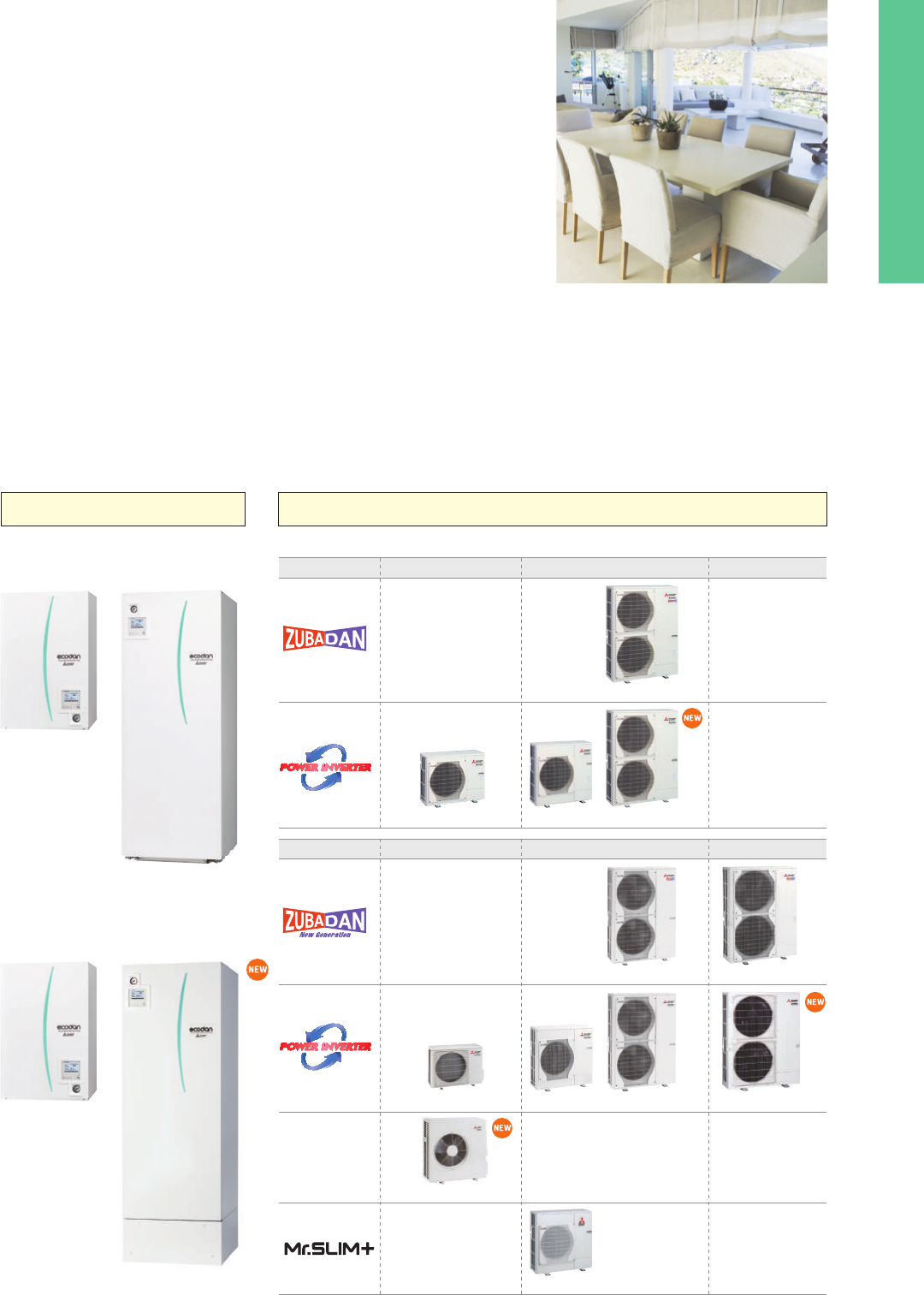
144
ECODAN
“ECODAN” can heat rooms and supply domestic
hot water, realising greater comfort and energy saving.
Both energy-saving and safe for the environment, the Mitsubishi Electric ECODAN incorporates a highly efficient heat pump
system that captures “the heat in the air”, a renewable energy resource. Equipped with advanced inverter
control, meticulous
temperature control assures comfortable heating, and its space-saving “All-in-one” indoor unit is easy to install.
These energy-
saving, high comfort and simple installation characteristics have drawn the ECODAN heating system into the spotlight centre
stage.
Excellent ECODAN’s heating performance, even at low outdoor temperature!
“ECODAN” – Economic, eco conscious next generation heating system
OUTDOOR UNIT
INDOOR UNIT
Small capacity
(
Under 5kW
)*
Split type Medium capacity
(
7.5 k W –14kW
)*
Large capacity*
PUHZ-W50 PUHZ-W85 PUHZ-W112
PUHZ-HW112/140
PUHZ-FRP71
SUHZ-SW45
PUHZ-SW50 PUHZ-SW75 PUHZ-SW100/120 PUHZ-SW160/200
PUHZ-SHW80/112/140 PUHZ-SHW230
Small capacity
(
Under 5kW
)*
Packaged type Medium capacity
(
7.5 k W –14kW
)*
Reversible hydro box,
Reversible cylinder unit
Hydro box, cylinder unit
Eco
Inverter
* Rated capacity is at conditions A2W35.
(
according to EN14511
)
Large capacity
(
16kW
)*
>
=
145
What is the ErP Directive?
ZUBADAN New Generation (Split type)
Reliable performance in low-temperature outdoor air
ZUBADAN New Generation provides powerful
heating in cold regions where most heat pumps
cannot perform very well. Its rated heating capacity
is maintained even in outdoor temperatures as low
as –15°C, even when flow temperature needs to
be higher. That means it can be trusted to provide
comfortable heating during severe winter months.
The Ecodesign Directive for Energy-related Products (ErP Directive) established a framework to set mandatory standards for ErPs sold in the Euro-
pean Union (EU). The ErP Directive introduces new energy efficiency ratings across various product categories. It affects how products such as
computers, vacuum cleaners, boilers and even windows are classified in terms of environmental performance. Labelling regulations that apply to
our ATW heat pumps come into effect as of September 26, 2015.
Under directive 2009/125/EC, ATW heat pumps of up to
70kW are required to show their heating efficiency on the
energy label. The purpose of the energy label is to inform
customers about the energy efficiency of a heating unit.
The efficiency for space heating is ranked from A
++
to G.
In the case of domestic hot water, it is from A to G.
A package label is also required if the ECODAN heat pump
is installed with a controller and/or a solar system or addi-
tional heater. All ECODAN units* are already rated as A
++
for heating at both 55°C and 35°C and A for domestic hot
water, which are the highest efficiency ranks.
*Except for our ATA/ATW hybrid system Mr. SLIM+
New energy label and measurements
New eco-design directive
Designed for Optimal Heating
Heat pump space heater label
These labels are delivered with all ECODAN outdoor units.
Combination heater label
Manufacturer
Symbol for
domestic hot water
DHW efficiency during
medium-temperature
operation
Outdoor and indoor unit
model name
Symbol for space heating
Heating efficiency in
low-flow temperature operation
Heating efficiency in
medium-flow temperature operation
Indoor and outdoor unit
operating sound power level values
Rated heat output
(
kW
)
under average,
colder and warmer conditions
European temperature
climate map
This label is for individual heating units, such as an ECODAN heat pump. Typically, the space
heater label is used for ECODAN systems with a hydro box, and the combination heater label
is used for ECODAN systems with a cylinder unit.
Product label
A heating system can use several energy-related prod-
ucts, such as a controller or solar thermal system. There-
fore, a label showing the efficiency of the total heating
system is required. The category range is defined from
A
+++
to G.
Creating the package label is the responsibility of the in-
stallers and distributors. A useful tool on the Mitsubishi
Electric website is available to easily create the labels for
ECODAN products and controllers.
erp.mitsubishielectric.eu/erp/options
What is the package label?
This label is for heating systems that use several energy-related products, such as a controller
or a solar thermal system.
Package label
Customised package labels including ECODAN heat pumps and FTC5 controller
can be created on the Mitsubishi Electric website.
Package space heater label Package combination heater label
+
+
+
+
A
+++
A
++
A
+
A
B
C
D
E
F
G
2015 811/2013
A
+++
A
++
Sample Sample-1
X
X
X
X
A
+++
A
++
A
+
A
B
C
D
E
F
G
A
+++
A
++
A
+
A
B
C
D
E
F
G
+
+
+
+
2015 811/2013
A
+++
A
+++
A
++
A
Sample Sample-2
X
X
X
X
L
L
with solar thermal system
with hot-water storage tank
with temperature controller
with auxiliary heating units
The Flash Injection Circuit is an original tech-
nology. A heat exchange process at point A
(
heat interchanger
)
transforms liquid refriger-
ant into a two-phase, gas-liquid state and
then compresses the gas-liquid refrigerant
at point B (injection compressor). This circuit
secures a sufficient flow rate of refrigerant
for heating when outdoor temperatures are
very low. Thanks to improving the heat inter-
changer and introducing a new injection com-
pressor, the Flash Injection Circuit is now
more powerful.
Thanks to the unique plate heat exchanger and scale trap technology, a more efficient
performance is achieved. In conventional systems, there is a risk of calcium scale building
up on the heat-exchange plate if it is exposed to tap water directly. Therefore, it is difficult
to use plate-based heat exchangers to heat tap water. To resolve this problem, ECODAN
is equipped with a “scale trap” that catches homogeneous calcium nuclei in the tap water
before it has a chance to grow into large scales, thereby inhibiting build-up in the external
heat exchanger. ECODAN can use a plate heat exchanger to heat tap water, resulting in
much higher domestic hot water performance.
Notice: In the case of the special conditions such as very hard tap water, please consult with a specialist
before installation.
Mitsubishi Electric’s
Flash Injection Technology
The key to high heating
performance at low
outdoor temperatures
Heat interchanger
(
HIC
)
Injection compressor
A
B
Flash Injection Circuit
LEVB
LEVC
LEVA
Heat
interchanger (HIC)
A
B
Indoor
HEX
Power
receiver
Outdoor
HEX
Injection compressor
(injection port)
Flash Injection Circuit
ZUBADAN New Generation
Flash Injection Circuit
Refrigerant flow
ZUBADAN New Generation
Previous model
Integrated
capacity (kW)
Outdoor-air temperature at intake duct
W45 (according to EN 14511)
9
-7°C-15°C-20°C-28°C 0°C
10
11
12
13
14
15
Approx. 22% higher than
our previous model !
Nominal capacity can
be kept at -15ºC !
Example:
PUHZ-SHW140YHA
● Benefits ZUBADAN
New Generation
New all-in-one compact indoor unit
Indoor units
Larger capacity system
Easy to install and low maintenance
• All-in-one: Key functional components are incorporated
• Compact cylinder unit: Just 1600mm in height
• Compact hydro box: Only 600×600mm footprint
• Easy installation: Factory fitted pressure relief valve
• Easy service: Relevant parts are located at the front of
the unit for easy maintenance
• Easy transport: Handles attached on front and back
(cylinder unit)
External plate heat exchanger – more energy savings using ECODAN’s unique and
innovative technologies
High-performance for domestic hot water re-charge
*Depending on model
Hydro box (Split type)
Cylinder unit (Split type)
Water pump
Manometer
Booster heater*
Water pump
Plate heat
exchanger
Strainer
Adjustable feet
Expansion vessel*
Expansion vessel*
Booster heater*
Manometer
Domestic hot water
plate heat exchanger
Domestic
hot water pump
Tank
3-way valve
Scale trap
Plate heat
exchanger
Strainer
Outdoor units
PUHZ-SW160/200YKA
SHW230YKA2
Indoor units
EHSE-YM9EC, EHSE-MEC, ERSE-YM9EC, ERSE-MEC
Our 8–10HP ECODAN heat pumps, only available with a hydro box connection,
are suitable for large houses and small businesses where a high heating load
is necessary. Our latest generation of 8–10HP Power Inverter outdoor units
can now reach 60°C maximum flow temperature instead of 53°C previously.
The new 8–10HP hydro box is available in both heating only and reversible and
can be connected to a customised capacity domestic hot water tank.
The secret behind our external plate heat exchanger system
External P-HEX circuit
P-HEX
Scale Trap
Circulating Water
Hot Water
Fresh Water
DHW Storage Tank
Tap Water
Pump
140%
120%
100
%
80%
60%
40%
20%
0%
0 2 4 6 8 10 12 14 year
Usage condition
COP
(recharging)
<
Our test result
>
Tank temperature: 10 degree to 60 degree
Heating up time: 1 hour per 1 day
Supersaturation of CaCO
3: 50
*15 years accelerated testing
<
*
1,
*
2
>
Our new model (External heat exchanger with scale trap)
Initial performance level of previous model
(
Coil in tank
)
Save energy in domestic hot water operations
Thanks to an external plate heat exchanger, ECODAN offers much higher domestic
hot water efficiency. Compared to our previous model, domestic hot water recharge
efficiency is improved by approximately 17%*
1
, thereby reducing operating costs.
Avoid performance loss due to scale
A scale trap is incorporated after the plate heat exchanger to capture calcium scale
particles, thus maintaining the high performance of the external plate heat exchang-
er. (Just a 3% reduction during 15 years*
2
).
Lighter weight
Compared to our previous model, the cylinder unit is up to 15kg lighter*.
This is thanks to the coil incorporated in the tank which has been removed and re-
placed by a much lighter plate heat exchanger.
*Comparison between EHST20C-VM2C and EHST20C-VM2B.
Optimised stratification for better comfort
Thanks to the L-shaped inlet pipe from the plate heat exchanger, stratification is well maintained after re-charge.
You do not need to worry about running out of hot water the same as with a conventional coil in tank.
Supply water temperature can be kept high until all the hot water in the tank has been used.
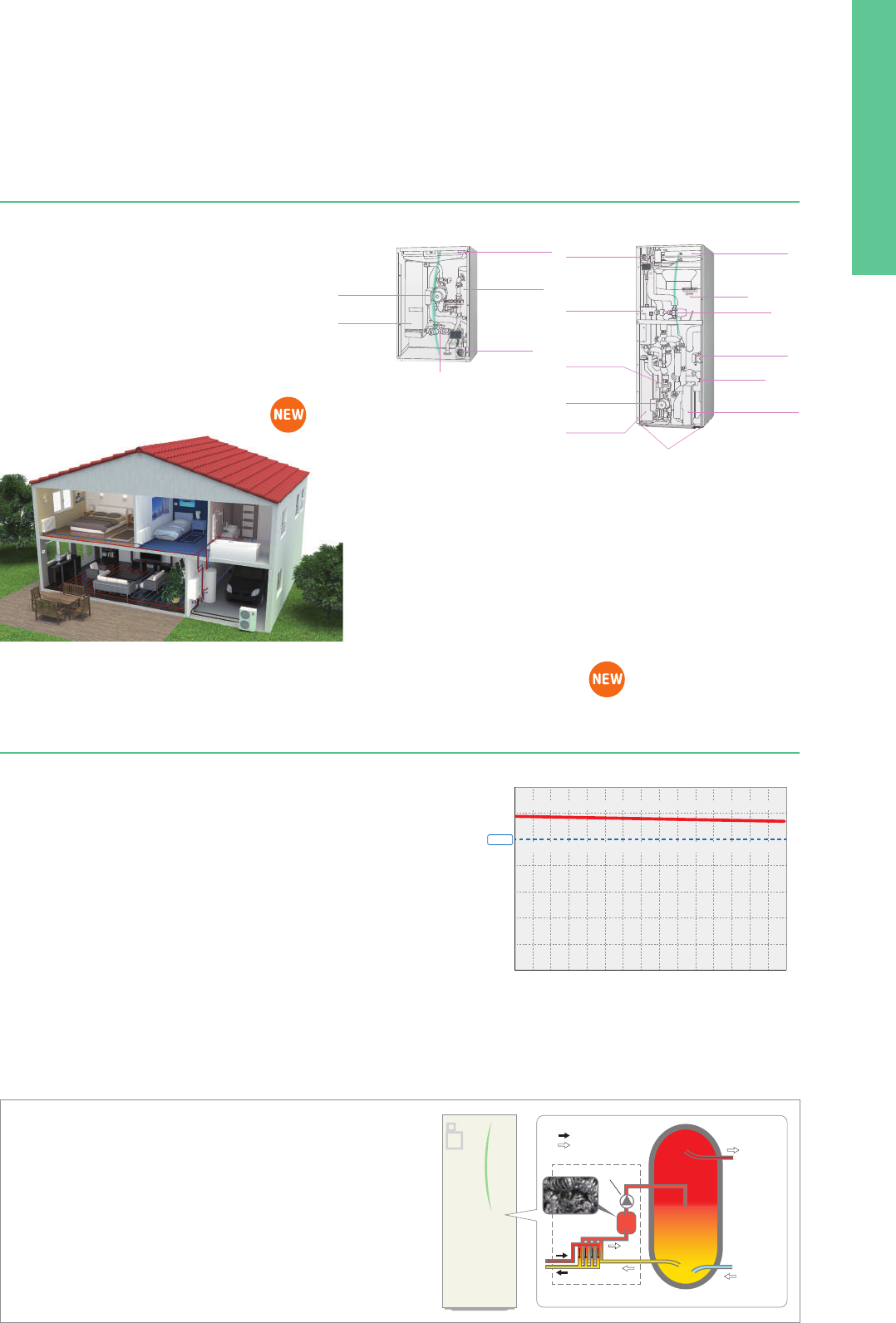
146
What is the ErP Directive?
ZUBADAN New Generation (Split type)
Reliable performance in low-temperature outdoor air
ZUBADAN New Generation provides powerful
heating in cold regions where most heat pumps
cannot perform very well. Its rated heating capacity
is maintained even in outdoor temperatures as low
as –15°C, even when flow temperature needs to
be higher. That means it can be trusted to provide
comfortable heating during severe winter months.
The Ecodesign Directive for Energy-related Products (ErP Directive) established a framework to set mandatory standards for ErPs sold in the Euro-
pean Union (EU). The ErP Directive introduces new energy efficiency ratings across various product categories. It affects how products such as
computers, vacuum cleaners, boilers and even windows are classified in terms of environmental performance. Labelling regulations that apply to
our ATW heat pumps come into effect as of September 26, 2015.
Under directive 2009/125/EC, ATW heat pumps of up to
70kW are required to show their heating efficiency on the
energy label. The purpose of the energy label is to inform
customers about the energy efficiency of a heating unit.
The efficiency for space heating is ranked from A
++
to G.
In the case of domestic hot water, it is from A to G.
A package label is also required if the ECODAN heat pump
is installed with a controller and/or a solar system or addi-
tional heater. All ECODAN units* are already rated as A
++
for heating at both 55°C and 35°C and A for domestic hot
water, which are the highest efficiency ranks.
*Except for our ATA/ATW hybrid system Mr. SLIM+
New energy label and measurements
New eco-design directive
Designed for Optimal Heating
Heat pump space heater label
These labels are delivered with all ECODAN outdoor units.
Combination heater label
Manufacturer
Symbol for
domestic hot water
DHW efficiency during
medium-temperature
operation
Outdoor and indoor unit
model name
Symbol for space heating
Heating efficiency in
low-flow temperature operation
Heating efficiency in
medium-flow temperature operation
Indoor and outdoor unit
operating sound power level values
Rated heat output
(
kW
)
under average,
colder and warmer conditions
European temperature
climate map
This label is for individual heating units, such as an ECODAN heat pump. Typically, the space
heater label is used for ECODAN systems with a hydro box, and the combination heater label
is used for ECODAN systems with a cylinder unit.
Product label
A heating system can use several energy-related prod-
ucts, such as a controller or solar thermal system. There-
fore, a label showing the efficiency of the total heating
system is required. The category range is defined from
A
+++
to G.
Creating the package label is the responsibility of the in-
stallers and distributors. A useful tool on the Mitsubishi
Electric website is available to easily create the labels for
ECODAN products and controllers.
erp.mitsubishielectric.eu/erp/options
What is the package label?
This label is for heating systems that use several energy-related products, such as a controller
or a solar thermal system.
Package label
Customised package labels including ECODAN heat pumps and FTC5 controller
can be created on the Mitsubishi Electric website.
Package space heater label Package combination heater label
+
+
+
+
A
+++
A
++
A
+
A
B
C
D
E
F
G
2015 811/2013
A
+++
A
++
Sample Sample-1
X
X
X
X
A
+++
A
++
A
+
A
B
C
D
E
F
G
A
+++
A
++
A
+
A
B
C
D
E
F
G
+
+
+
+
2015 811/2013
A
+++
A
+++
A
++
A
Sample Sample-2
X
X
X
X
L
L
with solar thermal system
with hot-water storage tank
with temperature controller
with auxiliary heating units
The Flash Injection Circuit is an original tech-
nology. A heat exchange process at point A
(
heat interchanger
)
transforms liquid refriger-
ant into a two-phase, gas-liquid state and
then compresses the gas-liquid refrigerant
at point B (injection compressor). This circuit
secures a sufficient flow rate of refrigerant
for heating when outdoor temperatures are
very low. Thanks to improving the heat inter-
changer and introducing a new injection com-
pressor, the Flash Injection Circuit is now
more powerful.
Thanks to the unique plate heat exchanger and scale trap technology, a more efficient
performance is achieved. In conventional systems, there is a risk of calcium scale building
up on the heat-exchange plate if it is exposed to tap water directly. Therefore, it is difficult
to use plate-based heat exchangers to heat tap water. To resolve this problem, ECODAN
is equipped with a “scale trap” that catches homogeneous calcium nuclei in the tap water
before it has a chance to grow into large scales, thereby inhibiting build-up in the external
heat exchanger. ECODAN can use a plate heat exchanger to heat tap water, resulting in
much higher domestic hot water performance.
Notice: In the case of the special conditions such as very hard tap water, please consult with a specialist
before installation.
Mitsubishi Electric’s
Flash Injection Technology
The key to high heating
performance at low
outdoor temperatures
Heat interchanger
(
HIC
)
Injection compressor
A
B
Flash Injection Circuit
LEVB
LEVC
LEVA
Heat
interchanger (HIC)
A
B
Indoor
HEX
Power
receiver
Outdoor
HEX
Injection compressor
(injection port)
Flash Injection Circuit
ZUBADAN New Generation
Flash Injection Circuit
Refrigerant flow
ZUBADAN New Generation
Previous model
Integrated
capacity (kW)
Outdoor-air temperature at intake duct
W45 (according to EN 14511)
9
-7°C-15°C-20°C-28°C 0°C
10
11
12
13
14
15
Approx. 22% higher than
our previous model !
Nominal capacity can
be kept at -15ºC !
Example:
PUHZ-SHW140YHA
● Benefits ZUBADAN
New Generation
New all-in-one compact indoor unit
Indoor units
Larger capacity system
Easy to install and low maintenance
• All-in-one: Key functional components are incorporated
• Compact cylinder unit: Just 1600mm in height
• Compact hydro box: Only 600×600mm footprint
• Easy installation: Factory fitted pressure relief valve
• Easy service: Relevant parts are located at the front of
the unit for easy maintenance
• Easy transport: Handles attached on front and back
(cylinder unit)
External plate heat exchanger – more energy savings using ECODAN’s unique and
innovative technologies
High-performance for domestic hot water re-charge
*Depending on model
Hydro box (Split type)
Cylinder unit (Split type)
Water pump
Manometer
Booster heater*
Water pump
Plate heat
exchanger
Strainer
Adjustable feet
Expansion vessel*
Expansion vessel*
Booster heater*
Manometer
Domestic hot water
plate heat exchanger
Domestic
hot water pump
Tank
3-way valve
Scale trap
Plate heat
exchanger
Strainer
Outdoor units
PUHZ-SW160/200YKA
SHW230YKA2
Indoor units
EHSE-YM9EC, EHSE-MEC, ERSE-YM9EC, ERSE-MEC
Our 8–10HP ECODAN heat pumps, only available with a hydro box connection,
are suitable for large houses and small businesses where a high heating load
is necessary. Our latest generation of 8–10HP Power Inverter outdoor units
can now reach 60°C maximum flow temperature instead of 53°C previously.
The new 8–10HP hydro box is available in both heating only and reversible and
can be connected to a customised capacity domestic hot water tank.
The secret behind our external plate heat exchanger system
External P-HEX circuit
P-HEX
Scale Trap
Circulating Water
Hot Water
Fresh Water
DHW Storage Tank
Tap Water
Pump
140%
120%
100
%
80%
60%
40%
20%
0%
0 2 4 6 8 10 12 14 year
Usage condition
COP
(recharging)
<
Our test result
>
Tank temperature: 10 degree to 60 degree
Heating up time: 1 hour per 1 day
Supersaturation of CaCO
3: 50
*15 years accelerated testing
<
*
1,
*
2
>
Our new model (External heat exchanger with scale trap)
Initial performance level of previous model
(
Coil in tank
)
Save energy in domestic hot water operations
Thanks to an external plate heat exchanger, ECODAN offers much higher domestic
hot water efficiency. Compared to our previous model, domestic hot water recharge
efficiency is improved by approximately 17%*
1
, thereby reducing operating costs.
Avoid performance loss due to scale
A scale trap is incorporated after the plate heat exchanger to capture calcium scale
particles, thus maintaining the high performance of the external plate heat exchang-
er. (Just a 3% reduction during 15 years*
2
).
Lighter weight
Compared to our previous model, the cylinder unit is up to 15kg lighter*.
This is thanks to the coil incorporated in the tank which has been removed and re-
placed by a much lighter plate heat exchanger.
*Comparison between EHST20C-VM2C and EHST20C-VM2B.
Optimised stratification for better comfort
Thanks to the L-shaped inlet pipe from the plate heat exchanger, stratification is well maintained after re-charge.
You do not need to worry about running out of hot water the same as with a conventional coil in tank.
Supply water temperature can be kept high until all the hot water in the tank has been used.
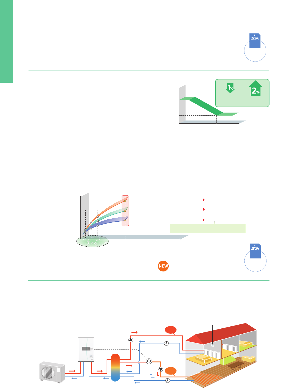
147
An existing boiler can be used for extra heating capacity in an efficient way
The flexibility of ECODAN’s intelligent control allows the system to be combined with the boiler currently in use. Additionally, this control can judge
which heating source to use either ECODAN or the existing boiler, based on various conditions*.
In the event of one heating unit not working due to some unforeseen problem, the other heating system can be used as a back-up, thereby
preventing the heating system operation from stopping completely.
*Please check below “Heat source switchover”.
Connect up to 6 units – Automatic control of multiple units
for bigger capacity and better efficiency
A maximum of 6 units* can be configured according to the heating/cooling load of the building. The most efficient number of operating units is
determined automatically based on heating/cooling load. This enables ECODAN to provide optimal room temperature control, and thus superior
comfort for room occupants. Also incorporated is a rotation function that enables each unit to run for an equal time period.
If one of the units malfunctions when using the Multiple Unit Control, another unit can be automatically operated for back-up, thereby preventing
the system operation from stopping completely.
*Only same models (same capacity) can be used.
Intelligent system combining a boiler with ECODAN
Intelligent boiler interlock
Multiple unit control
■ Multiple unit control
■ Intelligent boiler interlock systen
Settings can be
performed using
an SD card.
*SD logo is a trademark
of SD-3C, LLC
Settings can be
performed using
an SD card.
*SD logo is a trademark
of SD-3C, LLC
*Items such as mixing tank, mixing valve flow switch and pumps are not included and need to be purchased locally.
Wireless remote controller
as thermistor
Radiator
Mixing control
Mixing tank
Hydro Box
FTC
Pump
Pump
Mixing
valve
40°C
30°C
Underfloor heating
Flow Switch
Flow Switch
Maximize energy savings while retaining comfort at all times
Settings can be
performed using
an SD card.
*SD logo is a trademark
of SD-3C, LLC
Auto Adaptation
Regarding the relation of flow temperature and unit performance, a 1°C drop
in the flow temperature improves the coefficient of performance (COP) of the
ATW system by 2%. This means that energy savings are dramatically affected
by controlling the flow temperature in the system.
In a conventional system controller, the flow temperature is determined based
on the pre-set heat curve depending on the actual outdoor temperature. How-
ever, this requires a complicated setting to achieve the optimal heat curve.
Flow temp.
Outdoor temp.
COP is
improved 2%
If flow
temperature is
lowered 1°C
60°C
30°C
-15°C 10°C
(c) Lower than the target room temp.
Room temp.
Target temp.
Time
(b) Approximately same as the target temp.
(a) Higher than the target room temp.
Future
3 points
lower the flow temp.
keep the flow temp.
raise the flow temp.
Modify the flow temperature by comparing
actual and estimated room temperature.
T0 T1 Current
Aiming to realise further comfort and energy savings, Mitsubishi Electric is proud to introduce a revolutionary new controller. Our advanced Auto
Adaptation function measures the room temperature and outdoor temperature, and then calculates the required heating capacity for the room.
Simply stated, the flow temperature is automatically controlled according to the required heating capacity, while optimal room temperature is
maintained at all times, ensuring the appropriate heating capacity and preventing energy from being wasted. Furthermore, by estimating future
changes in room temperature, the system works to prevent unnecessary increases and decreases in the flow temperature.
Accordingly, Auto Adaptation maximises both comfort and energy savings without the need for complicated settings.
Mitsubishi Electric’s Auto Adaptation function automatically tracks changes in the actual room temperature
and outdoor temperature and adjusts the flow temperature accordingly.
■ Future room temperature estimation
■ Heat curve setting (Example)
Unique technology of ECODAN
Simultaneously control two different zones
Two-zone control (for heating/cooling)
■ Two temperature zones
Using ECODAN, it is possible to control two different flow temperatures, thereby managing two different heating load requirements. The system
can adjust and maintain two flow temperatures when different temperatures are required for different rooms; for example, controlling a flow
temperature of 40°C for the bedroom radiators and another flow temperature of 30°C for the living room floor heating.
Another feature of this model is that two-zone cooling control is now possible. Using these functions it is easy to maintain the most comfortable
temperature in each room and to save energy too.
Settings can be
performed using
an SD card.
*SD logo is a trademark
of SD-3C, LLC
Multiple unit control
Main RC
FTC
slave
23kW
+
23kW
+
23kW
+
23kW
+
23kW
+
23kW
FTC
slave
FTC
slave
FTC
slave
FTC
slave
FTC
slave
COP ratio (%)
Total Capacity
100
Multiple unit control
One large unit control
Always high efficient operation !
Inefficient operation
at low capacity.
ON/OFF control
1 unit
2 units
3 units
4 units
5 units
6 units
master
FTC
138
kW
!!
Up to
* Items such as a mixing tank, and pump are not included and need to be purchased locally.
Room temperature
wireless remote controller (option)
Pump
Radiator
Electricity
Other source
(Gas, Oil, etc)
Boiler
Turning boiler on/off
according to operational
conditions.
Mixing tank
Radiator
* Thermostat (field supply) also can be used.
Switchover based on actual outdoor temperature
• Heat source switchover occurs when the outdoor temperature
drops below a pre-set temperature.
Switchover based on running cost
• Heat source switchover occurs by judging optimal operation
based on running cost.
*Pre-registration of the energy price of electricity,
and gas or oil per 1kWh is necessary.
Heat source switchover - Choose appropriate system based on needs
4 types of heat source switchover logic
FTC
Hydro box
1
2
Switchover based on CO2 emission level
• Heat source switchover occurs to minimise CO
2 emission.
*Pre-registration of CO
2 emission amount from electricity and gas
or oil is necessary.
Switchover can also be activated via external input
• For example, the peak cut signal from electric power company.
3
4
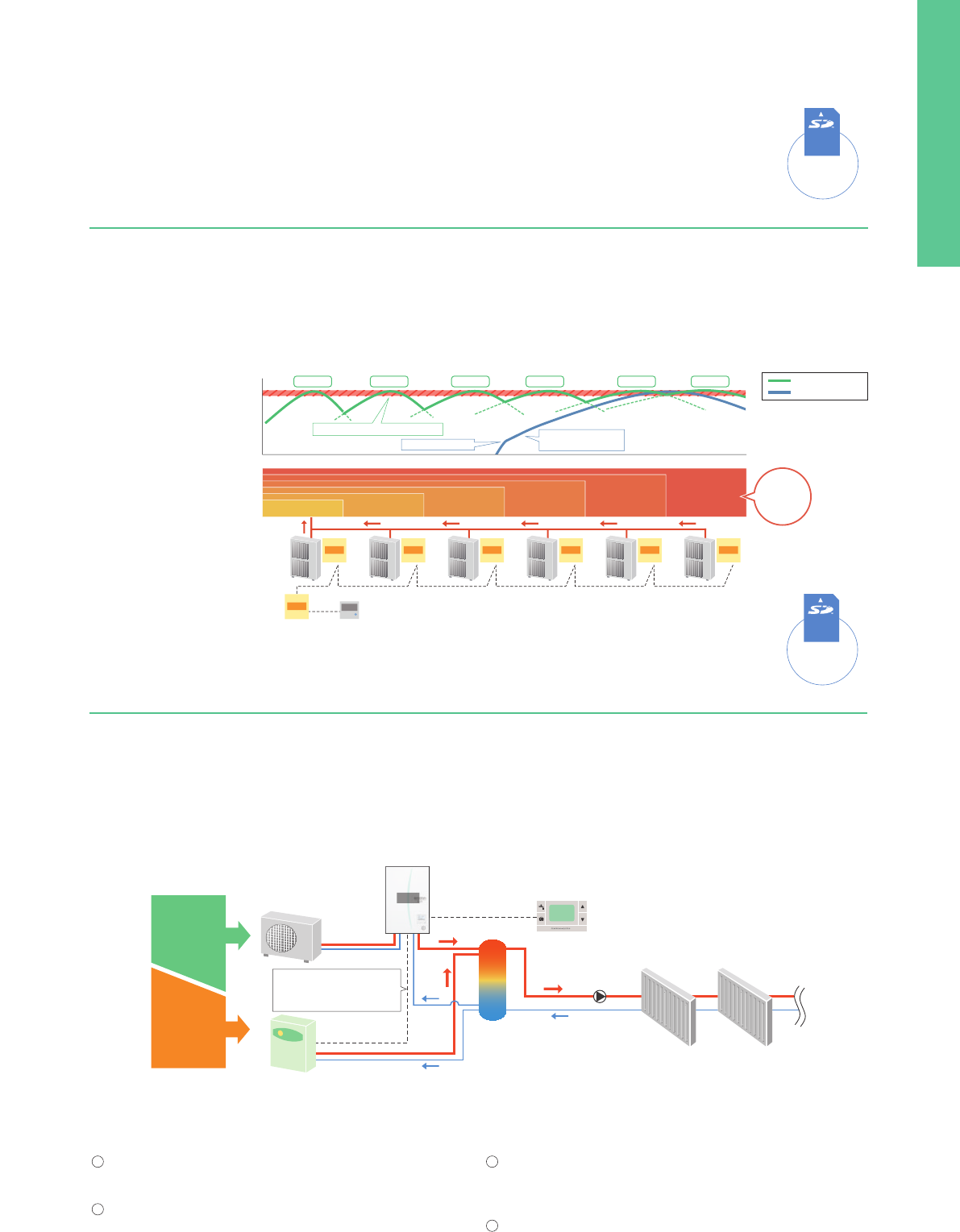
148
An existing boiler can be used for extra heating capacity in an efficient way
The flexibility of ECODAN’s intelligent control allows the system to be combined with the boiler currently in use. Additionally, this control can judge
which heating source to use either ECODAN or the existing boiler, based on various conditions*.
In the event of one heating unit not working due to some unforeseen problem, the other heating system can be used as a back-up, thereby
preventing the heating system operation from stopping completely.
*Please check below “Heat source switchover”.
Connect up to 6 units – Automatic control of multiple units
for bigger capacity and better efficiency
A maximum of 6 units* can be configured according to the heating/cooling load of the building. The most efficient number of operating units is
determined automatically based on heating/cooling load. This enables ECODAN to provide optimal room temperature control, and thus superior
comfort for room occupants. Also incorporated is a rotation function that enables each unit to run for an equal time period.
If one of the units malfunctions when using the Multiple Unit Control, another unit can be automatically operated for back-up, thereby preventing
the system operation from stopping completely.
*Only same models (same capacity) can be used.
Intelligent system combining a boiler with ECODAN
Intelligent boiler interlock
Multiple unit control
■ Multiple unit control
■ Intelligent boiler interlock systen
Settings can be
performed using
an SD card.
*SD logo is a trademark
of SD-3C, LLC
Settings can be
performed using
an SD card.
*SD logo is a trademark
of SD-3C, LLC
*Items such as mixing tank, mixing valve flow switch and pumps are not included and need to be purchased locally.
Wireless remote controller
as thermistor
Radiator
Mixing control
Mixing tank
Hydro Box
FTC
Pump
Pump
Mixing
valve
40°C
30°C
Underfloor heating
Flow Switch
Flow Switch
Maximize energy savings while retaining comfort at all times
Settings can be
performed using
an SD card.
*SD logo is a trademark
of SD-3C, LLC
Auto Adaptation
Regarding the relation of flow temperature and unit performance, a 1°C drop
in the flow temperature improves the coefficient of performance (COP) of the
ATW system by 2%. This means that energy savings are dramatically affected
by controlling the flow temperature in the system.
In a conventional system controller, the flow temperature is determined based
on the pre-set heat curve depending on the actual outdoor temperature. How-
ever, this requires a complicated setting to achieve the optimal heat curve.
Flow temp.
Outdoor temp.
COP is
improved 2%
If flow
temperature is
lowered 1°C
60°C
30°C
-15°C 10°C
(c) Lower than the target room temp.
Room temp.
Target temp.
Time
(b) Approximately same as the target temp.
(a) Higher than the target room temp.
Future
3 points
lower the flow temp.
keep the flow temp.
raise the flow temp.
Modify the flow temperature by comparing
actual and estimated room temperature.
T0 T1 Current
Aiming to realise further comfort and energy savings, Mitsubishi Electric is proud to introduce a revolutionary new controller. Our advanced Auto
Adaptation function measures the room temperature and outdoor temperature, and then calculates the required heating capacity for the room.
Simply stated, the flow temperature is automatically controlled according to the required heating capacity, while optimal room temperature is
maintained at all times, ensuring the appropriate heating capacity and preventing energy from being wasted. Furthermore, by estimating future
changes in room temperature, the system works to prevent unnecessary increases and decreases in the flow temperature.
Accordingly, Auto Adaptation maximises both comfort and energy savings without the need for complicated settings.
Mitsubishi Electric’s Auto Adaptation function automatically tracks changes in the actual room temperature
and outdoor temperature and adjusts the flow temperature accordingly.
■ Future room temperature estimation
■ Heat curve setting (Example)
Unique technology of ECODAN
Simultaneously control two different zones
Two-zone control (for heating/cooling)
■ Two temperature zones
Using ECODAN, it is possible to control two different flow temperatures, thereby managing two different heating load requirements. The system
can adjust and maintain two flow temperatures when different temperatures are required for different rooms; for example, controlling a flow
temperature of 40°C for the bedroom radiators and another flow temperature of 30°C for the living room floor heating.
Another feature of this model is that two-zone cooling control is now possible. Using these functions it is easy to maintain the most comfortable
temperature in each room and to save energy too.
Settings can be
performed using
an SD card.
*SD logo is a trademark
of SD-3C, LLC
Multiple unit control
Main RC
FTC
slave
23kW
+
23kW
+
23kW
+
23kW
+
23kW
+
23kW
FTC
slave
FTC
slave
FTC
slave
FTC
slave
FTC
slave
COP ratio (%)
Total Capacity
100
Multiple unit control
One large unit control
Always high efficient operation !
Inefficient operation
at low capacity.
ON/OFF control
1 unit
2 units
3 units
4 units
5 units
6 units
master
FTC
138
kW
!!
Up to
* Items such as a mixing tank, and pump are not included and need to be purchased locally.
Room temperature
wireless remote controller (option)
Pump
Radiator
Electricity
Other source
(Gas, Oil, etc)
Boiler
Turning boiler on/off
according to operational
conditions.
Mixing tank
Radiator
* Thermostat (field supply) also can be used.
Switchover based on actual outdoor temperature
• Heat source switchover occurs when the outdoor temperature
drops below a pre-set temperature.
Switchover based on running cost
• Heat source switchover occurs by judging optimal operation
based on running cost.
*Pre-registration of the energy price of electricity,
and gas or oil per 1kWh is necessary.
Heat source switchover - Choose appropriate system based on needs
4 types of heat source switchover logic
FTC
Hydro box
1
2
Switchover based on CO2 emission level
• Heat source switchover occurs to minimise CO
2 emission.
*Pre-registration of CO
2 emission amount from electricity and gas
or oil is necessary.
Switchover can also be activated via external input
• For example, the peak cut signal from electric power company.
3
4
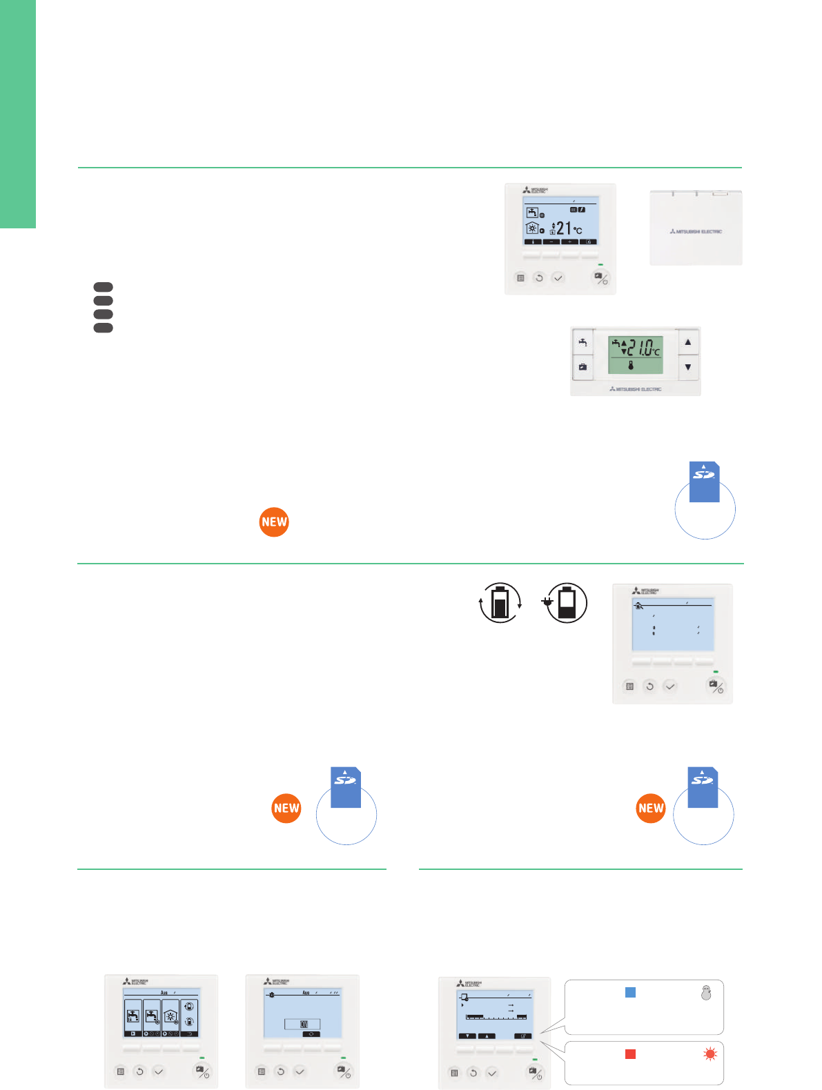
149
Pump for primary water circuit* speed setting possible using ECODAN’s main remote controller
Easy commissioning
Smart user-friendly controller with stylish design
Remote controllers
View electricity consumption and heat output on the remote controller
Energy monitoring
CONSUMED ELECTRICAL ENERGY
2 23
:
592015
–DHW
–Heatin
–Coolin
2015 57kW
7kW
50kW
0kW
57kW
7kW
50kW
0kW
Jan
Jan
Jan
Jan
CONSUMED ELECTRICAL ENERGY
2 23
:
592015
–DHW
–Heatin
–Coolin
2015
13 Jun 13
:
412015
13 Jun 13
:
412015
Flow sensor newly incorporated
The flow sensor is key for monitoring energy output and can also be used to detect flow error as well.
– Flow rate can be checked on the main remote controller.
– Flow rate can also be shown as graphs using the SD card tool.
Run indoor unit* without outdoor unit
During installation or situations such as an outdoor unit malfunction, the indoor unit can be operated using a heater.
While using this mode, flow and tank temperature are selectable.
Fixing and maintenance of the outdoor unit can be done without stopping heating and domestic hot water operation*.
*Models with electric heater only.
*When the indoor unit operation stops, please check all settings after the outdoor unit is connected.
Other features
– Daily, monthly and yearly data are stored and can be displayed using the main
remote controller.
– External power meter and heat meter can be connected for accurate measurement.
– SD card is also available for storing data.
*Using pre-set values on the main remote controller, estimated energy consumption/output can be shown without external power
and a heat meter.
Depending on operating condition and system configuration, there is some possibility to show different data from the reality.
*This function is available depending on the version of the outdoor unit model.
PAR-WT50R-E (Option)
Wireless remote controller
Main controller
PAR-WR51R-E (Option)
Receiver
Heating capacity
produced
Electric energy
used
Main remote controller
• Large screen and backlight for excellent visibility, even in dark environment
• Multi-language support (supports 15 languages)
• Can be removed from main unit and installed in a remote location (up to 500m)
• Quick reading of operation data (7.5 times faster than previous model)
• Wide range of convenient functions in response to user demand
Function settings
– Energy monitoring
– Two-zone control (cooling and heating)
– Two separate schedules
– Summer time setting
– Built-in room temperature sensors
– Hybrid control (boiler interlock)
Items that can be pre-set
Simply copying pre-set data to an SD card,
the same settings can input into another unit using the SD card.
• Initial settings (time display, contact number, etc.)
• Heating settings
– Auto adaptation
– Heat curve
– Two different temperature zones (heating and cooling)
• Interlocked boiler operation settings
• Holiday mode settings
• Schedule timer settings (two separate schedules)
• Domestic hot water settings
• Legionella prevention settings
All items that are set by the main controller can be set via a personal
computer.
Data that can be stored
Operation data up to a month long can be stored on a single
SD card (2GB).
• Consumed electrical energy
• Delivered energy
• Flow rate
• Operation time
• Defrost time
• Actual temperature
– Room temperature
– Flow temperature
– Return temperature
– Domestic hot water temperature
– Outdoor temperature
• Error record
• Input signal
• Etc.
NEW
NEW
NEW
NEW
Every end user can now easily check the
energy data of the ECODAN heat pump.
Settings can be
performed using
an SD card.
For easier settings and data logging
SD* card
The initial setting for ECODAN is now simpler than ever
before. The special software enables the required initial
settings to be saved to an SD card using a personal
computer. The system set-up is as easy as moving the SD
card from the computer to the SD card slot in the indoor
unit. Compared to the previous procedure of inputting
settings using the main controller at the installation site,
a remarkable reduction in set-up time has been achieved.
Thus, it is ideal for busy installers.
*SD card function is only used at the time of installation.
Settings can be
performed using
an SD card.
*SD logo is a trademark
of SD-3C, LLC
*SD logo is a trademark
of SD-3C, LLC
Easy adjustment for
summer time
Summer time setting
Just switch the summer time mode ‘on’ using the main remote
controller and the clock in the main remote controller is adjusted to
summer time hours.
This function can release the end user from clock setting tasks.
Settings can be
performed using
an SD card.
*SD logo is a trademark
of SD-3C, LLC
Two separate schedules
Two different schedule settings are available for use via the main
remote controller.
These schedules can be pre-set and changed depending on the season.
For example, from November to March, space heating and domestic
hot water are used; however, during warm months such as from April
to October, only domestic hot water is used.
Settings can be
performed using
an SD card.
*SD logo is a trademark
of SD-3C, LLC
– Floor drying mode
– Weekly timer
– Holiday mode
– Legionella prevention
– Error codes
29 2015 23
:
59
6kWh
15kWh
29 2015 23
:
59
6kWh
15kWh
30
Summer time
2015 0
:
00
30
Summer time
2015 0
:
00
Schedule timer 1 Apr Oct
Schedule timer 2 Nov Mar
Jan Dec
1 Sep 12
:
302015
7
Schedule timer 1 Apr Oct
Schedule timer 2 Nov Mar
Jan Dec
1 Sep 12
:
302015
7
Schedule 1
daytime
early morning
any time
Space heating
Domestic hot water
Winter time
Schedule 2
Domestic hot water
Summer time
<
Example
>
Pre-setting two different schedules
for winter and summer seasons
Wireless remote controller (optional)
• Built-in room temperature sensor; easy to place in the best position to detect room temperature
• Wiring work eliminated
• Simple design that is easy to operate
• Remote control from any room without needing to choose an installation location
• Backlight and big buttons that are easy to operate
• Domestic hot water boost and cancellation
• Simplified holiday mode
Hydro box operation panel
Printed circuit board
Control and electric box
SD card slot SD card
SD card
Settings can be performed easily
and the logging of operation data saved
to an SD card can be confirmed via
a personal computer.
Even when the system is running, pump output can be set to one of five different settings using
the main remote controller.
The person commissioning the system can adjust this speed much more easily.
*Speed setting of pump for domestic hot water is not available through the main remote controller
when the system is running.
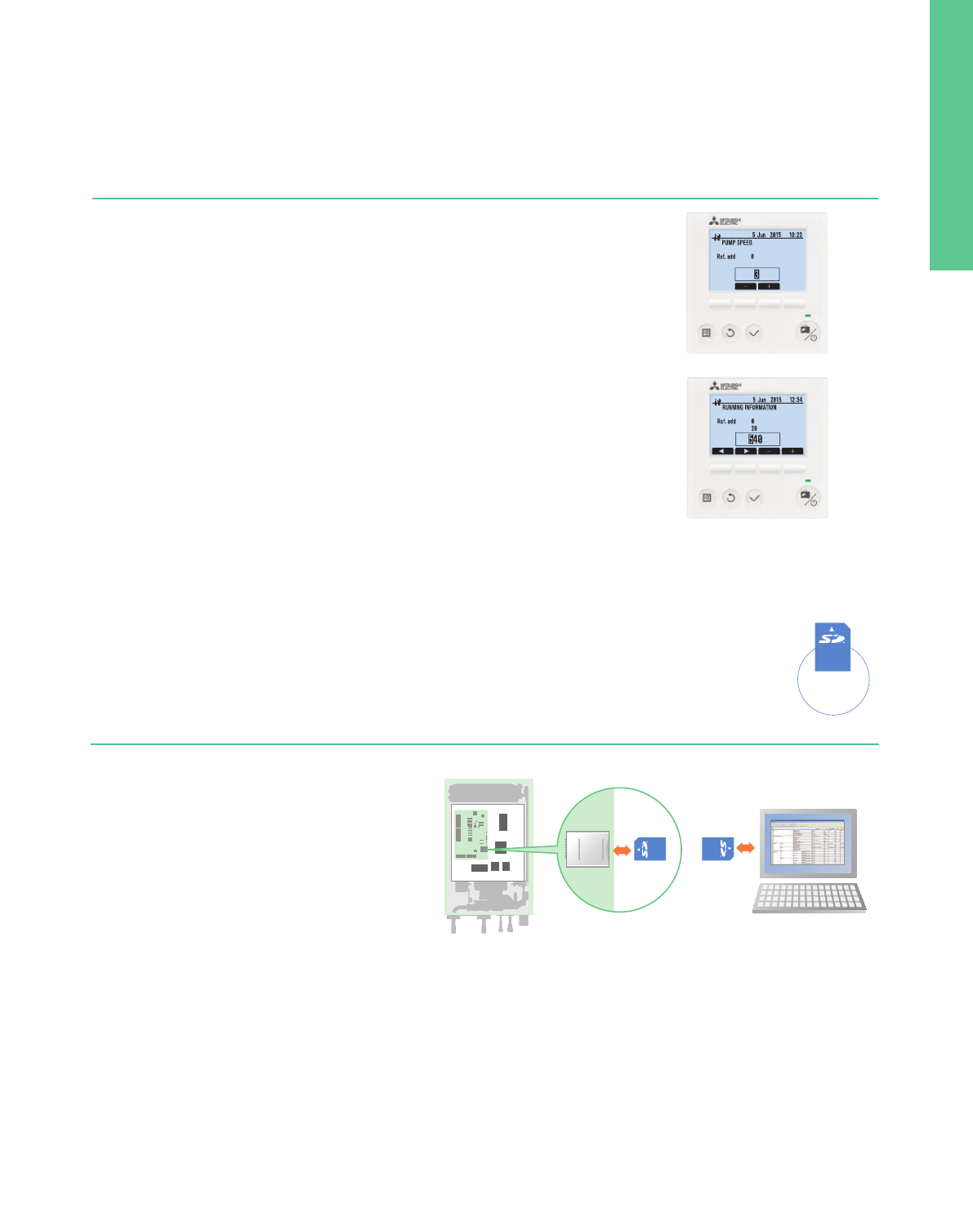
150
Pump for primary water circuit* speed setting possible using ECODAN’s main remote controller
Easy commissioning
Smart user-friendly controller with stylish design
Remote controllers
View electricity consumption and heat output on the remote controller
Energy monitoring
CONSUMED ELECTRICAL ENERGY
2 23
:
592015
–DHW
–Heatin
–Coolin
2015 57kW
7kW
50kW
0kW
57kW
7kW
50kW
0kW
Jan
Jan
Jan
Jan
CONSUMED ELECTRICAL ENERGY
2 23
:
592015
–DHW
–Heatin
–Coolin
2015
13 Jun 13
:
412015
13 Jun 13
:
412015
Flow sensor newly incorporated
The flow sensor is key for monitoring energy output and can also be used to detect flow error as well.
– Flow rate can be checked on the main remote controller.
– Flow rate can also be shown as graphs using the SD card tool.
Run indoor unit* without outdoor unit
During installation or situations such as an outdoor unit malfunction, the indoor unit can be operated using a heater.
While using this mode, flow and tank temperature are selectable.
Fixing and maintenance of the outdoor unit can be done without stopping heating and domestic hot water operation*.
*Models with electric heater only.
*When the indoor unit operation stops, please check all settings after the outdoor unit is connected.
Other features
– Daily, monthly and yearly data are stored and can be displayed using the main
remote controller.
– External power meter and heat meter can be connected for accurate measurement.
– SD card is also available for storing data.
*Using pre-set values on the main remote controller, estimated energy consumption/output can be shown without external power
and a heat meter.
Depending on operating condition and system configuration, there is some possibility to show different data from the reality.
*This function is available depending on the version of the outdoor unit model.
PAR-WT50R-E (Option)
Wireless remote controller
Main controller
PAR-WR51R-E (Option)
Receiver
Heating capacity
produced
Electric energy
used
Main remote controller
• Large screen and backlight for excellent visibility, even in dark environment
• Multi-language support (supports 15 languages)
• Can be removed from main unit and installed in a remote location (up to 500m)
• Quick reading of operation data (7.5 times faster than previous model)
• Wide range of convenient functions in response to user demand
Function settings
– Energy monitoring
– Two-zone control (cooling and heating)
– Two separate schedules
– Summer time setting
– Built-in room temperature sensors
– Hybrid control (boiler interlock)
Items that can be pre-set
Simply copying pre-set data to an SD card,
the same settings can input into another unit using the SD card.
• Initial settings (time display, contact number, etc.)
• Heating settings
– Auto adaptation
– Heat curve
– Two different temperature zones (heating and cooling)
• Interlocked boiler operation settings
• Holiday mode settings
• Schedule timer settings (two separate schedules)
• Domestic hot water settings
• Legionella prevention settings
All items that are set by the main controller can be set via a personal
computer.
Data that can be stored
Operation data up to a month long can be stored on a single
SD card (2GB).
• Consumed electrical energy
• Delivered energy
• Flow rate
• Operation time
• Defrost time
• Actual temperature
– Room temperature
– Flow temperature
– Return temperature
– Domestic hot water temperature
– Outdoor temperature
• Error record
• Input signal
• Etc.
NEW
NEW
NEW
NEW
Every end user can now easily check the
energy data of the ECODAN heat pump.
Settings can be
performed using
an SD card.
For easier settings and data logging
SD* card
The initial setting for ECODAN is now simpler than ever
before. The special software enables the required initial
settings to be saved to an SD card using a personal
computer. The system set-up is as easy as moving the SD
card from the computer to the SD card slot in the indoor
unit. Compared to the previous procedure of inputting
settings using the main controller at the installation site,
a remarkable reduction in set-up time has been achieved.
Thus, it is ideal for busy installers.
*SD card function is only used at the time of installation.
Settings can be
performed using
an SD card.
*SD logo is a trademark
of SD-3C, LLC
*SD logo is a trademark
of SD-3C, LLC
Easy adjustment for
summer time
Summer time setting
Just switch the summer time mode ‘on’ using the main remote
controller and the clock in the main remote controller is adjusted to
summer time hours.
This function can release the end user from clock setting tasks.
Settings can be
performed using
an SD card.
*SD logo is a trademark
of SD-3C, LLC
Two separate schedules
Two different schedule settings are available for use via the main
remote controller.
These schedules can be pre-set and changed depending on the season.
For example, from November to March, space heating and domestic
hot water are used; however, during warm months such as from April
to October, only domestic hot water is used.
Settings can be
performed using
an SD card.
*SD logo is a trademark
of SD-3C, LLC
– Floor drying mode
– Weekly timer
– Holiday mode
– Legionella prevention
– Error codes
29 2015 23
:
59
6kWh
15kWh
29 2015 23
:
59
6kWh
15kWh
30
Summer time
2015 0
:
00
30
Summer time
2015 0
:
00
Schedule timer 1 Apr Oct
Schedule timer 2 Nov Mar
Jan Dec
1 Sep 12
:
302015
7
Schedule timer 1 Apr Oct
Schedule timer 2 Nov Mar
Jan Dec
1 Sep 12
:
302015
7
Schedule 1
daytime
early morning
any time
Space heating
Domestic hot water
Winter time
Schedule 2
Domestic hot water
Summer time
<
Example
>
Pre-setting two different schedules
for winter and summer seasons
Wireless remote controller (optional)
• Built-in room temperature sensor; easy to place in the best position to detect room temperature
• Wiring work eliminated
• Simple design that is easy to operate
• Remote control from any room without needing to choose an installation location
• Backlight and big buttons that are easy to operate
• Domestic hot water boost and cancellation
• Simplified holiday mode
Hydro box operation panel
Printed circuit board
Control and electric box
SD card slot SD card
SD card
Settings can be performed easily
and the logging of operation data saved
to an SD card can be confirmed via
a personal computer.
Even when the system is running, pump output can be set to one of five different settings using
the main remote controller.
The person commissioning the system can adjust this speed much more easily.
*Speed setting of pump for domestic hot water is not available through the main remote controller
when the system is running.
151
Split type specifications
<Cylinder unit>
Model name
Dimensions
Weight (empty)
Power supply (V / Phase / Hz)
Heater
Domestic
hot water tank
Guaranteed
operating
range
*
1
Target
temperature
range
Sound pressure level (SPL)
Booster
heater
Immersion
heater
Volume / Material
Heating
Outdoor
Ambient
DHW
Legionella prevention
Type
Immersion heater
Expansion vessel
Booster heater
H×W×D
Power supply (V / Phase / Hz)
Capacity
Current
Breaker size
Power supply (V / Phase / Hz)
Capacity
Current
Breaker size
Room temperature
Cooling
Heating
Flow temperature
Indoor unit
*1 The environment must be frost-free *2 UK model
*1 The environment must be frost-free
mm
kg
kW
A
A
kW
A
A
L / –
°C
°C
°C
°C
°C
°C
°C
dB (A)
<Hydro box>
Model name EHSD-
MEC
–
–
–
–
×
×
–
–
–
–
×
×
–
–
×
–
×
×
–
–
×
800×530×360 950×600×360
44
230/Single/50
400/Three/50
230/Three/50
230/Single/50–
230/Single/50 400/Three/50
–
– 2 – 2 2 6 (2/4/6) 6 (2/4/6) 9 (3/6/9) 9 (3/6/9) 9 (3/6/9)
– 9 – 9 9 26 26 13 13 23
– 16 – 16 16 32 32 16 16 32
–
–
–
–
See outdoor unit spec table
25~60
–
–
–
28 30
49 44 49494348424438
EHSD-
MC
–
×
–
–
–
–
–
43
–
×
×
–
–
×
–
×
×
EHSD-
VM2C
–
×
×
9 (3/6/9)
13
16
45
EHSD-
YM9C
Heating only
EHSC-
MEC
EHSC-
VM2C
EHSC-
VM2EC
EHSC-
VM6C
EHSC-
VM6EC
EHSC-
YM9C
EHSC-
YM9EC
EHSC-
TM9C
400/Three/50
9 (3/6/9)
13
16
62
–
–
×
EHSE-
YM9EC
60
–
–
–
EHSE-
MEC
Dimensions
Weight (empty)
Power supply (V / Phase / Hz)
Heater
Guaranteed
operating
range
*
1
Target
temperature
range
Sound pressure level (SPL)
Booster
heater
Ambient
Outdoor
Heating
Type
Immersion heater
Expansion vessel
Booster heater
H×W×D
Power supply (V / Phase / Hz)
Capacity
Current
Breaker size
Heating
Cooling
Room temperature
Flow temperature
Cooling Room temperature
Flow temperature
mm
kg
kW
A
A
°C
°C
°C
°C
°C
°C
°C
dB (A)
EHST20C-
VM2C
EHST20C-
VM6C
EHST20C-
YM9C
EHST20C-
TM9C
EHST20C-
VM2EC
EHST20C-
VM6EC
EHST20C-
YM9EC
EHST20C-
MEC
EHST20D-
VM2C
EHST20D-
MEC
EHST20D-
MHC
EHST20C-
MHCW
*
2
EHST20D-
MHCW
*
2
Heating only
–
×
×
–
×
×
–
×
×
–
×
×
–
–
×
–
–
×
–
–
×
–
–
–
–
×
×
–
–
–
×
×
–
×
×
–
×
×
–
1600×595×680
110 111 112 112 104 105 106 103 103 96103 110 103
230/Single/50
230/Single/50
230/Single/50
400/Three/50 400/Three/50230/Three/50
230/Single/50 ––
–
–
–
–
–
–
2 6 (2/4/6) 9 (3/6/9) 9 (3/6/9) 2 6 (2/4/6) 2
9 26 13 23 9 26 9
16 32 16 32 16 32
9 (3/6/9)
13
16
EHST20D-
YM9C
–
×
×
105
400/Three/50
9 (3/6/9)
13
1616
EHST20D-
VM2EC
–
–
×
97
230/Single/50
2
9
16
– 230/Single/50
230/Single/50
– 3
– 13
–
–
–
–
– 16
3
13
16
200 / Stainless steel
See outdoor unit spec table
–
10~30
25~60
Cooling Room temperature
Flow temperature
°C
°C
–
–
40~60
60~70
28
0~35
*
1
<Reversible cylinder unit>
Model name
Dimensions
Weight (empty)
Power supply (V / Phase / Hz)
Heater
Domestic
hot water tank
Guaranteed
operating
range
*
1
Target
temperature
range
Sound pressure level (SPL)
Booster
heater
Immersion
heater
Volume / Material
Heating
Outdoor
Ambient
DHW
Legionella prevention
Type
Immersion heater
Expansion vessel
Booster heater
H×W×D
Power supply (V / Phase / Hz)
Capacity
Current
Breaker size
Power supply (V / Phase / Hz)
Capacity
Current
Breaker size
Room temperature
Cooling
Heating
Flow temperature
*1 The environment must be frost-free
*2 If you use our system in cooling mode at the low ambient temperature (10°C or below),
there are some risks of plate heat exchanger breaking by frozen water.
mm
kg
kW
A
A
kW
A
A
L / –
°C
°C
°C
°C
°C
°C
°C
dB (A)
Heating and cooling
1600×595×680
230/Single/50
103
ERST20D-
VM2C
–
×
×
230/Single/50
2
9
16
–
–
–
–
96
ERST20D-
MEC
–
–
–
–
–
–
–
–
–
–
–
103
ERST20C-
MEC
–
–
–
–
–
–
–
–
–
–
–
110
ERST20C-
VM2C
–
×
×
230/Single/50
2
9
16
–
–
–
–
200 / Stainless steel
See outdoor unit spec table
See outdoor unit spec table (minimum 10°C*
2
)
10~30
25~60
Cooling Room temperature
Flow temperature
°C
°C
–
5~25
40~60
60~70
28
0~35
*
1
10~30
0~35
*
1
*1 The environment must be frost-free
*2 If you use our system in cooling mode at the low ambient temperature (10°C or below),
there are some risks of plate heat exchanger breaking by frozen water.
<Reversible hydro box>
Model name
950×600×360800×530×360
230/Single/50
See outdoor unit spec table
25~60
–
5~25
28 30
230/Single/50
2
9
16
45
–
×
×
ERSD-
VM2C
–
–
–
–
43
–
–
–
ERSC-
MEC
–
–
–
–
61
–
–
–
ERSE-
MEC
Heating and cooling
230/Single/50
2
9
16
49
–
×
×
ERSC-
VM2C
400/Three/50
9 (3/6/9)
13
16
63
–
–
×
ERSE-
YM9EC
Dimensions
Weight (empty)
Power supply (V / Phase / Hz)
Heater
Guaranteed
operating
range
*
1
Target
temperature
range
Sound pressure level (SPL)
Booster
heater
Ambient
Outdoor
Heating
Type
Immersion heater
Expansion vessel
Booster heater
H×W×D
Power supply (V / Phase / Hz)
Capacity
Current
Breaker size
Heating
Cooling
Room temperature
Flow temperature
Cooling Room temperature
Flow temperature
mm
kg
kW
A
A
°C
°C
°C
°C
°C
°C
°C
dB (A)
10~30
0~35
*
1
See outdoor unit spec table (minimum 10°C*
2
)
<Outdoor unit>
Parts name Model name
Power Inverter
Eco
Inverter
ZUBADAN
SUHZ-
SW45VA (H)
–
–
×
–
–
–
–
–
–
–
–
–
–
–
–
PUHZ-
SW50VKA (-BS)
–
×
–
×
–
–
×
–
–
–
×
×
–
–
×
PUHZ-
SW75VHA (-BS)
×
–
–
–
×
–
–
×
–
×
–
–
×
–
×
PUHZ-
SW100V/YHA (-BS)
×
–
–
–
×
–
–
×
–
×
–
–
×
–
×
PUHZ-
SW120V/YHA (-BS)
×
–
–
–
×
–
–
×
–
×
–
–
×
–
×
PUHZ-
SHW80VHA
×
–
–
–
×
–
–
×
–
–
–
–
–
–
×
PUHZ-
SHW112V/YHA
×
–
–
–
×
–
–
×
–
–
–
–
–
–
×
PUHZ-
SHW140YHA
×
–
–
–
×
–
–
×
–
–
–
–
–
–
×
PUHZ-
SW160YKA (-BS)
×
–
–
–
–
×
–
–
×
×
–
–
–
×
×
PUHZ-
SW200YKA (-BS)
×
–
–
–
–
×
–
–
×
×
–
–
–
×
×
PUHZ-
SHW230YKA2
×
–
–
–
–
×
–
–
×
–
–
–
–
–
×
Connector for drain hose heater
signal output
Air discharge guide
Air protection guide
Drain socket
Centralised drain pan
Control / Service tool
PAC-SE60RA-E
PAC-SE61RA-E
MAC-886SG-E
PAC-SJ07SG-E
PAC-SG59SG-E
PAC-SG96SG-E
PAC-SJ06AG-E
PAC-SH63AG-E
PAC-SH95AG-E
PAC-SG61DS-E
PAC-SJ08DS-E
PAC-SG63DP-E
PAC-SG64DP-E
PAC-SH97DP-E
PAC-SK52ST
H×W×DDimensions
Product weight (empty)
Power supply (V / Phase / Hz)
Heating
(A7/W35)
Heating
(A2/W35)
Cooling
(A35/W7)
Cooling
(A35/W18)
Sound pressure
level (SPL)
Sound power
level (PWL)
Operating current (max)
Breaker size
Piping
Guaranteed
operating
range
SUHZ-
SW45VA (H)
*
1
880×840×330
54
4.50
5.06
0.889
3.50
3.40/3.04
1.029/1.151
4.00
2.73
1.465
3.80
4.28
0.888
52
61
12.0
20
6.35/12.7
30
30
–15 to +24
–15 to +35
–10 to +46
PUHZ-
SW50VKA (-BS)
630×809×300
43
5.50
4.42
1.244
5.00
2.97
1.684
4.50
2.76
1.630
5.00
4.60
1.087
46
63
13.0
16
6.35/12.7
40
30
–15 to +21
–15 to +35
–15 to +46
PUHZ-
SW75VHA (-BS)
943×950×330
75
8.00
4.40
1.818
7.50
3.40
2.206
6.60
2.82
2.340
7.10
4.43
1.603
51
68
17.0
25
9.52/15.88
40
30
–20 to +21
–20 to +35
–15 to +46
PUHZ-
SW100V/YHA (-BS)
1350×950×330
118/130
11.20
4.45
2.517
10.00
3.32
3.009
9.10
2.75
3.309
10.00
4.35
2.299
54
70
29.5/13.0
32/16
9.52/15.88
75
30
–20 to +21
–20 to +35
–15 to +46
PUHZ-
SW120V/YHA (-BS)
1350×950×330
118/130
16.00
4.10
3.902
12.00
3.24
3.704
12.50
2.32
5.388
14.00
4.08
3.431
54
72
29.5/13.0
32/16
9.52/15.88
75
30
–20 to +21
–20 to +35
–15 to +46
PUHZ-
SW160YKA (-BS)
1338×1050×330
136
22.00
4.20
5.238
16.00
3.11
5.145
16.00
2.76
5.797
18.00
4.56
3.947
62
78
19.0
25
9.52/25.4
80
30
–20 to +21
–20 to +35
–15 to +46
PUHZ-
SW200YKA (-BS)
1338×1050×330
136
25.00
4.00
6.250
20.00
2.80
7.143
20.00
2.25
8.889
22.00
4.10
5.366
62
78
21.0
32
12.7/25.4
80
30
–20 to +21
–20 to +35
–15 to +46
PUHZ-
SHW80VHA
1350×950×330
120
8.00
4.65
1.720
8.00
3.55
2.254
7.10
3.31
2.145
7.10
4.52
1.571
51
69
29.5
32
9.52/15.88
75
30
–28 to +21
–28 to +35
–15 to +46
PUHZ-
SHW112V/YHA
1350×950×330
120/134
11.20
4.46
2.511
11.20
3.34
3.353
10.00
2.83
3.534
10.00
4.74
2.110
52
70
35.0/13.0
40/16
9.52/15.88
75
30
–28 to +21
–28 to +35
–15 to +46
PUHZ-
SHW140YHA
1350×950×330
134
14.00
4.22
3.318
14.00
2.96
4.730
12.50
2.17
5.760
12.50
4.26
2.934
52
70
13.0
16
9.52/15.88
75
30
–28 to +21
–28 to +35
–15 to +46
PUHZ-
SHW230YKA2
1338×1050×330
149
23.00
3.65
6.301
23.00
2.37
9.705
20.00
2.22
9.009
20.00
3.55
5.634
59
75
26.0
32
12.7/25.4
80
30
–25 to +21
–25 to +35
–15 to +46
VHA : 230/Single/50 YHA, YKA : 400/Three/50
mm
kg
kW
kW
kW
kW
kW
kW
kW
kW
dB (A)
dB (A)
A
A
mm
m
m
°C
°C
°C
Capacity
COP
Power input
Capacity
COP
Power input
Capacity
EER
Power input
Capacity
EER
Power input
Heating
Heating
Diameter
Max. length
Max. height
Heating
DHW
Cooling
*
2
Outdoor unit
Model name
Liquid/Gas
Out-In
Out-In
Note: based on EN 14511 (Input to circulation pump is not included.) It may differ according to the system configuration.
*1 SUHZ-SW45VAH incorporates base heater.
*2 Optional air protection guide is required where ambient temperature is lower than –5°C.
<Indoor unit>
Parts name Model name Specification Cylinder unit Hydro box
Wirelss remote
controller
Wirelss receiver
Thermistors
EHPT accessories
for UK
Immersion heater
Wi-Fi interface
Drain pan stand
PAR-WT50R-E
PAR-WR51R-E
PAC-SE41TS-E
PAC-TH011-E
PAC-TH011TK-E
PAC-TH011TKL-E
PAC-TH011HT-E
PAC-I03V2-E
PAC-WK01UK-E
PAC-WF010-E
PAC-DP01-E
Optional parts
For room temp.
For buffer and zone
(flow and return temp.)
For tank temp. (5m)
For tank temp. (30m)
For boiler
(flow and return temp.)
D665mm H270mm W595mm
N/W: 14.5kg
1Ph 3kW
Joint pipe
PAC-SG73RJ-E
For PUHZ-SW200YKA/
SHW230YKA2 (-BS)
ø9.52
ø12.7
*1 PAC-DP01-E is necessary when you use ERST units. If you use ERST units without this parts, drain will be flowed from the base of units, in cooling mode.
EHST20C-
VM2C
×
×
×
×
×
×
×
×
×
–
–
–
×
×
×
×
×
×
×
×
×
–
–
EHST20C-
VM6C
–
×
×
×
×
×
×
×
×
×
–
–
EHST20C-
YM9C
–
×
×
×
×
×
×
×
×
×
–
–
EHST20C-
TM9C
–
×
×
×
×
×
×
×
×
×
–
–
EHST20C-
VM2EC
–
×
×
×
×
×
–
–
×
×
–
–
EHST20C-
VM6EC
–
×
×
×
×
×
–
–
×
×
–
–
EHST20C-
YM9EC
–
×
×
×
×
×
–
–
×
×
–
–
EHST20C-
MEC
–
×
×
×
×
×
–
–
×
×
–
–
EHST20D-
VM2C
–
×
×
×
×
×
–
–
×
–
–
–
EHST20D-
MHC
–
×
×
×
×
×
–
–
×
×
–
–
EHST20D-
MEC
–
×
×
×
×
×
–
–
×
–
×
–
EHST20C-
MHCW
–
×
×
×
×
×
–
–
×
–
×
–
EHST20D-
MHCW
–
×
×
×
×
×
–
–
×
×
–
–
EHST20D-
YM9C
–
×
×
×
×
×
–
–
×
×
–
–
EHST20D-
VM2EC
–
E✽SE
models
×
×
×
×
×
×
×
×
–
–
–
×
E✽SD or E✽SC
models
×
×
×
×
×
×
×
×
–
–
–
––
×
×
×
×
×
–
–
×
×
–
ERST
models
×
*
1
152
Split type specifications
<Cylinder unit>
Model name
Dimensions
Weight (empty)
Power supply (V / Phase / Hz)
Heater
Domestic
hot water tank
Guaranteed
operating
range
*
1
Target
temperature
range
Sound pressure level (SPL)
Booster
heater
Immersion
heater
Volume / Material
Heating
Outdoor
Ambient
DHW
Legionella prevention
Type
Immersion heater
Expansion vessel
Booster heater
H×W×D
Power supply (V / Phase / Hz)
Capacity
Current
Breaker size
Power supply (V / Phase / Hz)
Capacity
Current
Breaker size
Room temperature
Cooling
Heating
Flow temperature
Indoor unit
*1 The environment must be frost-free *2 UK model
*1 The environment must be frost-free
mm
kg
kW
A
A
kW
A
A
L / –
°C
°C
°C
°C
°C
°C
°C
dB (A)
<Hydro box>
Model name EHSD-
MEC
–
–
–
–
×
×
–
–
–
–
×
×
–
–
×
–
×
×
–
–
×
800×530×360 950×600×360
44
230/Single/50
400/Three/50
230/Three/50
230/Single/50–
230/Single/50 400/Three/50
–
– 2 – 2 2 6 (2/4/6) 6 (2/4/6) 9 (3/6/9) 9 (3/6/9) 9 (3/6/9)
– 9 – 9 9 26 26 13 13 23
– 16 – 16 16 32 32 16 16 32
–
–
–
–
See outdoor unit spec table
25~60
–
–
–
28 30
49 44 49494348424438
EHSD-
MC
–
×
–
–
–
–
–
43
–
×
×
–
–
×
–
×
×
EHSD-
VM2C
–
×
×
9 (3/6/9)
13
16
45
EHSD-
YM9C
Heating only
EHSC-
MEC
EHSC-
VM2C
EHSC-
VM2EC
EHSC-
VM6C
EHSC-
VM6EC
EHSC-
YM9C
EHSC-
YM9EC
EHSC-
TM9C
400/Three/50
9 (3/6/9)
13
16
62
–
–
×
EHSE-
YM9EC
60
–
–
–
EHSE-
MEC
Dimensions
Weight (empty)
Power supply (V / Phase / Hz)
Heater
Guaranteed
operating
range
*
1
Target
temperature
range
Sound pressure level (SPL)
Booster
heater
Ambient
Outdoor
Heating
Type
Immersion heater
Expansion vessel
Booster heater
H×W×D
Power supply (V / Phase / Hz)
Capacity
Current
Breaker size
Heating
Cooling
Room temperature
Flow temperature
Cooling Room temperature
Flow temperature
mm
kg
kW
A
A
°C
°C
°C
°C
°C
°C
°C
dB (A)
EHST20C-
VM2C
EHST20C-
VM6C
EHST20C-
YM9C
EHST20C-
TM9C
EHST20C-
VM2EC
EHST20C-
VM6EC
EHST20C-
YM9EC
EHST20C-
MEC
EHST20D-
VM2C
EHST20D-
MEC
EHST20D-
MHC
EHST20C-
MHCW
*
2
EHST20D-
MHCW
*
2
Heating only
–
×
×
–
×
×
–
×
×
–
×
×
–
–
×
–
–
×
–
–
×
–
–
–
–
×
×
–
–
–
×
×
–
×
×
–
×
×
–
1600×595×680
110 111 112 112 104 105 106 103 103 96103 110 103
230/Single/50
230/Single/50
230/Single/50
400/Three/50 400/Three/50230/Three/50
230/Single/50 ––
–
–
–
–
–
–
2 6 (2/4/6) 9 (3/6/9) 9 (3/6/9) 2 6 (2/4/6) 2
9 26 13 23 9 26 9
16 32 16 32 16 32
9 (3/6/9)
13
16
EHST20D-
YM9C
–
×
×
105
400/Three/50
9 (3/6/9)
13
1616
EHST20D-
VM2EC
–
–
×
97
230/Single/50
2
9
16
– 230/Single/50
230/Single/50
– 3
– 13
–
–
–
–
– 16
3
13
16
200 / Stainless steel
See outdoor unit spec table
–
10~30
25~60
Cooling Room temperature
Flow temperature
°C
°C
–
–
40~60
60~70
28
0~35
*
1
<Reversible cylinder unit>
Model name
Dimensions
Weight (empty)
Power supply (V / Phase / Hz)
Heater
Domestic
hot water tank
Guaranteed
operating
range
*
1
Target
temperature
range
Sound pressure level (SPL)
Booster
heater
Immersion
heater
Volume / Material
Heating
Outdoor
Ambient
DHW
Legionella prevention
Type
Immersion heater
Expansion vessel
Booster heater
H×W×D
Power supply (V / Phase / Hz)
Capacity
Current
Breaker size
Power supply (V / Phase / Hz)
Capacity
Current
Breaker size
Room temperature
Cooling
Heating
Flow temperature
*1 The environment must be frost-free
*2 If you use our system in cooling mode at the low ambient temperature (10°C or below),
there are some risks of plate heat exchanger breaking by frozen water.
mm
kg
kW
A
A
kW
A
A
L / –
°C
°C
°C
°C
°C
°C
°C
dB (A)
Heating and cooling
1600×595×680
230/Single/50
103
ERST20D-
VM2C
–
×
×
230/Single/50
2
9
16
–
–
–
–
96
ERST20D-
MEC
–
–
–
–
–
–
–
–
–
–
–
103
ERST20C-
MEC
–
–
–
–
–
–
–
–
–
–
–
110
ERST20C-
VM2C
–
×
×
230/Single/50
2
9
16
–
–
–
–
200 / Stainless steel
See outdoor unit spec table
See outdoor unit spec table (minimum 10°C*
2
)
10~30
25~60
Cooling Room temperature
Flow temperature
°C
°C
–
5~25
40~60
60~70
28
0~35
*
1
10~30
0~35
*
1
*1 The environment must be frost-free
*2 If you use our system in cooling mode at the low ambient temperature (10°C or below),
there are some risks of plate heat exchanger breaking by frozen water.
<Reversible hydro box>
Model name
950×600×360800×530×360
230/Single/50
See outdoor unit spec table
25~60
–
5~25
28 30
230/Single/50
2
9
16
45
–
×
×
ERSD-
VM2C
–
–
–
–
43
–
–
–
ERSC-
MEC
–
–
–
–
61
–
–
–
ERSE-
MEC
Heating and cooling
230/Single/50
2
9
16
49
–
×
×
ERSC-
VM2C
400/Three/50
9 (3/6/9)
13
16
63
–
–
×
ERSE-
YM9EC
Dimensions
Weight (empty)
Power supply (V / Phase / Hz)
Heater
Guaranteed
operating
range
*
1
Target
temperature
range
Sound pressure level (SPL)
Booster
heater
Ambient
Outdoor
Heating
Type
Immersion heater
Expansion vessel
Booster heater
H×W×D
Power supply (V / Phase / Hz)
Capacity
Current
Breaker size
Heating
Cooling
Room temperature
Flow temperature
Cooling Room temperature
Flow temperature
mm
kg
kW
A
A
°C
°C
°C
°C
°C
°C
°C
dB (A)
10~30
0~35
*
1
See outdoor unit spec table (minimum 10°C*
2
)
<Outdoor unit>
Parts name Model name
Power Inverter
Eco
Inverter
ZUBADAN
SUHZ-
SW45VA (H)
–
–
×
–
–
–
–
–
–
–
–
–
–
–
–
PUHZ-
SW50VKA (-BS)
–
×
–
×
–
–
×
–
–
–
×
×
–
–
×
PUHZ-
SW75VHA (-BS)
×
–
–
–
×
–
–
×
–
×
–
–
×
–
×
PUHZ-
SW100V/YHA (-BS)
×
–
–
–
×
–
–
×
–
×
–
–
×
–
×
PUHZ-
SW120V/YHA (-BS)
×
–
–
–
×
–
–
×
–
×
–
–
×
–
×
PUHZ-
SHW80VHA
×
–
–
–
×
–
–
×
–
–
–
–
–
–
×
PUHZ-
SHW112V/YHA
×
–
–
–
×
–
–
×
–
–
–
–
–
–
×
PUHZ-
SHW140YHA
×
–
–
–
×
–
–
×
–
–
–
–
–
–
×
PUHZ-
SW160YKA (-BS)
×
–
–
–
–
×
–
–
×
×
–
–
–
×
×
PUHZ-
SW200YKA (-BS)
×
–
–
–
–
×
–
–
×
×
–
–
–
×
×
PUHZ-
SHW230YKA2
×
–
–
–
–
×
–
–
×
–
–
–
–
–
×
Connector for drain hose heater
signal output
Air discharge guide
Air protection guide
Drain socket
Centralised drain pan
Control / Service tool
PAC-SE60RA-E
PAC-SE61RA-E
MAC-886SG-E
PAC-SJ07SG-E
PAC-SG59SG-E
PAC-SG96SG-E
PAC-SJ06AG-E
PAC-SH63AG-E
PAC-SH95AG-E
PAC-SG61DS-E
PAC-SJ08DS-E
PAC-SG63DP-E
PAC-SG64DP-E
PAC-SH97DP-E
PAC-SK52ST
H×W×DDimensions
Product weight (empty)
Power supply (V / Phase / Hz)
Heating
(A7/W35)
Heating
(A2/W35)
Cooling
(A35/W7)
Cooling
(A35/W18)
Sound pressure
level (SPL)
Sound power
level (PWL)
Operating current (max)
Breaker size
Piping
Guaranteed
operating
range
SUHZ-
SW45VA (H)
*
1
880×840×330
54
4.50
5.06
0.889
3.50
3.40/3.04
1.029/1.151
4.00
2.73
1.465
3.80
4.28
0.888
52
61
12.0
20
6.35/12.7
30
30
–15 to +24
–15 to +35
–10 to +46
PUHZ-
SW50VKA (-BS)
630×809×300
43
5.50
4.42
1.244
5.00
2.97
1.684
4.50
2.76
1.630
5.00
4.60
1.087
46
63
13.0
16
6.35/12.7
40
30
–15 to +21
–15 to +35
–15 to +46
PUHZ-
SW75VHA (-BS)
943×950×330
75
8.00
4.40
1.818
7.50
3.40
2.206
6.60
2.82
2.340
7.10
4.43
1.603
51
68
17.0
25
9.52/15.88
40
30
–20 to +21
–20 to +35
–15 to +46
PUHZ-
SW100V/YHA (-BS)
1350×950×330
118/130
11.20
4.45
2.517
10.00
3.32
3.009
9.10
2.75
3.309
10.00
4.35
2.299
54
70
29.5/13.0
32/16
9.52/15.88
75
30
–20 to +21
–20 to +35
–15 to +46
PUHZ-
SW120V/YHA (-BS)
1350×950×330
118/130
16.00
4.10
3.902
12.00
3.24
3.704
12.50
2.32
5.388
14.00
4.08
3.431
54
72
29.5/13.0
32/16
9.52/15.88
75
30
–20 to +21
–20 to +35
–15 to +46
PUHZ-
SW160YKA (-BS)
1338×1050×330
136
22.00
4.20
5.238
16.00
3.11
5.145
16.00
2.76
5.797
18.00
4.56
3.947
62
78
19.0
25
9.52/25.4
80
30
–20 to +21
–20 to +35
–15 to +46
PUHZ-
SW200YKA (-BS)
1338×1050×330
136
25.00
4.00
6.250
20.00
2.80
7.143
20.00
2.25
8.889
22.00
4.10
5.366
62
78
21.0
32
12.7/25.4
80
30
–20 to +21
–20 to +35
–15 to +46
PUHZ-
SHW80VHA
1350×950×330
120
8.00
4.65
1.720
8.00
3.55
2.254
7.10
3.31
2.145
7.10
4.52
1.571
51
69
29.5
32
9.52/15.88
75
30
–28 to +21
–28 to +35
–15 to +46
PUHZ-
SHW112V/YHA
1350×950×330
120/134
11.20
4.46
2.511
11.20
3.34
3.353
10.00
2.83
3.534
10.00
4.74
2.110
52
70
35.0/13.0
40/16
9.52/15.88
75
30
–28 to +21
–28 to +35
–15 to +46
PUHZ-
SHW140YHA
1350×950×330
134
14.00
4.22
3.318
14.00
2.96
4.730
12.50
2.17
5.760
12.50
4.26
2.934
52
70
13.0
16
9.52/15.88
75
30
–28 to +21
–28 to +35
–15 to +46
PUHZ-
SHW230YKA2
1338×1050×330
149
23.00
3.65
6.301
23.00
2.37
9.705
20.00
2.22
9.009
20.00
3.55
5.634
59
75
26.0
32
12.7/25.4
80
30
–25 to +21
–25 to +35
–15 to +46
VHA : 230/Single/50 YHA, YKA : 400/Three/50
mm
kg
kW
kW
kW
kW
kW
kW
kW
kW
dB (A)
dB (A)
A
A
mm
m
m
°C
°C
°C
Capacity
COP
Power input
Capacity
COP
Power input
Capacity
EER
Power input
Capacity
EER
Power input
Heating
Heating
Diameter
Max. length
Max. height
Heating
DHW
Cooling
*
2
Outdoor unit
Model name
Liquid/Gas
Out-In
Out-In
Note: based on EN 14511 (Input to circulation pump is not included.) It may differ according to the system configuration.
*1 SUHZ-SW45VAH incorporates base heater.
*2 Optional air protection guide is required where ambient temperature is lower than –5°C.
<Indoor unit>
Parts name Model name Specification Cylinder unit Hydro box
Wirelss remote
controller
Wirelss receiver
Thermistors
EHPT accessories
for UK
Immersion heater
Wi-Fi interface
Drain pan stand
PAR-WT50R-E
PAR-WR51R-E
PAC-SE41TS-E
PAC-TH011-E
PAC-TH011TK-E
PAC-TH011TKL-E
PAC-TH011HT-E
PAC-I03V2-E
PAC-WK01UK-E
PAC-WF010-E
PAC-DP01-E
Optional parts
For room temp.
For buffer and zone
(flow and return temp.)
For tank temp. (5m)
For tank temp. (30m)
For boiler
(flow and return temp.)
D665mm H270mm W595mm
N/W: 14.5kg
1Ph 3kW
Joint pipe
PAC-SG73RJ-E
For PUHZ-SW200YKA/
SHW230YKA2 (-BS)
ø9.52
ø12.7
*1 PAC-DP01-E is necessary when you use ERST units. If you use ERST units without this parts, drain will be flowed from the base of units, in cooling mode.
EHST20C-
VM2C
×
×
×
×
×
×
×
×
×
–
–
–
×
×
×
×
×
×
×
×
×
–
–
EHST20C-
VM6C
–
×
×
×
×
×
×
×
×
×
–
–
EHST20C-
YM9C
–
×
×
×
×
×
×
×
×
×
–
–
EHST20C-
TM9C
–
×
×
×
×
×
×
×
×
×
–
–
EHST20C-
VM2EC
–
×
×
×
×
×
–
–
×
×
–
–
EHST20C-
VM6EC
–
×
×
×
×
×
–
–
×
×
–
–
EHST20C-
YM9EC
–
×
×
×
×
×
–
–
×
×
–
–
EHST20C-
MEC
–
×
×
×
×
×
–
–
×
×
–
–
EHST20D-
VM2C
–
×
×
×
×
×
–
–
×
–
–
–
EHST20D-
MHC
–
×
×
×
×
×
–
–
×
×
–
–
EHST20D-
MEC
–
×
×
×
×
×
–
–
×
–
×
–
EHST20C-
MHCW
–
×
×
×
×
×
–
–
×
–
×
–
EHST20D-
MHCW
–
×
×
×
×
×
–
–
×
×
–
–
EHST20D-
YM9C
–
×
×
×
×
×
–
–
×
×
–
–
EHST20D-
VM2EC
–
E✽SE
models
×
×
×
×
×
×
×
×
–
–
–
×
E✽SD or E✽SC
models
×
×
×
×
×
×
×
×
–
–
–
––
×
×
×
×
×
–
–
×
×
–
ERST
models
×
*
1
153
Packaged type specifications
Interface/Flow temperature controller
H×W×D
<Cylinder unit>
Model name
Dimensions
Weight (empty)
Power supply (V / Phase / Hz)
Heater
Domestic
hot water tank
Guaranteed
operating range
*
1
Target
temperature
range
Sound pressure level (SPL)
Booster
heater
Immersion
heater
Volume / Material
Heating
Outdoor
Ambient
DHW
Legionella prevention
Type
Immersion heater
Expansion vessel
Booster heater
H×W×D
Power supply (V / Phase / Hz)
Capacity
Current
Breaker size
Power supply (V / Phase / Hz)
Capacity
Current
Breaker size
Room temperature
Flow temperature
Dimensions
Product weight (empty)
Power supply (V / Phase / Hz)
Heating
(A7/W35)
Heating
(A2/W35)
Operating current (max)
Breaker size
Guaranteed
operating range
PUHZ-W50VHA2 (-BS)
740×950×330
64
230/Single/50
5.00
4.50
1.111
5.00
3.50
1.429
46
61
13.0
16
–15 to +21
–15 to +35
–15 to +46
PUHZ-W85VHA2 (-BS)
943×950×330
79
230/Single/50
9.00
4.18
2.153
8.50
3.17
2.681
48
66
23.0
25
–20 to +21
–20 to +35
–15 to +46
PUHZ-W112VHA (-BS)
1350×1020×330
133
230/Single/50
11.20
4.47
2.506
11.20
3.34
3.353
53
69
29.5
32
–20 to +21
–20 to +35
–15 to +46
PUHZ-HW112YHA2 (-BS)
1350×1020×330
148
400/Three/50
11.20
4.42
2.534
11.20
3.11
3.601
53
67
13.0
16
–25 to +21
–25 to +35
–15 to +46
PUHZ-HW140VHA2 (-BS)
1350×1020×330
134
230/Single/50
14.00
4.25
3.294
14.00
3.11
4.502
53
67
35.0
40
–25 to +21
–25 to +35
–15 to +46
PUHZ-HW140YHA2 (-BS)
1350×1020×330
148
400/Three/50
14.00
4.25
3.294
14.00
3.11
4.502
53
67
13.0
16
–25 to +21
–25 to +35
–15 to +46
mm
kg
kW
kW
kW
kW
A
A
°C
°C
°C
Capacity
COP
Power input
Capacity
COP
Power input
Heating
DHW
Cooling
*
1
Heating
Indoor unit
Outdoor unit
Note: based on EN 14511 (Input to circulation pump is included.) It may differ according to the system configuration.
*1 Optional air protection guide is required where ambient temperature is lower than –5°C.
*1 The environment must be frost-free
*2 UK model
*1 The environment must be frost-free
mm
kg
kW
A
A
kW
A
A
L / –
°C
°C
°C
°C
°C
°C
dB (A)
<Hydro box>
Model name
Model name
EHPX-VM2C EHPX-VM6C
–
×
×
–
×
×
800×530×360
230/Single/50
230/Single/50 230/Single/50
2
9
32
6 (2/4/6)
26
10~30
See outdoor spec table
25~60
28
37 38
EHPX-YM9C
–
×
×
400/Three/50
9 (3/6/9)
13
16 16
38
Heating only
Dimensions
Weight (empty)
Power supply (V / Phase / Hz)
Heater
Guaranteed
operating range
*
1
Target temper-
ature range
Sound pressure level (SPL)
Booster
heater
Heating
Outdoor
Ambient
Type
Immersion heater
Expansion vessel
Booster heater
H×W×D
Power supply (V / Phase / Hz)
Capacity
Current
Breaker size
Room temperature
Flow temperature
mm
kg
kW
A
A
°C
°C
°C
°C
dB (A)
EHPT20X-VM2C
–
×
×
1600×595×680
98
230/Single/50
230/Single/50 230/Three/50400/Three/50
2
9
16
EHPT20X-VM6C
–
×
×
99
6 (2/4/6)
26
32
EHPT20X-YM9C
–
Heating only
×
×
100
9 (3/6/9)
13
16
EHPT20X-TM9C
–
×
×
100
9 (3/6/9)
23
32
EHPT20X-MHCW
*
2
×
×
–
98
–
–
–
–
– 230/Single/50
– 3
– 13
–
–
–
–
–
–
–
–
–
–
–
–
– 16
200 / Stainless steel
10~30
See outdoor spec table
25~60
40~60
60~70
28
Sound pressure
level (SPL)
dB (A)
Heating
Sound power
level (PWL)
dB (A)
0~35
*
1
0~35
*
1
<Indoor unit>
Parts name Model name Specification
Cylinder unit Hydro box
EHPT20X-VM2C
×
×
×
×
×
×
×
×
–
×
EHPT20X-VM6C
×
×
×
×
×
×
×
×
–
×
EHPT20X-YM9C
×
×
×
×
×
×
×
×
–
×
EHPT20X-TM9C
×
×
×
×
×
×
×
×
–
×
EHPT20X-MHCW
×
×
×
×
×
×
×
–
×
×
EHPX-VM2C
×
×
×
×
×
×
×
–
–
×
EHPX-YM9C
×
×
×
×
×
×
×
–
–
×
EHPX-VM6C
×
×
×
×
×
×
×
–
–
×
Wireless remote controller
Wireless receiver
Thermistors
EHPT accessories for UK
Immersion heater
Wi-Fi interface
Optional parts
For room temp.
For buffer and zone
(flow and return temp.)
For tank temp.
For tank temp. (longer)
For boiler
(flow and return temp.)
1Ph 3kW
PAR-WT50R-E
PAR-WR51R-E
PAC-SE41TS-E
PAC-TH011-E
PAC-TH011TK-E
PAC-TH011TKL-E
PAC-TH011HT-E
PAC-I03V2-E
PAC-WK01UK-E
PAC-WF010-E
<Outdoor unit>
Parts name Model name Power Inverter ZUBADAN
PUHZ-
W50VHA2(-BS)
×
×
×
×
×
–
PUHZ-
W85VHA2(-BS)
×
×
×
×
×
–
PUHZ-
W112VHA (-BS)
×
×
×
×
–
–
PUHZ-
HW112YHA2(-BS)
×
×
×
–
–
–
PUHZ-
HW140VHA2(-BS)
×
×
×
–
–
–
PUHZ-
HW140YHA2(-BS)
×
×
×
–
–
–
Connector for drain hose heater signal output
Air discharge guide
Air protection guide
Drain socket
Centralised drain pan
Control / Service tool
PAC-SE60RA-E
PAC-SG59SG-E
PAC-SH63AG-E
PAC-SG61DS-E
PAC-SG64DP-E
PAC-SK52ST
Parts name Model name
Capacity step control interface
Flow temperature controller
s
System controllers
PAC-IF011B-E
PAC-IF032B-E
PAC-IF061B-E
PAC-IF062B-E
PAC-SIF051B-E
Description
1 PC Board w/ Case
1 PC Board w/ Case
1 PC Board w/ Case
1 PC Board w/ Case
1 PC Board w/ Case
Note: SUHZ CANNOT be connected to these IFs.
154
Packaged type specifications
Interface/Flow temperature controller
H×W×D
<Cylinder unit>
Model name
Dimensions
Weight (empty)
Power supply (V / Phase / Hz)
Heater
Domestic
hot water tank
Guaranteed
operating range
*
1
Target
temperature
range
Sound pressure level (SPL)
Booster
heater
Immersion
heater
Volume / Material
Heating
Outdoor
Ambient
DHW
Legionella prevention
Type
Immersion heater
Expansion vessel
Booster heater
H×W×D
Power supply (V / Phase / Hz)
Capacity
Current
Breaker size
Power supply (V / Phase / Hz)
Capacity
Current
Breaker size
Room temperature
Flow temperature
Dimensions
Product weight (empty)
Power supply (V / Phase / Hz)
Heating
(A7/W35)
Heating
(A2/W35)
Operating current (max)
Breaker size
Guaranteed
operating range
PUHZ-W50VHA2 (-BS)
740×950×330
64
230/Single/50
5.00
4.50
1.111
5.00
3.50
1.429
46
61
13.0
16
–15 to +21
–15 to +35
–15 to +46
PUHZ-W85VHA2 (-BS)
943×950×330
79
230/Single/50
9.00
4.18
2.153
8.50
3.17
2.681
48
66
23.0
25
–20 to +21
–20 to +35
–15 to +46
PUHZ-W112VHA (-BS)
1350×1020×330
133
230/Single/50
11.20
4.47
2.506
11.20
3.34
3.353
53
69
29.5
32
–20 to +21
–20 to +35
–15 to +46
PUHZ-HW112YHA2 (-BS)
1350×1020×330
148
400/Three/50
11.20
4.42
2.534
11.20
3.11
3.601
53
67
13.0
16
–25 to +21
–25 to +35
–15 to +46
PUHZ-HW140VHA2 (-BS)
1350×1020×330
134
230/Single/50
14.00
4.25
3.294
14.00
3.11
4.502
53
67
35.0
40
–25 to +21
–25 to +35
–15 to +46
PUHZ-HW140YHA2 (-BS)
1350×1020×330
148
400/Three/50
14.00
4.25
3.294
14.00
3.11
4.502
53
67
13.0
16
–25 to +21
–25 to +35
–15 to +46
mm
kg
kW
kW
kW
kW
A
A
°C
°C
°C
Capacity
COP
Power input
Capacity
COP
Power input
Heating
DHW
Cooling
*
1
Heating
Indoor unit
Outdoor unit
Note: based on EN 14511 (Input to circulation pump is included.) It may differ according to the system configuration.
*1 Optional air protection guide is required where ambient temperature is lower than –5°C.
*1 The environment must be frost-free
*2 UK model
*1 The environment must be frost-free
mm
kg
kW
A
A
kW
A
A
L / –
°C
°C
°C
°C
°C
°C
dB (A)
<Hydro box>
Model name
Model name
EHPX-VM2C EHPX-VM6C
–
×
×
–
×
×
800×530×360
230/Single/50
230/Single/50 230/Single/50
2
9
32
6 (2/4/6)
26
10~30
See outdoor spec table
25~60
28
37 38
EHPX-YM9C
–
×
×
400/Three/50
9 (3/6/9)
13
16 16
38
Heating only
Dimensions
Weight (empty)
Power supply (V / Phase / Hz)
Heater
Guaranteed
operating range
*
1
Target temper-
ature range
Sound pressure level (SPL)
Booster
heater
Heating
Outdoor
Ambient
Type
Immersion heater
Expansion vessel
Booster heater
H×W×D
Power supply (V / Phase / Hz)
Capacity
Current
Breaker size
Room temperature
Flow temperature
mm
kg
kW
A
A
°C
°C
°C
°C
dB (A)
EHPT20X-VM2C
–
×
×
1600×595×680
98
230/Single/50
230/Single/50 230/Three/50400/Three/50
2
9
16
EHPT20X-VM6C
–
×
×
99
6 (2/4/6)
26
32
EHPT20X-YM9C
–
Heating only
×
×
100
9 (3/6/9)
13
16
EHPT20X-TM9C
–
×
×
100
9 (3/6/9)
23
32
EHPT20X-MHCW
*
2
×
×
–
98
–
–
–
–
– 230/Single/50
– 3
– 13
–
–
–
–
–
–
–
–
–
–
–
–
– 16
200 / Stainless steel
10~30
See outdoor spec table
25~60
40~60
60~70
28
Sound pressure
level (SPL)
dB (A)
Heating
Sound power
level (PWL)
dB (A)
0~35
*
1
0~35
*
1
<Indoor unit>
Parts name Model name Specification
Cylinder unit Hydro box
EHPT20X-VM2C
×
×
×
×
×
×
×
×
–
×
EHPT20X-VM6C
×
×
×
×
×
×
×
×
–
×
EHPT20X-YM9C
×
×
×
×
×
×
×
×
–
×
EHPT20X-TM9C
×
×
×
×
×
×
×
×
–
×
EHPT20X-MHCW
×
×
×
×
×
×
×
–
×
×
EHPX-VM2C
×
×
×
×
×
×
×
–
–
×
EHPX-YM9C
×
×
×
×
×
×
×
–
–
×
EHPX-VM6C
×
×
×
×
×
×
×
–
–
×
Wireless remote controller
Wireless receiver
Thermistors
EHPT accessories for UK
Immersion heater
Wi-Fi interface
Optional parts
For room temp.
For buffer and zone
(flow and return temp.)
For tank temp.
For tank temp. (longer)
For boiler
(flow and return temp.)
1Ph 3kW
PAR-WT50R-E
PAR-WR51R-E
PAC-SE41TS-E
PAC-TH011-E
PAC-TH011TK-E
PAC-TH011TKL-E
PAC-TH011HT-E
PAC-I03V2-E
PAC-WK01UK-E
PAC-WF010-E
<Outdoor unit>
Parts name Model name Power Inverter ZUBADAN
PUHZ-
W50VHA2(-BS)
×
×
×
×
×
–
PUHZ-
W85VHA2(-BS)
×
×
×
×
×
–
PUHZ-
W112VHA (-BS)
×
×
×
×
–
–
PUHZ-
HW112YHA2(-BS)
×
×
×
–
–
–
PUHZ-
HW140VHA2(-BS)
×
×
×
–
–
–
PUHZ-
HW140YHA2(-BS)
×
×
×
–
–
–
Connector for drain hose heater signal output
Air discharge guide
Air protection guide
Drain socket
Centralised drain pan
Control / Service tool
PAC-SE60RA-E
PAC-SG59SG-E
PAC-SH63AG-E
PAC-SG61DS-E
PAC-SG64DP-E
PAC-SK52ST
Parts name Model name
Capacity step control interface
Flow temperature controller
s
System controllers
PAC-IF011B-E
PAC-IF032B-E
PAC-IF061B-E
PAC-IF062B-E
PAC-SIF051B-E
Description
1 PC Board w/ Case
1 PC Board w/ Case
1 PC Board w/ Case
1 PC Board w/ Case
1 PC Board w/ Case
Note: SUHZ CANNOT be connected to these IFs.

155
Combination table
Split typeSplit type
Type Model name
EHST20C-VM2C
EHST20C-VM6C
EHST20C-YM9C
EHST20C-TM9C
EHST20C-VM2EC
EHST20C-VM6EC
EHST20C-YM9EC
EHST20C-MEC
EHST20C-MHCW
EHST20D-VM2C
EHST20D-MEC
EHST20D-MHC
EHST20D-MHCW
EHST20D-VM2EC
EHST20D-YM9C
ERST20C-MEC
ERST20C-VM2C
ERST20D-MEC
ERST20D-VM2C
EHPT20X-VM2C
EHPT20X-VM6C
EHPT20X-YM9C
EHPT20X-TM9C
EHPT20X-MHCW
EHSC-VM2C
EHSC-VM2EC
EHSC-VM6C
EHSC-VM6EC
EHSC-YM9C
EHSC-YM9EC
EHSC-TM9C
EHSC-MEC
EHSD-VM2C
EHSD-YM9C
EHSD-MEC
EHSD-MC
ERSC-VM2C
ERSC-MEC
ERSD-VM2C
EHPX-VM2C
EHPX-VM6C
EHPX-YM9C
EHSE-YM9EC
EHSE-MEC
ERSE-YM9EC
ERSE-MEC
● : Combination is available. Blank: Combination is NOT available.
Eco
Inverter
SUHZ-
SW45VA(H)
PUHZ-
SW100VHA
PUHZ-
SW100YHA
Power InverterPower Inverter
PUHZ-
SW120VHA
PUHZ-
SW120YHA
PUHZ-
SW160YKA
PUHZ-
SW200YKA
PUHZ-
SHW230YKA2
PUHZ-
SHW80VHA
PUHZ-
SHW112VHA
ZUBADAN
PUHZ-
SHW112YHA
PUHZ-
SHW140YHA
PUHZ-
SW75VHA
PUHZ-
SW50VKA
Cylinder unit
Hydro box
Mr. SLIM+
PUHZ-
FRP71VHA
●
●
●
●
●
●
●
●
●
●
●
●
●
●
●
●
●
●
●
●
●
Package type
PUHZ-
HW112YHA2
ZUBADAN
PUHZ-
HW140VHA2
PUHZ-
HW140YHA2
PUHZ-
W112VHA
Power Inverter
PUHZ-
W85VHA2
PUHZ-
W50VHA2
●
●
●
●
●
●
●
●
●
●
●
●
●
●
●
●
●
●
●
●
●
●
●
●
●
●
●
●
●
●
●
●
●
●
●
●
●
●
●
●
●
●
●
●
●
●
●
●
●
●
●
●
●
●
●
●
●
●
●
●
●
●
●
●
●
●
●
●
●
●
●
●
●
●
●
●
●
●
●
●
●
●
●
●
●
●
●
●
●
●
●
●
●
●
●
●
●
●
●
●
●
●
●
●
●
●
●
●
●
●
●
●
●
●
●
●
●
●
●
●
●
●
●
●
●
●
●
●
●
●
●
●
●
●
●
●
●
●
●
●
●
●
●
●
●
●
●
●
●
●
●
●
●
●
●
●
●
●
●
●
●
●
●
●
●
●
●
●
●
●
●
●
●
●
●
●
●
●
●
●
●
●
●
●
●
●
●
●
●
●
●
●
●
●
●
●
●
●
●
●
●
●
●
●
●
●
●
●
●
●
●
●
●
●
●
●
●
●
●
●
●
●
●
●
●
●
●
●
●
●
●
●
●
●
●
●
●
●
●
●
●
●
●
●
●
●
●
●
●
●
●
●
●
●
●
●
●
●
●
●
●
●
●
●
●
●
●
●
●
●
●

156
Combination table
Split typeSplit type
Type Model name
EHST20C-VM2C
EHST20C-VM6C
EHST20C-YM9C
EHST20C-TM9C
EHST20C-VM2EC
EHST20C-VM6EC
EHST20C-YM9EC
EHST20C-MEC
EHST20C-MHCW
EHST20D-VM2C
EHST20D-MEC
EHST20D-MHC
EHST20D-MHCW
EHST20D-VM2EC
EHST20D-YM9C
ERST20C-MEC
ERST20C-VM2C
ERST20D-MEC
ERST20D-VM2C
EHPT20X-VM2C
EHPT20X-VM6C
EHPT20X-YM9C
EHPT20X-TM9C
EHPT20X-MHCW
EHSC-VM2C
EHSC-VM2EC
EHSC-VM6C
EHSC-VM6EC
EHSC-YM9C
EHSC-YM9EC
EHSC-TM9C
EHSC-MEC
EHSD-VM2C
EHSD-YM9C
EHSD-MEC
EHSD-MC
ERSC-VM2C
ERSC-MEC
ERSD-VM2C
EHPX-VM2C
EHPX-VM6C
EHPX-YM9C
EHSE-YM9EC
EHSE-MEC
ERSE-YM9EC
ERSE-MEC
● : Combination is available. Blank: Combination is NOT available.
Eco
Inverter
SUHZ-
SW45VA(H)
PUHZ-
SW100VHA
PUHZ-
SW100YHA
Power InverterPower Inverter
PUHZ-
SW120VHA
PUHZ-
SW120YHA
PUHZ-
SW160YKA
PUHZ-
SW200YKA
PUHZ-
SHW230YKA2
PUHZ-
SHW80VHA
PUHZ-
SHW112VHA
ZUBADAN
PUHZ-
SHW112YHA
PUHZ-
SHW140YHA
PUHZ-
SW75VHA
PUHZ-
SW50VKA
Cylinder unit
Hydro box
Mr. SLIM+
PUHZ-
FRP71VHA
●
●
●
●
●
●
●
●
●
●
●
●
●
●
●
●
●
●
●
●
●
Package type
PUHZ-
HW112YHA2
ZUBADAN
PUHZ-
HW140VHA2
PUHZ-
HW140YHA2
PUHZ-
W112VHA
Power Inverter
PUHZ-
W85VHA2
PUHZ-
W50VHA2
●
●
●
●
●
●
●
●
●
●
●
●
●
●
●
●
●
●
●
●
●
●
●
●
●
●
●
●
●
●
●
●
●
●
●
●
●
●
●
●
●
●
●
●
●
●
●
●
●
●
●
●
●
●
●
●
●
●
●
●
●
●
●
●
●
●
●
●
●
●
●
●
●
●
●
●
●
●
●
●
●
●
●
●
●
●
●
●
●
●
●
●
●
●
●
●
●
●
●
●
●
●
●
●
●
●
●
●
●
●
●
●
●
●
●
●
●
●
●
●
●
●
●
●
●
●
●
●
●
●
●
●
●
●
●
●
●
●
●
●
●
●
●
●
●
●
●
●
●
●
●
●
●
●
●
●
●
●
●
●
●
●
●
●
●
●
●
●
●
●
●
●
●
●
●
●
●
●
●
●
●
●
●
●
●
●
●
●
●
●
●
●
●
●
●
●
●
●
●
●
●
●
●
●
●
●
●
●
●
●
●
●
●
●
●
●
●
●
●
●
●
●
●
●
●
●
●
●
●
●
●
●
●
●
●
●
●
●
●
●
●
●
●
●
●
●
●
●
●
●
●
●
●
●
●
●
●
●
●
●
●
●
●
●
●
●
●
●
●
●
●
157
1 unit, 2 roles – Total comfort year-round
Air conditioning and hot water supply matching the needs of each room
Mr. SLIM / Air to Air (Air Cooling) Mr. SLIM / Air to Air (Air Heating)
ECODAN / Air to Water (Hot-water heating + DHW) Mr. SLIM + ECODAN / Air to Air (Air Cooling) + DHW
Air-to-Air cooling using Air-to-Air indoor unit
Air-to-Air heating using Air-to-Air indoor unit
Air-to-Water operation using Air-to-Water indoor unit Heat recovery using both Air-to-Air and Air-to-Water indoor units
All-in-one outdoor unit (air conditioning, domestic hot
water supply and hot water heating)
Mr. SLIM for Air-to-Air
Mr. SLIM+ utilizes a duct system that enables the air conditioning or
heating of multiple rooms, and other indoor unit type systems that is
possible to fit various applications.
ECODAN for Air-to-Water
✓
Domestic hot water supply
✓
Heating for multiple rooms
A smart air conditioning and hot water supply system conceived from
eco-conscious ideas
Mr. SLIM+ has a heat recovery function, which uses waste heat from air conditioners to heat water.
Thanks to heat recovery, Mr. SLIM+ model can achieve a COP of 7.0*, resulting in intelligent systems
with amazing efficiency.
Mr.SLIM
+
Various operations
Specifications
*Conditions for air-to-air cooling: Indoor 27°C (dry bulb) 19°C (wet bulb); Outdoor 35°C (dry bulb)
PLA-ZRP71BA
PUHZ-FRP71VHA
7.1
3.3-8.1
1.85
3.84
7.1
382
6.5
A
++
8.0
3.5-10.2
2.05
3.90
4.7
4.7 (–10°C)
4.7 (–10°C)
3.5 (–20°C)
0
1,510
4.4
A
+
7.1+8.0
1.90
7.95
7.1+9.0
2.97
5.42
73
55
55
47
47
48
48
67
67
68
68
19.0
25
9.52/15.88
20
-15~+46
-20~+21
-20~+35
+7~+46
Indoor unit
Outdoor unit
Refrigerant
Power supply
Air-to-Air
(ATA)
Air-to-Water
(ATW)
Outdoor unit
Ext.piping
Guaranteed operating range
(outdoor)
Cooling
Heating
(average
season)
Nominal flow rate (for heating)
Hea
ting
*4
Heat
recovery
(ATA
cooling
&
ATW)
*5
ATW indoor unit
Outdoor (V / Phase / Hz)
Capacity
Total input
EER
Design load
Annual electricity consumption
*1
SEER
*3
Capacity
Total input
COP
Design load
Declared
capacity
Back-up heating capacity
Annual electricity consumption
*1
SCOP
*3
A7W35
A2W35
W45
W55
Dimensions
Weight
Air volume
Sound pressure
level (SPL)
Sound power
level (PWL)
Operating current (max)
Breaker size
Diameter
Max. length
Max. height
kW
kW
kW
kW
kWh/a
kW
kW
kW
kW
kW
kW
kW
kW
kWh/a
L/min
kW
kW
kW
kW
kW
kW
kW
kW
mm
kg
m
3
/min
m
3
/min
dB(A)
dB(A)
dB(A)
dB(A)
dB(A)
dB(A)
dB(A)
dB(A)
A
A
mm
m
m
°C
°C
°C
°C
Rated
Min-Max
Rated
Energy-efficiency class
Rated
Min-Max
Rated
at reference design temperature
at bivalent temperature
at operation limit temperature
Energy-efficiency class
Capacity
Input
COP
Capacity
Input
COP
Capacity (ATA cooling + ATW)
Input
COP
Capacity (ATA cooling + ATW)
Input
COP
HxWxD
Cooling
Heating
Cooling
Heat recovery
ATA Heating
ATW Heating
Cooling
Heat recovery
ATA Heating
ATW Heating
Liquid/Gas
Out-In
Out-In
Cooling
*2
Heating
ATW
Heat recovery
PKA-RP71KAL
PUHZ-FRP71VHA
7.1
3.3-8.1
1.88
3.78
7.1
393
6.3
A
++
8.0
3.5-10.2
2.26
3.54
4.7
4.7 (–10°C)
4.7 (–10°C)
3.5 (–20°C)
0
1,569
4.2
A
+
7.1+8.0
1.93
7.82
7.1+9.0
3.00
5.37
73
55
55
47
47
48
48
67
67
68
68
19.0
25
9.52/15.88
20
-15~+46
-20~+21
-20~+35
+7~+46
PCA-RP71KA
PUHZ-FRP71VHA
7.1
3.3-8.1
1.90
3.74
7.1
387
6.4
A
++
8.0
3.5-10.2
2.26
3.54
4.7
4.7 (–10°C)
4.7 (–10°C)
3.5 (–20°C)
0
1,555
4.2
A
+
7.1+8.0
1.95
7.74
7.1+9.0
3.02
5.33
73
55
55
47
47
48
48
67
67
68
68
19.0
25
9.52/15.88
20
-15~+46
-20~+21
-20~+35
+7~+46
PCA-RP71HA
PUHZ-FRP71VHA
R410A
230 / Single / 50
7.1
3.3-8.1
2.26
3.14
7.1
462
5.4
A
8.0
3.5-10.2
2.42
3.14
4.7
4.7 (–10°C)
4.7 (–10°C)
3.5 (–20°C)
0
1,787
3.7
A
22.90
8.00
1.96
4.08
7.50
2.65
2.83
7.1+8.0
2.31
6.54
6.4+9.0
3.25
4.74
Cylinder unit or Hydro box (see previous page)
943-950-330 (+30)
73
55
55
47
47
48
48
67
67
68
68
19.0
25
9.52/15.88
30 (for ATA) + 30 (for ATW)
20
-15~+46
-20~+21
-20~+35
+7~+46
PSA-RP71KA
PUHZ-FRP71VHA
7.1
3.3-8.1
1.97
3.60
7.1
408
6.1
A
++
8.0
3.5-10.2
2.28
3.33
4.7
4.7 (–10°C)
4.7 (–10°C)
3.5 (–20°C)
0
1,709
3.9
A
7.1+8.0
2.02
7.48
7.1+9.0
3.09
5.21
73
55
55
47
47
48
48
67
67
68
68
19.0
25
9.52/15.88
20
-15~+46
-20~+21
-20~+35
+7~+46
PEAD-RP71JAQ
PUHZ-FRP71VHA
7.1
3.3-8.1
2.10
3.38
7.1
459
5.4
A
8.0
3.5-10.2
2.09
3.83
4.9
4.9 (–10°C)
4.9 (–10°C)
3.7 (–20°C)
0
1,799
3.8
A
7.1+8.0
2.15
7.02
7.1+9.0
3.22
5.00
73
55
55
47
47
48
48
67
67
68
68
19.0
25
9.52/15.88
20
-15~+46
-20~+21
-20~+35
+7~+46
PEAD-RP71JALQ
PUHZ-FRP71VHA
7.1
3.3-8.1
2.08
3.41
7.1
441
5.6
A
+
8.0
3.5-10.2
2.09
3.83
4.9
4.9 (–10°C)
4.9 (–10°C)
3.7 (–20°C)
0
1,799
3.8
A
7.1+8.0
2.13
7.09
7.1+9.0
3.20
5.03
73
55
55
47
47
48
48
67
67
68
68
19.0
25
9.52/15.88
20
-15~+46
-20~+21
-20~+35
+7~+46
*1
*2
*3
*4
*5
Energy consumption based on standard test results. Actual energy consumption will depend on how the appliance is used and where it is located.
Optional air protection guide is required where ambient temperature is lower than –5°C.
SEER/SCOP values are measured based on EN14825.
Air-to-Water values are measured based on EN14511 (Circulation pump input is not included.).
Conditions for Air-to-Air cooling: Indoor 27°C (dry bulb) /19°C (wet bulb); Outdoor 35°C (dry bulb).
158
1 unit, 2 roles – Total comfort year-round
Air conditioning and hot water supply matching the needs of each room
Mr. SLIM / Air to Air (Air Cooling) Mr. SLIM / Air to Air (Air Heating)
ECODAN / Air to Water (Hot-water heating + DHW) Mr. SLIM + ECODAN / Air to Air (Air Cooling) + DHW
Air-to-Air cooling using Air-to-Air indoor unit
Air-to-Air heating using Air-to-Air indoor unit
Air-to-Water operation using Air-to-Water indoor unit Heat recovery using both Air-to-Air and Air-to-Water indoor units
All-in-one outdoor unit (air conditioning, domestic hot
water supply and hot water heating)
Mr. SLIM for Air-to-Air
Mr. SLIM+ utilizes a duct system that enables the air conditioning or
heating of multiple rooms, and other indoor unit type systems that is
possible to fit various applications.
ECODAN for Air-to-Water
✓
Domestic hot water supply
✓
Heating for multiple rooms
A smart air conditioning and hot water supply system conceived from
eco-conscious ideas
Mr. SLIM+ has a heat recovery function, which uses waste heat from air conditioners to heat water.
Thanks to heat recovery, Mr. SLIM+ model can achieve a COP of 7.0*, resulting in intelligent systems
with amazing efficiency.
Mr.SLIM
+
Various operations
Specifications
*Conditions for air-to-air cooling: Indoor 27°C (dry bulb) 19°C (wet bulb); Outdoor 35°C (dry bulb)
PLA-ZRP71BA
PUHZ-FRP71VHA
7.1
3.3-8.1
1.85
3.84
7.1
382
6.5
A
++
8.0
3.5-10.2
2.05
3.90
4.7
4.7 (–10°C)
4.7 (–10°C)
3.5 (–20°C)
0
1,510
4.4
A
+
7.1+8.0
1.90
7.95
7.1+9.0
2.97
5.42
73
55
55
47
47
48
48
67
67
68
68
19.0
25
9.52/15.88
20
-15~+46
-20~+21
-20~+35
+7~+46
Indoor unit
Outdoor unit
Refrigerant
Power supply
Air-to-Air
(ATA)
Air-to-Water
(ATW)
Outdoor unit
Ext.piping
Guaranteed operating range
(outdoor)
Cooling
Heating
(average
season)
Nominal flow rate (for heating)
Hea
ting
*4
Heat
recovery
(ATA
cooling
&
ATW)
*5
ATW indoor unit
Outdoor (V / Phase / Hz)
Capacity
Total input
EER
Design load
Annual electricity consumption
*1
SEER
*3
Capacity
Total input
COP
Design load
Declared
capacity
Back-up heating capacity
Annual electricity consumption
*1
SCOP
*3
A7W35
A2W35
W45
W55
Dimensions
Weight
Air volume
Sound pressure
level (SPL)
Sound power
level (PWL)
Operating current (max)
Breaker size
Diameter
Max. length
Max. height
kW
kW
kW
kW
kWh/a
kW
kW
kW
kW
kW
kW
kW
kW
kWh/a
L/min
kW
kW
kW
kW
kW
kW
kW
kW
mm
kg
m
3
/min
m
3
/min
dB(A)
dB(A)
dB(A)
dB(A)
dB(A)
dB(A)
dB(A)
dB(A)
A
A
mm
m
m
°C
°C
°C
°C
Rated
Min-Max
Rated
Energy-efficiency class
Rated
Min-Max
Rated
at reference design temperature
at bivalent temperature
at operation limit temperature
Energy-efficiency class
Capacity
Input
COP
Capacity
Input
COP
Capacity (ATA cooling + ATW)
Input
COP
Capacity (ATA cooling + ATW)
Input
COP
HxWxD
Cooling
Heating
Cooling
Heat recovery
ATA Heating
ATW Heating
Cooling
Heat recovery
ATA Heating
ATW Heating
Liquid/Gas
Out-In
Out-In
Cooling
*2
Heating
ATW
Heat recovery
PKA-RP71KAL
PUHZ-FRP71VHA
7.1
3.3-8.1
1.88
3.78
7.1
393
6.3
A
++
8.0
3.5-10.2
2.26
3.54
4.7
4.7 (–10°C)
4.7 (–10°C)
3.5 (–20°C)
0
1,569
4.2
A
+
7.1+8.0
1.93
7.82
7.1+9.0
3.00
5.37
73
55
55
47
47
48
48
67
67
68
68
19.0
25
9.52/15.88
20
-15~+46
-20~+21
-20~+35
+7~+46
PCA-RP71KA
PUHZ-FRP71VHA
7.1
3.3-8.1
1.90
3.74
7.1
387
6.4
A
++
8.0
3.5-10.2
2.26
3.54
4.7
4.7 (–10°C)
4.7 (–10°C)
3.5 (–20°C)
0
1,555
4.2
A
+
7.1+8.0
1.95
7.74
7.1+9.0
3.02
5.33
73
55
55
47
47
48
48
67
67
68
68
19.0
25
9.52/15.88
20
-15~+46
-20~+21
-20~+35
+7~+46
PCA-RP71HA
PUHZ-FRP71VHA
R410A
230 / Single / 50
7.1
3.3-8.1
2.26
3.14
7.1
462
5.4
A
8.0
3.5-10.2
2.42
3.14
4.7
4.7 (–10°C)
4.7 (–10°C)
3.5 (–20°C)
0
1,787
3.7
A
22.90
8.00
1.96
4.08
7.50
2.65
2.83
7.1+8.0
2.31
6.54
6.4+9.0
3.25
4.74
Cylinder unit or Hydro box (see previous page)
943-950-330 (+30)
73
55
55
47
47
48
48
67
67
68
68
19.0
25
9.52/15.88
30 (for ATA) + 30 (for ATW)
20
-15~+46
-20~+21
-20~+35
+7~+46
PSA-RP71KA
PUHZ-FRP71VHA
7.1
3.3-8.1
1.97
3.60
7.1
408
6.1
A
++
8.0
3.5-10.2
2.28
3.33
4.7
4.7 (–10°C)
4.7 (–10°C)
3.5 (–20°C)
0
1,709
3.9
A
7.1+8.0
2.02
7.48
7.1+9.0
3.09
5.21
73
55
55
47
47
48
48
67
67
68
68
19.0
25
9.52/15.88
20
-15~+46
-20~+21
-20~+35
+7~+46
PEAD-RP71JAQ
PUHZ-FRP71VHA
7.1
3.3-8.1
2.10
3.38
7.1
459
5.4
A
8.0
3.5-10.2
2.09
3.83
4.9
4.9 (–10°C)
4.9 (–10°C)
3.7 (–20°C)
0
1,799
3.8
A
7.1+8.0
2.15
7.02
7.1+9.0
3.22
5.00
73
55
55
47
47
48
48
67
67
68
68
19.0
25
9.52/15.88
20
-15~+46
-20~+21
-20~+35
+7~+46
PEAD-RP71JALQ
PUHZ-FRP71VHA
7.1
3.3-8.1
2.08
3.41
7.1
441
5.6
A
+
8.0
3.5-10.2
2.09
3.83
4.9
4.9 (–10°C)
4.9 (–10°C)
3.7 (–20°C)
0
1,799
3.8
A
7.1+8.0
2.13
7.09
7.1+9.0
3.20
5.03
73
55
55
47
47
48
48
67
67
68
68
19.0
25
9.52/15.88
20
-15~+46
-20~+21
-20~+35
+7~+46
*1
*2
*3
*4
*5
Energy consumption based on standard test results. Actual energy consumption will depend on how the appliance is used and where it is located.
Optional air protection guide is required where ambient temperature is lower than –5°C.
SEER/SCOP values are measured based on EN14825.
Air-to-Water values are measured based on EN14511 (Circulation pump input is not included.).
Conditions for Air-to-Air cooling: Indoor 27°C (dry bulb) /19°C (wet bulb); Outdoor 35°C (dry bulb).
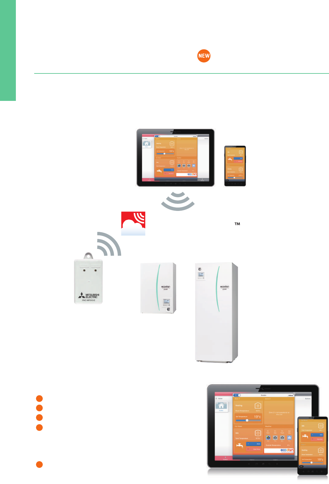
159
MELCloud for fast, easy remote control and monitoring of your ECODAN All A
++
line-up!!
MELCloud is a new Cloud-based solution for controlling ECODAN either locally or remotely by computer, tablet or smartphone via the Internet.
Setting up and remotely operating your ECODAN heating system via MELCloud is simple and straight forward. All you need is wireless
computer connectivity in your home or the building where the ECODAN is installed and an Internet connection on your mobile or fixed terminal.
To set up the system, the router and the ECODAN WiFi interface must be paired, and this is done simply and quickly using the WPS button found
on all mainstream routers.
You can control and check ECODAN via MELCloud from virtually anywhere an Internet connection is available.
That means, thanks to MELCloud, you can use ECODAN much more easily and conveniently.
MELCloud (WiFi interface) for ECODAN
✽
MELCloud uses the PAC-WF010-E interface
MELCloud
✽
Key control and monitoring features
Turn system on/off
See status of each of your heating zones & adjust set points
See the status of your hot water cylinder & boost remotely
Live weather feed from ECODAN location
Holiday mode - Set system parameters while away
Schedule timer - Set 7 day weekly schedule
Frost protection - Set system to run at minimum temperature
Error status
Check energy usage report* *Additional measuring hardware is required.
1
2
3
4
5
*except for ATA & ATW hybrid system, Mr. SLIM
+
Outdoor unit Indoor unit
Seasonal space heating
energy efficiency class
Rated heat output under
average climate conditions
Seasonal space heating
energy efficiency under
average climate conditions
Water heating energy
efficiency under average
climate conditions
Sound power level L
WA
indoor
Sound power level L
WA
outdoor
Seasonal space heating
energy efficiency class
Water heating energy
efficiency class
Rated heat output under
average climate conditions
Seasonal space heating
energy efficiency under
average climate conditions
Water heating energy
efficiency under average
climate conditions
Sound power level L
WA
indoor
Sound power level L
WA
outdoor
kW
4.6
4.6
4.6
4.6
4.3
4.3
4.3
4.3
7.1
7.1
7.1
7.1
10.0
10.0
10.0
10.0
12.0
12.0
12.0
12.0
13.5
13.5
15.5
15.5
9.0
9.0
9.0
9.0
12.7
12.7
12.7
12.7
15.8
15.8
15.8
15.8
23.0
23.0
5.0
5.0
8.5
8.5
10.0
10.0
12.7
12.7
15.8
15.8
7.5
7.5
kW
5.0
5.0
5.0
5.0
4.5
4.5
4.5
4.5
7.2
7.2
7.2
7.2
10.4
10.4
10.4
10.4
12.9
12.9
12.9
12.9
15.3
15.3
17.3
17.3
9.6
9.6
9.6
9.6
13.9
13.9
13.9
13.9
17.0
17.0
17.0
17.0
25.0
25.0
5.0
5.0
8.5
8.5
10.0
10.0
12.7
12.7
15.8
15.8
7.5
7.5
%
170
174
170
174
163
167
163
167
165
167
165
167
164
166
164
166
162
164
162
164
161
163
162
164
171
174
171
174
167
169
167
169
164
165
164
165
164
165
162
162
162
162
164
164
155
155
157
157
163
163
%
109
109
–
–
98
98
–
–
103
103
–
–
103
103
–
–
99
99
–
–
–
–
–
–
103
103
–
–
103
103
–
–
103
103
–
–
–
–
99
–
97
–
100
–
100
–
96
–
98
–
dB
40
40
40
40
40
40
40
40
40
40
40
40
40
40
40
40
40
40
40
40
45
45
45
45
40
40
40
40
40
40
40
40
40
40
40
40
45
45
40
40
40
40
40
40
40
40
40
40
40
40
dB
61
61
61
61
63
63
63
63
68
68
68
68
70
70
70
70
72
72
72
72
78
78
78
78
69
69
69
69
70
70
70
70
70
70
70
70
75
75
61
61
66
66
67
67
67
67
67
67
68
68
%
126
128
126
128
125
128
125
128
127
129
127
129
125
127
125
127
125
127
125
127
125
126
128
129
131
133
131
133
128
130
128
130
127
128
127
128
127
128
127
127
128
128
125
125
126
126
126
126
123
123
%
109
109
–
–
98
98
–
–
103
103
–
–
103
103
–
–
99
99
–
–
–
–
–
–
103
103
–
–
103
103
–
–
103
103
–
–
–
–
99
–
97
–
100
–
100
–
96
–
98
–
dB
40
40
40
40
40
40
40
40
40
40
40
40
40
40
40
40
40
40
40
40
45
45
45
45
40
40
40
40
40
40
40
40
40
40
40
40
45
45
40
40
40
40
40
40
40
40
40
40
40
40
dB
61
61
61
61
63
63
63
63
68
68
68
68
70
70
70
70
72
72
72
72
78
78
78
78
69
69
69
69
70
70
70
70
70
70
70
70
75
75
61
61
66
66
67
67
67
67
67
67
68
68
EHST20D-****
ERST20D-****
EHSD-****
ERSD-****
EHST20D-****
ERST20D-****
EHSD-****
ERSD-****
EHST20C-****
ERST20C-****
EHSC-****
ERSC-****
EHST20C-****
ERST20C-****
EHSC-****
ERSC-****
EHST20C-****
ERST20C-****
EHSC-****
ERSC-****
EHSE-****
ERSE-****
EHSE-****
ERSE-****
EHST20C-****
ERST20C-****
EHSC-****
ERSC-****
EHST20C-****
ERST20C-****
EHSC-****
ERSC-****
EHST20C-****
ERST20C-****
EHSC-****
ERSC-****
EHSE-****
ERSE-****
EHPT20X-****
EHPX-****
EHPT20X-****
EHPX-****
EHPT20X-****
EHPX-****
EHPT20X-****
EHPX-****
EHPT20X-****
EHPX-****
EHST20C-****
EHSC-****
A
++
A
++
A
++
A
++
A
++
A
++
A
++
A
++
A
++
A
++
A
++
A
++
A
++
A
++
A
++
A
++
A
++
A
++
A
++
A
++
A
++
A
++
A
++
A
++
A
++
A
++
A
++
A
++
A
++
A
++
A
++
A
++
A
++
A
++
A
++
A
++
A
++
A
++
A
++
A
++
A
++
A
++
A
++
A
++
A
++
A
++
A
++
A
++
A
+
A
+
Water heating energy
efficiency class
A
A
–
–
A
A
–
–
A
A
–
–
A
A
–
–
A
A
–
–
–
–
–
–
A
A
–
–
A
A
–
–
A
A
–
–
–
–
A
–
A
–
A
–
A
–
A
–
A
–
A
++
A
++
A
++
A
++
A
++
A
++
A
++
A
++
A
++
A
++
A
++
A
++
A
++
A
++
A
++
A
++
A
++
A
++
A
++
A
++
A
++
A
++
A
++
A
++
A
++
A
++
A
++
A
++
A
++
A
++
A
++
A
++
A
++
A
++
A
++
A
++
A
++
A
++
A
++
A
++
A
++
A
++
A
++
A
++
A
++
A
++
A
++
A
++
A
++
A
++
A
A
–
–
A
A
–
–
A
A
–
–
A
A
–
–
A
A
–
–
–
–
–
–
A
A
–
–
A
A
–
–
A
A
–
–
–
–
A
–
A
–
A
–
A
–
A
–
A
–
SUHZ-SW45VA
PUHZ-SW50VKA (-BS)
PUHZ-SW75VHA (-BS)
PUHZ-SW100VHA/YHA (-BS)
PUHZ-SW120VHA/YHA (-BS)
PUHZ-SW160YKA (-BS)
PUHZ-SW200YKA (-BS)
PUHZ-SHW80VHA (-BS)
PUHZ-SHW112VHA/YHA (-BS)
PUHZ-SHW140YHA (-BS)
PUHZ-SHW230YKA2
PUHZ-W50VHA2 (-BS)
PUHZ-W85VHA2 (-BS)
PUHZ-W112VHA (-BS)
PUHZ-HW112YHA2 (-BS)
PUHZ-HW140VHA2/YHA2 (-BS)
PUHZ-FRP71VHA
ATA & ATW hybrid system, Mr. SLIM+
For medium-temperature application For low-temperature application
✽ Based on COMMISSION DELEGATED REGULATION (EU) No 811/2013, average climate conditions
160
MELCloud for fast, easy remote control and monitoring of your ECODAN All A
++
line-up!!
MELCloud is a new Cloud-based solution for controlling ECODAN either locally or remotely by computer, tablet or smartphone via the Internet.
Setting up and remotely operating your ECODAN heating system via MELCloud is simple and straight forward. All you need is wireless
computer connectivity in your home or the building where the ECODAN is installed and an Internet connection on your mobile or fixed terminal.
To set up the system, the router and the ECODAN WiFi interface must be paired, and this is done simply and quickly using the WPS button found
on all mainstream routers.
You can control and check ECODAN via MELCloud from virtually anywhere an Internet connection is available.
That means, thanks to MELCloud, you can use ECODAN much more easily and conveniently.
MELCloud (WiFi interface) for ECODAN
✽
MELCloud uses the PAC-WF010-E interface
MELCloud
✽
Key control and monitoring features
Turn system on/off
See status of each of your heating zones & adjust set points
See the status of your hot water cylinder & boost remotely
Live weather feed from ECODAN location
Holiday mode - Set system parameters while away
Schedule timer - Set 7 day weekly schedule
Frost protection - Set system to run at minimum temperature
Error status
Check energy usage report* *Additional measuring hardware is required.
1
2
3
4
5
*except for ATA & ATW hybrid system, Mr. SLIM
+
Outdoor unit Indoor unit
Seasonal space heating
energy efficiency class
Rated heat output under
average climate conditions
Seasonal space heating
energy efficiency under
average climate conditions
Water heating energy
efficiency under average
climate conditions
Sound power level L
WA
indoor
Sound power level L
WA
outdoor
Seasonal space heating
energy efficiency class
Water heating energy
efficiency class
Rated heat output under
average climate conditions
Seasonal space heating
energy efficiency under
average climate conditions
Water heating energy
efficiency under average
climate conditions
Sound power level L
WA
indoor
Sound power level L
WA
outdoor
kW
4.6
4.6
4.6
4.6
4.3
4.3
4.3
4.3
7.1
7.1
7.1
7.1
10.0
10.0
10.0
10.0
12.0
12.0
12.0
12.0
13.5
13.5
15.5
15.5
9.0
9.0
9.0
9.0
12.7
12.7
12.7
12.7
15.8
15.8
15.8
15.8
23.0
23.0
5.0
5.0
8.5
8.5
10.0
10.0
12.7
12.7
15.8
15.8
7.5
7.5
kW
5.0
5.0
5.0
5.0
4.5
4.5
4.5
4.5
7.2
7.2
7.2
7.2
10.4
10.4
10.4
10.4
12.9
12.9
12.9
12.9
15.3
15.3
17.3
17.3
9.6
9.6
9.6
9.6
13.9
13.9
13.9
13.9
17.0
17.0
17.0
17.0
25.0
25.0
5.0
5.0
8.5
8.5
10.0
10.0
12.7
12.7
15.8
15.8
7.5
7.5
%
170
174
170
174
163
167
163
167
165
167
165
167
164
166
164
166
162
164
162
164
161
163
162
164
171
174
171
174
167
169
167
169
164
165
164
165
164
165
162
162
162
162
164
164
155
155
157
157
163
163
%
109
109
–
–
98
98
–
–
103
103
–
–
103
103
–
–
99
99
–
–
–
–
–
–
103
103
–
–
103
103
–
–
103
103
–
–
–
–
99
–
97
–
100
–
100
–
96
–
98
–
dB
40
40
40
40
40
40
40
40
40
40
40
40
40
40
40
40
40
40
40
40
45
45
45
45
40
40
40
40
40
40
40
40
40
40
40
40
45
45
40
40
40
40
40
40
40
40
40
40
40
40
dB
61
61
61
61
63
63
63
63
68
68
68
68
70
70
70
70
72
72
72
72
78
78
78
78
69
69
69
69
70
70
70
70
70
70
70
70
75
75
61
61
66
66
67
67
67
67
67
67
68
68
%
126
128
126
128
125
128
125
128
127
129
127
129
125
127
125
127
125
127
125
127
125
126
128
129
131
133
131
133
128
130
128
130
127
128
127
128
127
128
127
127
128
128
125
125
126
126
126
126
123
123
%
109
109
–
–
98
98
–
–
103
103
–
–
103
103
–
–
99
99
–
–
–
–
–
–
103
103
–
–
103
103
–
–
103
103
–
–
–
–
99
–
97
–
100
–
100
–
96
–
98
–
dB
40
40
40
40
40
40
40
40
40
40
40
40
40
40
40
40
40
40
40
40
45
45
45
45
40
40
40
40
40
40
40
40
40
40
40
40
45
45
40
40
40
40
40
40
40
40
40
40
40
40
dB
61
61
61
61
63
63
63
63
68
68
68
68
70
70
70
70
72
72
72
72
78
78
78
78
69
69
69
69
70
70
70
70
70
70
70
70
75
75
61
61
66
66
67
67
67
67
67
67
68
68
EHST20D-****
ERST20D-****
EHSD-****
ERSD-****
EHST20D-****
ERST20D-****
EHSD-****
ERSD-****
EHST20C-****
ERST20C-****
EHSC-****
ERSC-****
EHST20C-****
ERST20C-****
EHSC-****
ERSC-****
EHST20C-****
ERST20C-****
EHSC-****
ERSC-****
EHSE-****
ERSE-****
EHSE-****
ERSE-****
EHST20C-****
ERST20C-****
EHSC-****
ERSC-****
EHST20C-****
ERST20C-****
EHSC-****
ERSC-****
EHST20C-****
ERST20C-****
EHSC-****
ERSC-****
EHSE-****
ERSE-****
EHPT20X-****
EHPX-****
EHPT20X-****
EHPX-****
EHPT20X-****
EHPX-****
EHPT20X-****
EHPX-****
EHPT20X-****
EHPX-****
EHST20C-****
EHSC-****
A
++
A
++
A
++
A
++
A
++
A
++
A
++
A
++
A
++
A
++
A
++
A
++
A
++
A
++
A
++
A
++
A
++
A
++
A
++
A
++
A
++
A
++
A
++
A
++
A
++
A
++
A
++
A
++
A
++
A
++
A
++
A
++
A
++
A
++
A
++
A
++
A
++
A
++
A
++
A
++
A
++
A
++
A
++
A
++
A
++
A
++
A
++
A
++
A
+
A
+
Water heating energy
efficiency class
A
A
–
–
A
A
–
–
A
A
–
–
A
A
–
–
A
A
–
–
–
–
–
–
A
A
–
–
A
A
–
–
A
A
–
–
–
–
A
–
A
–
A
–
A
–
A
–
A
–
A
++
A
++
A
++
A
++
A
++
A
++
A
++
A
++
A
++
A
++
A
++
A
++
A
++
A
++
A
++
A
++
A
++
A
++
A
++
A
++
A
++
A
++
A
++
A
++
A
++
A
++
A
++
A
++
A
++
A
++
A
++
A
++
A
++
A
++
A
++
A
++
A
++
A
++
A
++
A
++
A
++
A
++
A
++
A
++
A
++
A
++
A
++
A
++
A
++
A
++
A
A
–
–
A
A
–
–
A
A
–
–
A
A
–
–
A
A
–
–
–
–
–
–
A
A
–
–
A
A
–
–
A
A
–
–
–
–
A
–
A
–
A
–
A
–
A
–
A
–
SUHZ-SW45VA
PUHZ-SW50VKA (-BS)
PUHZ-SW75VHA (-BS)
PUHZ-SW100VHA/YHA (-BS)
PUHZ-SW120VHA/YHA (-BS)
PUHZ-SW160YKA (-BS)
PUHZ-SW200YKA (-BS)
PUHZ-SHW80VHA (-BS)
PUHZ-SHW112VHA/YHA (-BS)
PUHZ-SHW140YHA (-BS)
PUHZ-SHW230YKA2
PUHZ-W50VHA2 (-BS)
PUHZ-W85VHA2 (-BS)
PUHZ-W112VHA (-BS)
PUHZ-HW112YHA2 (-BS)
PUHZ-HW140VHA2/YHA2 (-BS)
PUHZ-FRP71VHA
ATA & ATW hybrid system, Mr. SLIM+
For medium-temperature application For low-temperature application
✽ Based on COMMISSION DELEGATED REGULATION (EU) No 811/2013, average climate conditions

161
SYSTEM
SELECTION
A line-up of three product groups that addresses a wide range of needs.
LGH SERIES
Ceiling-concealed
(150–2500m
3
/h)
VL SERIES
Ceiling-concealed
260m
3
/h
VL SERIES
Wall-mounted
100m
3
/h
SELECT LOSSNAY
SELECT OPTIONS
Select the most appropriate model according to factors such as the shape of the building and ventilation requirements.
• Applications: Oces, Stores, Etc.
• High total heat-exchange eciency
• Excellent airow control
(Extra High, High, Low and Extra Low)
• Multi-ventilation Mode
• Can be interconnected with other Mitsubishi Electric
air conditioners
• Exclusive Lossnay remote-control system
• Mr. Slim remote controller can be used for some systems
• Application: Houses, residences
• Positive/negative pressurization
• Sensible heat recovery suitable for air extraction from
bathrooms and kitchens
• Application: Prefabricated oces (container houses),
Residences, Etc.
• High/Low airow control
• Pull-string switch
LGH-15 to 100RVX-E
LGH-150 and 200RVX-E
Remote controller (PZ-61DR-E)
Model Applicable model
PZ-15RFM-E
PZ-25RFM-E
PZ-35RFM-E
PZ-50RFM-E
PZ-65RFM-E
PZ-80RFM-E
PZ-100RFM-E
1
2
2
2
2
2
2
LGH-15RVX-E
LGH-25RVX-E
LGH-35RVX-E
LGH-50RVX-E
LGH-65RVX-E
LGH-80RVX-E, LGH-150RVX-E (2 sets)
LGH-100RVX-E, LGH-200RVX-E (2 sets)
Filter material
Number
of lters
per set
Non
combustible
ber
(Polyester-
polyolen)
(EU-F7)
Incorporation into the main unit
is
simple, and lter changes can
be
performed via the main unit in-
spection opening.
High-efficiency filter
* Options listed above are exclusively for LGH-_RVX-E models.
120
120
19
Unit:mm
Fan speed selection 4 fan speeds
Ventilation mode selection Energy recovery / Bypass / Auto
Night-purge (time) Any time selectable
Night-purge (fan speed) Selectable from 4 fan speeds
Dip-switch setting and function setting from RC Ye s
Bypass temp. free setting Yes
Heater-On temp. free setting Ye s
Fan power up after installation Yes
0 - 10VDC external input Ye s
ON/OFF timer Yes
Auto-O timer Yes
Weekly timer Ye s
Operation restrictions (ON/OFF, Ventilation mode, fan speed) Ye s
Operation restrictions (Fan speed skip setting) Ye s
Screen contrast adjustment Ye s
Language selection Ye s (8 languages)
Initializing remote controller
Filter cleaning sign Yes
Lossnay core cleaning sign Ye s
Error indication Ye s
Error history Ye s
OA/RA/SA temp. display Ye s
Ye s
LGH-150 to250RVXT-E
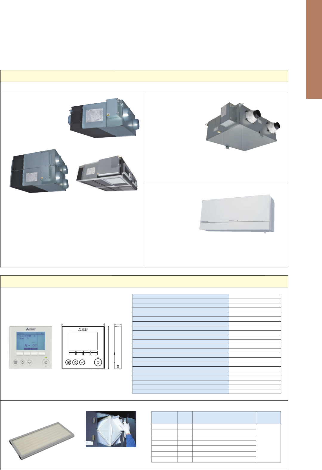
162
SYSTEM
SELECTION
A line-up of three product groups that addresses a wide range of needs.
LGH SERIES
Ceiling-concealed
(150–2500m
3
/h)
VL SERIES
Ceiling-concealed
260m
3
/h
VL SERIES
Wall-mounted
100m
3
/h
SELECT LOSSNAY
SELECT OPTIONS
Select the most appropriate model according to factors such as the shape of the building and ventilation requirements.
• Applications: Oces, Stores, Etc.
• High total heat-exchange eciency
• Excellent airow control
(Extra High, High, Low and Extra Low)
• Multi-ventilation Mode
• Can be interconnected with other Mitsubishi Electric
air conditioners
• Exclusive Lossnay remote-control system
• Mr. Slim remote controller can be used for some systems
• Application: Houses, residences
• Positive/negative pressurization
• Sensible heat recovery suitable for air extraction from
bathrooms and kitchens
• Application: Prefabricated oces (container houses),
Residences, Etc.
• High/Low airow control
• Pull-string switch
LGH-15 to 100RVX-E
LGH-150 and 200RVX-E
Remote controller (PZ-61DR-E)
Model Applicable model
PZ-15RFM-E
PZ-25RFM-E
PZ-35RFM-E
PZ-50RFM-E
PZ-65RFM-E
PZ-80RFM-E
PZ-100RFM-E
1
2
2
2
2
2
2
LGH-15RVX-E
LGH-25RVX-E
LGH-35RVX-E
LGH-50RVX-E
LGH-65RVX-E
LGH-80RVX-E, LGH-150RVX-E (2 sets)
LGH-100RVX-E, LGH-200RVX-E (2 sets)
Filter material
Number
of lters
per set
Non
combustible
ber
(Polyester-
polyolen)
(EU-F7)
Incorporation into the main unit
is
simple, and lter changes can
be
performed via the main unit in-
spection opening.
High-efficiency filter
* Options listed above are exclusively for LGH-_RVX-E models.
120
120
19
Unit:mm
Fan speed selection 4 fan speeds
Ventilation mode selection Energy recovery / Bypass / Auto
Night-purge (time) Any time selectable
Night-purge (fan speed) Selectable from 4 fan speeds
Dip-switch setting and function setting from RC Ye s
Bypass temp. free setting Yes
Heater-On temp. free setting Ye s
Fan power up after installation Yes
0 - 10VDC external input Ye s
ON/OFF timer Yes
Auto-O timer Yes
Weekly timer Ye s
Operation restrictions (ON/OFF, Ventilation mode, fan speed) Ye s
Operation restrictions (Fan speed skip setting) Ye s
Screen contrast adjustment Ye s
Language selection Ye s (8 languages)
Initializing remote controller
Filter cleaning sign Yes
Lossnay core cleaning sign Ye s
Error indication Ye s
Error history Ye s
OA/RA/SA temp. display Ye s
Ye s
LGH-150 to250RVXT-E
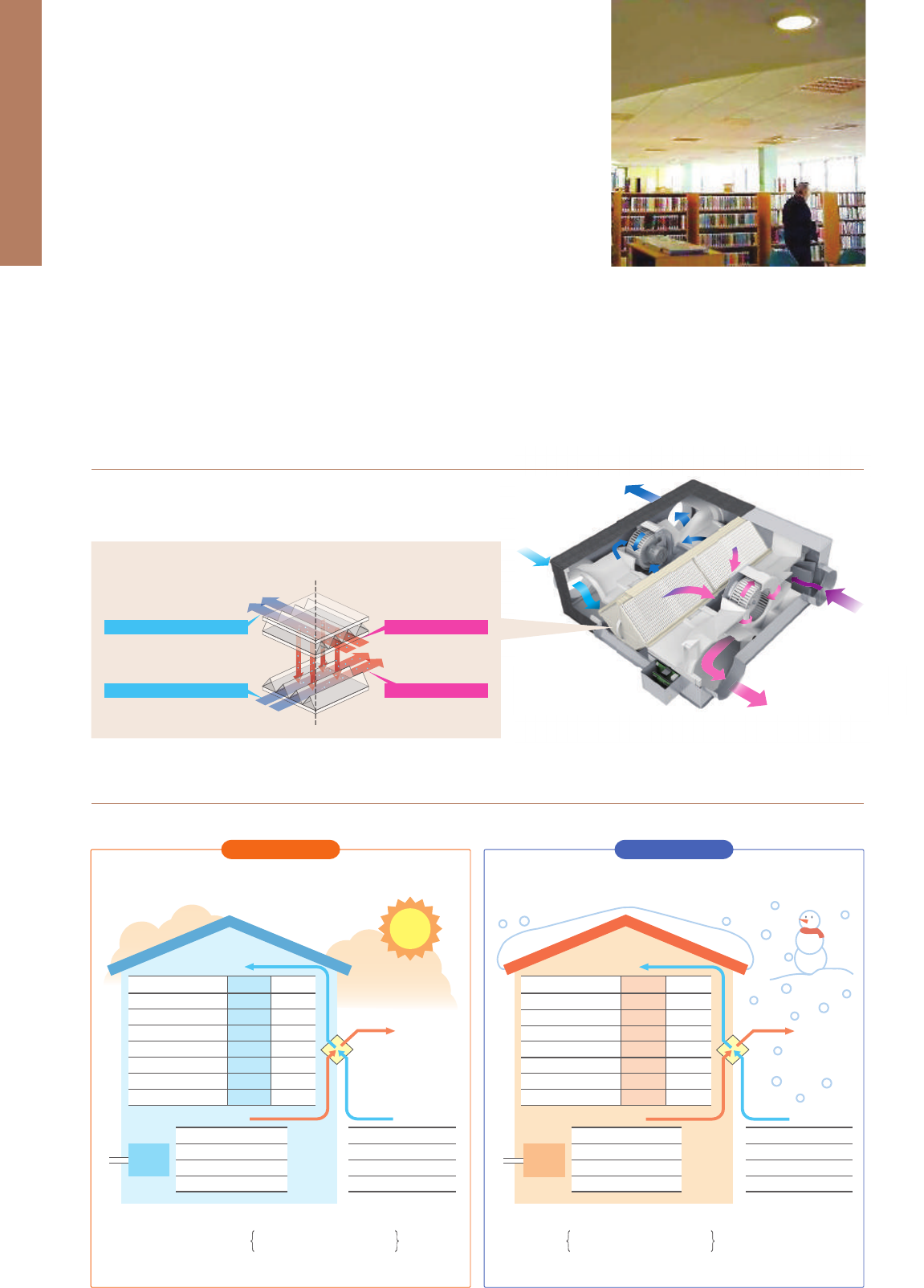
163
LOSSNAY
SYSTEM
Lossnay ventilation systems are renowned industry-wide for their efficiency. They
offer environment-friendly energy recovery and humidity control, and enable air
conditioning systems to simultaneously provide optimum room comfort and
energy savings.
Supply air
Room air
Air
conditioner
Air
conditioner
Dry bulb temperature (ºC)
Absolute humidity (g/kg'(DA))
Relative humidity (%)
Enthalpy (kJ/kg(DA))
Total energy recovery (kW)
Outdoor air load (kW)
Outdoor air load ratio (%)
LOSSNAY
28
13.3
56
62.1
7.5
3.1
29
33
20.1
63
84.6
0
10.6
100
Conventional
ventilator
Dry bulb temperature
Absolute humidity
Relative humidity
Enthalpy
Dry bulb temperature
Absolute humidity
Relative humidity
Enthalpy
Outdoor air
Exhaust air
Supply air
Room air
Dry bulb temperature (ºC)
Absolute humidity (g/kg'(DA))
Relative humidity (%)
Enthalpy (kJ/kg(DA))
Total energy recovery (kW)
Outdoor air load (kW)
Outdoor air load ratio (%)
LOSSNAY
16
5.2
46
29.2
8.2
3.1
28
Conventional
ventilator
0
1.9
50
4.7
0
11.3
100
Dry bulb temperature
Absolute humidity
Relative humidity
Enthalpy
Outdoor air
Exhaust air
Dry bulb temperature
Absolute humidity
Relative humidity
Enthalpy
0ºC
1.9g/kg'(DA)
50%
4.7kJ/kg(DA)
20ºC
7.3g/kg'(DA)
50%
38.5kJ/kg(DA)
33ºC
20.1g/kg'(DA)
63%
84.6kJ/kg(DA)
26ºC
10.5g/kg'(DA)
50%
52.9kJ/kg(DA)
Heat recovery calculation
Indoor supply-air
temperature
(
º
C
)
Indoor
temperature
(
º
C
)
Outdoor
temperature
(
º
C
)
_
×
Temp recovery
efficiency (%)
Outdoor
temperature
(
º
C
)
+
Calculation example: 16ºC = (20ºC
_
0ºC) × 80% + 0ºC
=
Heat recovery calculation
Indoor supply-air
temperature
(
º
C
)
Outdoor
temperature
(
º
C
)
Indoor
temperature
(
º
C
)
Outdoor
temperature
(
º
C
)
_
_
×
Temp recovery
efficiency (%)
Calculation example: 28ºC = 33ºC
_
(33ºC
_
26ºC) × 72%
=
*The above applies to the case of LGH-100RVX (fan speed 4).
● Ventilation with maximised comfort
Air similar to the conditions of the heated (humidified)
indoor air is supplied.
In summer In winter
Air similar to the conditions of the cooled (dehumidified)
indoor air is supplied.
InsideOutside
Outside exhaust air outlet (EA)
Outside air intake (OA)
Inside return air (RA)
Inside supply air (SA)
● The concept of sensible heat and latent heat exchange
using Lossnay core
With operation from PZ-61DR-E, it is possible to select manual switching or automatic switching between “Lossnay ventilation (with heat exchange)”
and “Bypass ventilation (without heat exchange)”.
Indoor Air Quality Inside a Building is Optimised Through Temperature
and Humidity Exchange by Lossnay
Lossnay is a total heat exchange ventilation system that uses paper
characteristics to perform temperature (sensible heat) and humidity
(latent heat) exchange.
What can be Improved by Introducing Lossnay?
Auto Ventilation Mode has Improved [PZ-61DR-E]
By providing a range of air volume for each fan speed, sound levels can be reduced to achieve low noise.
Low Noise Design
External static pressure has been improved
compared to previous models.
By increasing the external static pressure,
highly flexible duct work becomes possible
thus renewal from existing equipment is easy.
Improved External Static Pressure
0
200
400
600
800
1000
1200
Input power (W)
15 type25 type35 type50 type
Model
65 type80 type100 type150 type 200 type
Previous model
10
8
20
18
16
14
12
30
28
26
24
22
40
38
36
34
32
Indoor temperature (°C)
Setting item BSetting item B
Lossnay ventilation areaLossnay ventilation area
Bypass
ventilation area
Outdoor temperature (°C)
810121416182022242628303234363840
Lossnay core
Damper
Stale
exhaust air
Fresh air
from outside
Stale room
air extracted
Fresh air supply
to the room
Lossnay core
Damper
Stale
exhaust air
Fresh air
from outside
Stale room
air extracted
Fresh air supply
to the room
With the previous model, the auto ventilation mode is based on the initial setting
condition; however, with the new model it becomes possible to set three setting
points, as shown in the table on the right.
*Settings can only be made using the PZ-61DR-E
What is Lossnay ventilation?
Room air is discharged to outside
via Lossnay core. Heat exchanged
outside air is supplied to the room.
In summer and winter, air condition-
ing energy can be recovered by
Lossnay unit.
What is bypass ventilation?
Stare room air is discharged to out-
side without passing through the
Lossnay core.
In spring and fall when air condition-
ing is not necessary, the unit oper-
ates in bypass ventilation mode.
● By-pass/Lossnay ventilation map in automatic ventilation mode
● Noise comparison between new and previous models (new model: fan speed 3, previous model: High)
A high efficiency DC motor has been adopted. Compared to models with an AC motor, power consumption is reduced.
Power Consumption Reduced Further with Introduction of DC Motor
● Comparison between new and previous power consumption (New model: Fan Speed 4, Previous model: Extra-High)
Noise (dB)
15 type25 type35 type50 type
Model
65 type80 type100 type150 type200 type
20
30
40
10
Setting item CSetting item C
When the equipment layout is reviewed
during renewal, even if new obstacles
are found, installation can be smooth.
Often complicated
installation under the roof
can be handled flexibly!
New model
Previous model New model
Setting item ASetting item A
When Lossnay is
connected with Mr.Slim or C/M,
setting temp will be the min
limit of bypass ventilation.
When Lossnay is
connected with Mr.Slim or C/M,
setting temp will be the min
limit of bypass ventilation.
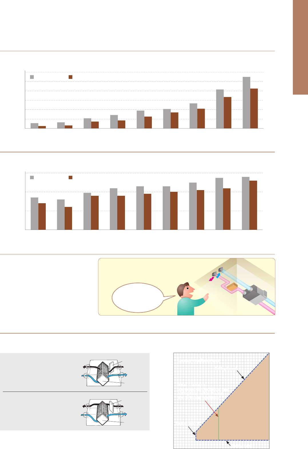
164
LOSSNAY
SYSTEM
Lossnay ventilation systems are renowned industry-wide for their efficiency. They
offer environment-friendly energy recovery and humidity control, and enable air
conditioning systems to simultaneously provide optimum room comfort and
energy savings.
Supply air
Room air
Air
conditioner
Air
conditioner
Dry bulb temperature (ºC)
Absolute humidity (g/kg'(DA))
Relative humidity (%)
Enthalpy (kJ/kg(DA))
Total energy recovery (kW)
Outdoor air load (kW)
Outdoor air load ratio (%)
LOSSNAY
28
13.3
56
62.1
7.5
3.1
29
33
20.1
63
84.6
0
10.6
100
Conventional
ventilator
Dry bulb temperature
Absolute humidity
Relative humidity
Enthalpy
Dry bulb temperature
Absolute humidity
Relative humidity
Enthalpy
Outdoor air
Exhaust air
Supply air
Room air
Dry bulb temperature (ºC)
Absolute humidity (g/kg'(DA))
Relative humidity (%)
Enthalpy (kJ/kg(DA))
Total energy recovery (kW)
Outdoor air load (kW)
Outdoor air load ratio (%)
LOSSNAY
16
5.2
46
29.2
8.2
3.1
28
Conventional
ventilator
0
1.9
50
4.7
0
11.3
100
Dry bulb temperature
Absolute humidity
Relative humidity
Enthalpy
Outdoor air
Exhaust air
Dry bulb temperature
Absolute humidity
Relative humidity
Enthalpy
0ºC
1.9g/kg'(DA)
50%
4.7kJ/kg(DA)
20ºC
7.3g/kg'(DA)
50%
38.5kJ/kg(DA)
33ºC
20.1g/kg'(DA)
63%
84.6kJ/kg(DA)
26ºC
10.5g/kg'(DA)
50%
52.9kJ/kg(DA)
Heat recovery calculation
Indoor supply-air
temperature
(
º
C
)
Indoor
temperature
(
º
C
)
Outdoor
temperature
(
º
C
)
_
×
Temp recovery
efficiency (%)
Outdoor
temperature
(
º
C
)
+
Calculation example: 16ºC = (20ºC
_
0ºC) × 80% + 0ºC
=
Heat recovery calculation
Indoor supply-air
temperature
(
º
C
)
Outdoor
temperature
(
º
C
)
Indoor
temperature
(
º
C
)
Outdoor
temperature
(
º
C
)
_
_
×
Temp recovery
efficiency (%)
Calculation example: 28ºC = 33ºC
_
(33ºC
_
26ºC) × 72%
=
*The above applies to the case of LGH-100RVX (fan speed 4).
● Ventilation with maximised comfort
Air similar to the conditions of the heated (humidified)
indoor air is supplied.
In summer In winter
Air similar to the conditions of the cooled (dehumidified)
indoor air is supplied.
InsideOutside
Outside exhaust air outlet (EA)
Outside air intake (OA)
Inside return air (RA)
Inside supply air (SA)
● The concept of sensible heat and latent heat exchange
using Lossnay core
With operation from PZ-61DR-E, it is possible to select manual switching or automatic switching between “Lossnay ventilation (with heat exchange)”
and “Bypass ventilation (without heat exchange)”.
Indoor Air Quality Inside a Building is Optimised Through Temperature
and Humidity Exchange by Lossnay
Lossnay is a total heat exchange ventilation system that uses paper
characteristics to perform temperature (sensible heat) and humidity
(latent heat) exchange.
What can be Improved by Introducing Lossnay?
Auto Ventilation Mode has Improved [PZ-61DR-E]
By providing a range of air volume for each fan speed, sound levels can be reduced to achieve low noise.
Low Noise Design
External static pressure has been improved
compared to previous models.
By increasing the external static pressure,
highly flexible duct work becomes possible
thus renewal from existing equipment is easy.
Improved External Static Pressure
0
200
400
600
800
1000
1200
Input power (W)
15 type25 type35 type50 type
Model
65 type80 type100 type150 type 200 type
Previous model
10
8
20
18
16
14
12
30
28
26
24
22
40
38
36
34
32
Indoor temperature (°C)
Setting item BSetting item B
Lossnay ventilation areaLossnay ventilation area
Bypass
ventilation area
Outdoor temperature (°C)
810121416182022242628303234363840
Lossnay core
Damper
Stale
exhaust air
Fresh air
from outside
Stale room
air extracted
Fresh air supply
to the room
Lossnay core
Damper
Stale
exhaust air
Fresh air
from outside
Stale room
air extracted
Fresh air supply
to the room
With the previous model, the auto ventilation mode is based on the initial setting
condition; however, with the new model it becomes possible to set three setting
points, as shown in the table on the right.
*Settings can only be made using the PZ-61DR-E
What is Lossnay ventilation?
Room air is discharged to outside
via Lossnay core. Heat exchanged
outside air is supplied to the room.
In summer and winter, air condition-
ing energy can be recovered by
Lossnay unit.
What is bypass ventilation?
Stare room air is discharged to out-
side without passing through the
Lossnay core.
In spring and fall when air condition-
ing is not necessary, the unit oper-
ates in bypass ventilation mode.
● By-pass/Lossnay ventilation map in automatic ventilation mode
● Noise comparison between new and previous models (new model: fan speed 3, previous model: High)
A high efficiency DC motor has been adopted. Compared to models with an AC motor, power consumption is reduced.
Power Consumption Reduced Further with Introduction of DC Motor
● Comparison between new and previous power consumption (New model: Fan Speed 4, Previous model: Extra-High)
Noise (dB)
15 type25 type35 type50 type
Model
65 type80 type100 type150 type200 type
20
30
40
10
Setting item CSetting item C
When the equipment layout is reviewed
during renewal, even if new obstacles
are found, installation can be smooth.
Often complicated
installation under the roof
can be handled flexibly!
New model
Previous model New model
Setting item ASetting item A
When Lossnay is
connected with Mr.Slim or C/M,
setting temp will be the min
limit of bypass ventilation.
When Lossnay is
connected with Mr.Slim or C/M,
setting temp will be the min
limit of bypass ventilation.
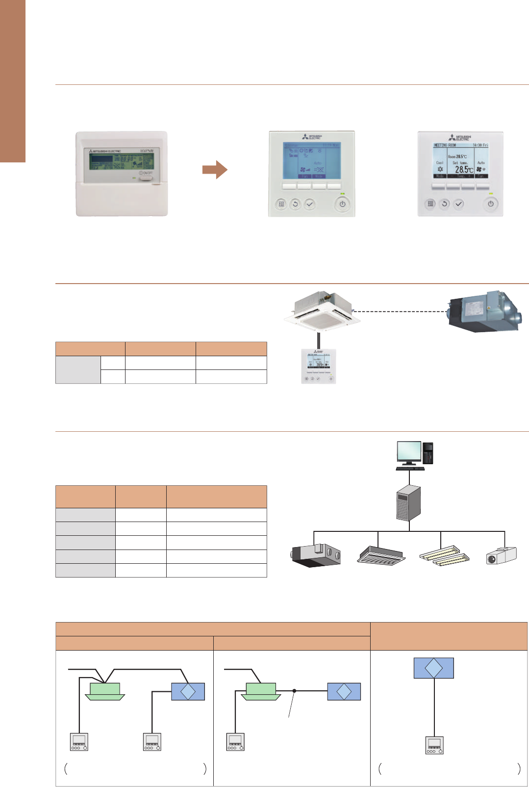
165
The unified design of the PAR-32MAA air conditioner remote controller improves installation appearance.
Full-dot backlit LCD makes it easy to see and control the unit.
Unified Remote-control Design Centralised Controller System
In an easy and flexible manner, an optimum system can be established according to the scale of facilities.
- Implements control on up to 50 indoor units of air-conditioning equipment.
- By using three units of expansion controller “AE-50E”, the centralized control is implemented for the maximum of 200 indoor units.
- Connection with PC allows implementation of control on more than 200 indoor units via Web browser.*
*Please contact your local distributor for when the feature is supported.
Features of New Centralised Controller “AE-200E”
For the specified high and low air volume of the air conditioner,
two types of air volumes can be selected, respectively, providing
more flexible setting options.
Improved Air Volume Setting Flexibility when Simultaneously Operating
with Air Conditioner
Using a 0-10V signal from the building management system,
the air volume of the Lossnay unit can be changed.
Improved Control with a BMS System
The New Remote Controller PZ-61DR-E Enables Simple Control Setting
PC
BMS
Lossnay Air conditioning Lighting system Surveillance camera
system
Previous remote controller New remote controller Air conditioner remote controller
PZ-60DR-E PZ-61DR-E PAR-32MAA
PAR-32MAA
Mr.Slim
City Multi
Previous model
Low
High or Extra-High
New model
Fan Speed 1 or 2*
Fan Speed 3 or 4*
Low
High
-
1
2
3
4
0 -1.0
1.5 - 2.5
3.5 - 4.5
5.5 - 7.0
8.5 - 10.0
Available
Not available
Not available
Not available
Not available
Fan speed
Input voltage
[
VDC
]
Fan speed changing from
remote controller
*factory setting
City Multi
M-NET transmission line
Mr.Slim Lossnay
RVX
Lossnay
RVX
Option 1: Slim-Lossnay connection cable
(Impossible to use Lossnay remote
controller)
Lossnay remote
controller
PZ-61DR-E
Lossnay remote
controller
PZ-61DR-E can
be connected.
Lossnay RVX
(Max 15 units)
PZ-43SMF-E can be connected however function is
limited.
PZ-43SMF-E can be connected however function is
limited.
Option 2: PAC-SF40RM-E
(Possible to use Lossnay remote
controller)
Interlocked with Air conditioners
Lossnay independent
Interlocked with City Multi Interlocked with Mr.Slim
●
Connection example: BMS (Building Management System)
●
System structure
Centralised controller
AE-200E
Outdoor unit
Network remote
controller
Network remote
controller
Lossnay
RVX
Lossnay remote
controller
PZ-61DR-E
Lossnay remote
controller
PZ-61DR-E
Lossnay remote
controller
PZ-61DR-E
Lossnay
RVX
Lossnay
RVX
Interlocked with
City Multi indoor units
Lossnay units only
Indoor unit Indoor unit
M-NET
adapter
Interlocked with
Mr. Slim indoor units
Mr.Slim
remote controller
Mr.Slim
outdoor unit
Mr.Slim
indoor unit
Lossnay
RVX
Ext. signal source
Interlocked with
external devices
Lossnay
RVX
Lossnay remote
controller
PZ-61DR-E
O
Internet
Switching Hub
Hub
LAN
(100BASE-TX)
A Control
Central Control PC
(TG-2000A)
*Ver. 6.50 or later
Remote
Monitoring PC
Hub
DIDO Controller (PAC-YG66DCA)
General Equipment
Temp/Humidity sensor
Watt hour meter
AI Controller (PAC-YG63MCA)
PI Controller (PAC-YG60MCA)
Note: Use a security device such as a VPN router when connecting
the AG-150A/AE-200E to the Internet to prevent unauthorised access.
AE-200E
M-NET
M-NET
Service company / Sales office
Mobile phone
of service person
Remote
monitoring PC
M-NET
M-NET
adapter
AE-
200
E
Remote monitoring
via a Web browser
Remote monitoring
via a Web browser
VPN
Router
VPN
Router
Modem
Power supply unit
(PAC-SC51KUA)
Lights Ventilation
Modem
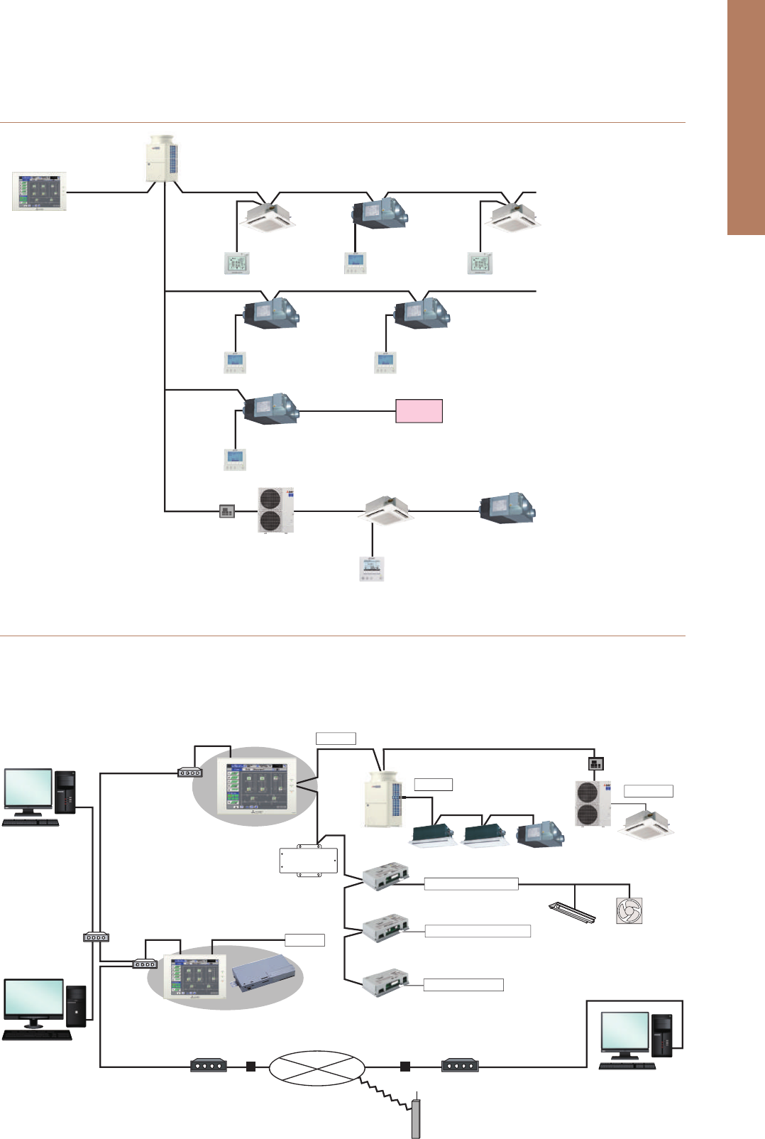
166
The unified design of the PAR-32MAA air conditioner remote controller improves installation appearance.
Full-dot backlit LCD makes it easy to see and control the unit.
Unified Remote-control Design Centralised Controller System
In an easy and flexible manner, an optimum system can be established according to the scale of facilities.
- Implements control on up to 50 indoor units of air-conditioning equipment.
- By using three units of expansion controller “AE-50E”, the centralized control is implemented for the maximum of 200 indoor units.
- Connection with PC allows implementation of control on more than 200 indoor units via Web browser.*
*Please contact your local distributor for when the feature is supported.
Features of New Centralised Controller “AE-200E”
For the specified high and low air volume of the air conditioner,
two types of air volumes can be selected, respectively, providing
more flexible setting options.
Improved Air Volume Setting Flexibility when Simultaneously Operating
with Air Conditioner
Using a 0-10V signal from the building management system,
the air volume of the Lossnay unit can be changed.
Improved Control with a BMS System
The New Remote Controller PZ-61DR-E Enables Simple Control Setting
PC
BMS
Lossnay Air conditioning Lighting system Surveillance camera
system
Previous remote controller New remote controller Air conditioner remote controller
PZ-60DR-E PZ-61DR-E PAR-32MAA
PAR-32MAA
Mr.Slim
City Multi
Previous model
Low
High or Extra-High
New model
Fan Speed 1 or 2*
Fan Speed 3 or 4*
Low
High
-
1
2
3
4
0 -1.0
1.5 - 2.5
3.5 - 4.5
5.5 - 7.0
8.5 - 10.0
Available
Not available
Not available
Not available
Not available
Fan speed
Input voltage
[
VDC
]
Fan speed changing from
remote controller
*factory setting
City Multi
M-NET transmission line
Mr.Slim Lossnay
RVX
Lossnay
RVX
Option 1: Slim-Lossnay connection cable
(Impossible to use Lossnay remote
controller)
Lossnay remote
controller
PZ-61DR-E
Lossnay remote
controller
PZ-61DR-E can
be connected.
Lossnay RVX
(Max 15 units)
PZ-43SMF-E can be connected however function is
limited.
PZ-43SMF-E can be connected however function is
limited.
Option 2: PAC-SF40RM-E
(Possible to use Lossnay remote
controller)
Interlocked with Air conditioners
Lossnay independent
Interlocked with City Multi Interlocked with Mr.Slim
●
Connection example: BMS (Building Management System)
●
System structure
Centralised controller
AE-200E
Outdoor unit
Network remote
controller
Network remote
controller
Lossnay
RVX
Lossnay remote
controller
PZ-61DR-E
Lossnay remote
controller
PZ-61DR-E
Lossnay remote
controller
PZ-61DR-E
Lossnay
RVX
Lossnay
RVX
Interlocked with
City Multi indoor units
Lossnay units only
Indoor unit Indoor unit
M-NET
adapter
Interlocked with
Mr. Slim indoor units
Mr.Slim
remote controller
Mr.Slim
outdoor unit
Mr.Slim
indoor unit
Lossnay
RVX
Ext. signal source
Interlocked with
external devices
Lossnay
RVX
Lossnay remote
controller
PZ-61DR-E
O
Internet
Switching Hub
Hub
LAN
(100BASE-TX)
A Control
Central Control PC
(TG-2000A)
*Ver. 6.50 or later
Remote
Monitoring PC
Hub
DIDO Controller (PAC-YG66DCA)
General Equipment
Temp/Humidity sensor
Watt hour meter
AI Controller (PAC-YG63MCA)
PI Controller (PAC-YG60MCA)
Note: Use a security device such as a VPN router when connecting
the AG-150A/AE-200E to the Internet to prevent unauthorised access.
AE-200E
M-NET
M-NET
Service company / Sales office
Mobile phone
of service person
Remote
monitoring PC
M-NET
M-NET
adapter
AE-
200
E
Remote monitoring
via a Web browser
Remote monitoring
via a Web browser
VPN
Router
VPN
Router
Modem
Power supply unit
(PAC-SC51KUA)
Lights Ventilation
Modem
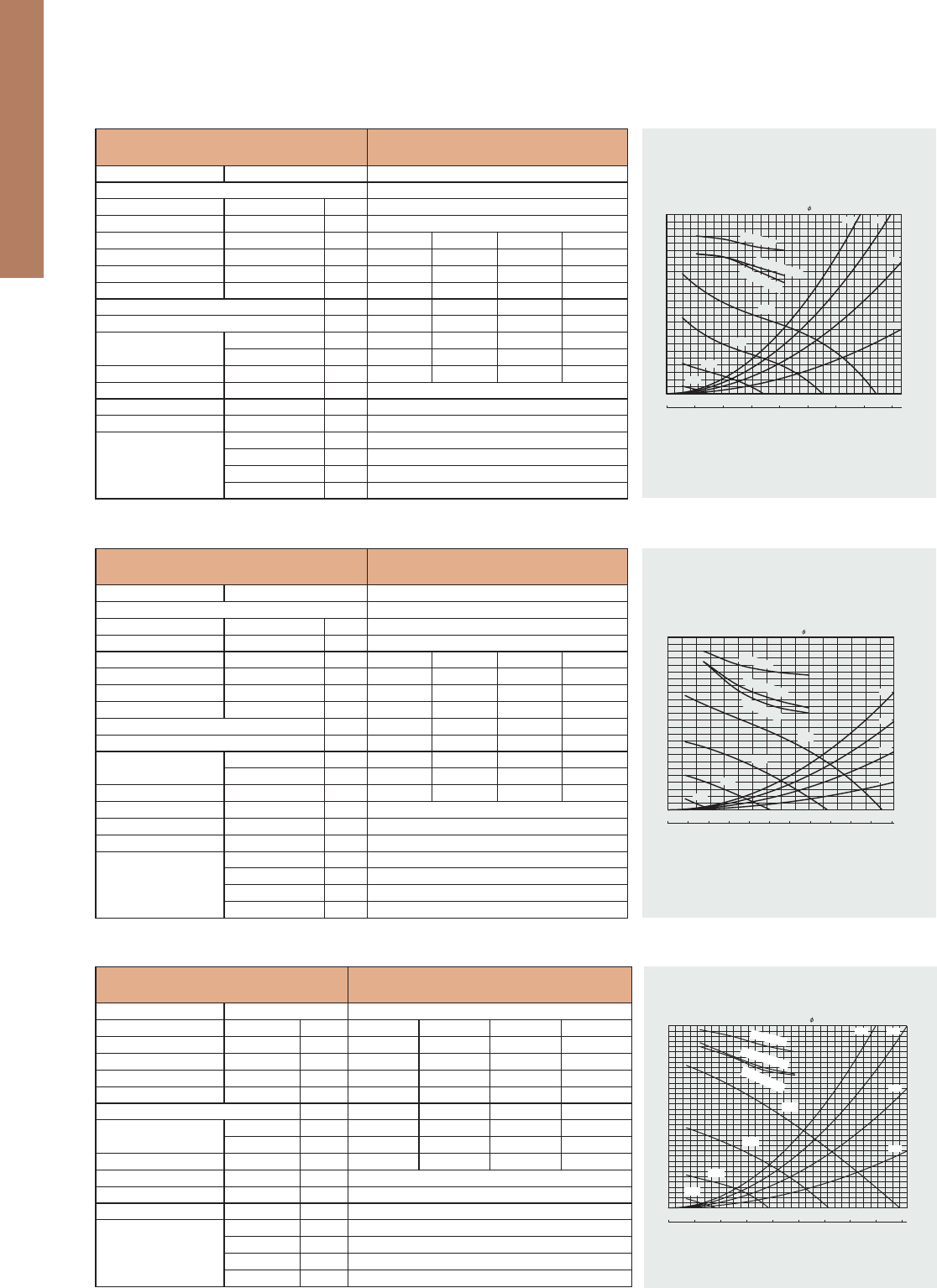
Specications / Dimensions
LGH-200RVX-E
Unit: mm
Model
LGH-200RVX-E
Electrical power supply 220-240V/50Hz, 220V/60Hz
Ventilation mode Heat recovery mode Bypass mode
Fan speed SP4 SP3 SP2 SP1 SP4 SP3 SP2 SP1
Running current (A) 4.88 2.20 0.88 0.33 4.54 2.06 0.87 0.35
Input power (W) 850 400 15342 853 372 15049
Air volume
(m
3
/h) 2000 1500 1000 500 2000 1500 1000 500
(L/s) 556 417 278 139 556 417 278 139
External static pressure (Pa) 150843810150 84 38 10
Temperature exchange eciency (%) 80.0 83.0 86.5 89.5
----
Enthalpy exchange eciency (%)
Heating 72.5 74.0 78.0 87.0
----
Cooling 71.0 73.0 77.0 85.5
----
Noise (dB)
(Measured at 1.5m under the center
of unit in an anechoeic chamber)
40.0 36.0 28.0 18.0 41.0 36.0 27.0 19.0
Weight (kg) 110
*The Air outlets noise (45 angle,1.5meters in front of the unit) is about 21dB greater than the indicated value.(at Fan speed 4)
*The running current, the input power, the eciency and the noise are based on the rating air volume, and 230V/50Hz.
*For the specication at the other frequency contact your dealer.
*Use this unit between static pressure 50Pa and 220Pa at Fan speed4. Otherwise the motor protection may work and reduce its output or the noise level might be larger.
0 100 200 300 400 500 600 700 800
60
70
80
90
0
50
100
150
200
300
350
250
0 500 1000 1500 2000 2500 3000
Exchange efficiency (%)
Static pressure (Pa)
Air volume
(m
3
/h)
SP1
SP2
SP3
SP4
Temper
ature
Ent
h
a
l
p
y
h
e
a
t
i
n
g
En
th
a
l
py co
o
li
n
g
(L/s)
Bypass damper plate Ceiling suspension fixture (4-15 X 30 oval)
OA
(outside air intake)
EA
(exhaust air outlet)
Power supply cable opening
RA
(return air)
SA
(supply air)
Air exhaust fan
High-Efficiency filter (sold separately) attachment position
Lossnay core
Air filters
More than 600
150 to 250
Core,
air filter,
High-Efficiency filter,
fan,
maintenance space
Inspection
opening
450 x 450
or more
Air supply fan
Control box
Maintenance cover
1010
4040
404
808
1144
44
79
917
917
270270
115
26
1272
1231
700
40
258
242
258
242
Supply
voltage
(V)
1-phase
220~240
*The value of noise was measured at an anechoic chamber. it may vary depending on the room structure, building materials or the way the main was installed.
Power supply
frequency
(Hz)
50
Fan speed
Hi
Lo
Power
consumption
(W)
132-146
82-95
(m
3
/h)
Air volume
400
250
(L/s)
111
69
Temperature
recovery
eciency
(%)
60
66
Enthalpy recovery eciency
(%)
45
54
CoolingHeating
40
48
Noise
(dB(A))
41-43
32-34
Weight
(kg)
25
Exchange
efficiency
(%)
50Hz
Low
High
Entha
lpy recovery ef
ficiency (Cooling
)
Enthalpy recovery ef
ficiency (Heating
)
Temperature recovery ef
ficiency
External static pressure
(Pa)
80
70
60
50
40
0 100 200 300 400 500
100
200
300
Air volume (m
3
/h)
LGH-150RVXT-E
116
117
120
20.4
6.5
12.2
Power
lamp
Fan speed
selector switch
Power switch Switch box
Terminal
board
600
900
693
255
495
68
845
127.5
98
290
15
(Outside-
air intake)
Power supply terminal
block
* Power supply cord
opening at the top
*Power supply cord opening
Ceiling suspension
fixture (4 pcs.)
(Exhaust-
air outlet)
RA
(Return air)
Control Switch (PZ-03SLP-E)
Unit: mm
VL-100EU5-E
Fan speed
Supply voltage
(V)
220
230
240
220
Power line frequency
(Hz)
50
50
50
60
Temp. exchange
eciency
(%)
Power consumption
(W)
Noise
(dB)
Air volume
(
m
3
/h
)
Weight
(kg)
73
80
73
80
72
79
73
80
HI
LO
HI
LO
HI
LO
HI
LO
30
13
31
15
34
17
34
17
36.5
24
37
25
38
27
38
25
100
55
105
60
106
61
103
57
7.5
226
12
FRONT PANEL
(OPEN POSITION)
FRONT PANEL LOUVER
(HORIZONTAL POSITION)
FRONT PANEL LOUVER
(VERTICAL POSITION)
FRONT PANEL
(CLOSED POSITION)
EDGE OF MAIN UNIT
420
REQUIRE TO BE SECURED
REQUIRE TO BE SECURED
ABLE)
(ADJUST
(ADJUSTABLE)
AIR INTAKE HOLE
ø85 to ø90 WALL HOLE
40
108
11995
25
15
95.5
PITCH 20X10=200
265
13.5238.5
183min
from nearest
obstruction
233min
75
87
267.5
554
292
75
(ADJUST
ABLE)
MOUNTING HOLES
36×ø6
530
360min from nearest obstruction
200(MIN)
350(MAX)
360min
620
AIR EXHAUST HOLE
ø85 to ø90 WALL HOLE
OU
TE
R
DI
A
OUTER DI
A
ø
7
5×
2
ø
7
9
×2
SHUTTER KNOB
WALL THICKNESS
SHUTTER KNOB
FRESH AIR SUPPLY
90 140
620
54
200
5°
ø150
106
50 to 550
22
17
9725
POWER CORD HOLE
(CLOSED POSITION) (OPEN POSITION)
INDOOR AIR EXHAUST
MOUNTING PLATE
Unit: mm
VL-100U5-E
Fan speed
Supply voltage
(V)
220
230
240
220
Power line frequency
(Hz)
50
50
50
60
Temp. exchange
eciency
(%)
Power consumption
(W)
Noise
(dB)
Air volume
(
m
3
/h
)
Weight
(kg)
73
80
73
80
72
79
73
80
HI
LO
HI
LO
HI
LO
HI
LO
30
13
31
15
34
17
34
17
36.5
24
37
25
38
27
38
25
100
55
105
60
106
61
103
57
7.5
226
12
FRONT PANEL
(OPEN POSITION)
FRONT PANEL LOUVER
(HORIZONTAL POSITION)
FRONT PANEL LOUVER
(VERTICAL POSITION)
FRONT PANEL
(CLOSED POSITION)
EDGE OF MAIN UNIT
420
REQUIRE TO BE SECURED
REQUIRE TO BE SECURED
ABLE)
(ADJUST
(ADJUSTABLE)
AIR INTAKE HOLE
ø85 to ø90 WALL HOLE
40
108
11995
25
15
95.5
PITCH 20X10=200
265
13.5238.5
183min
from nearest
obstruction
233min
MOUNTING PLATE
75
87
267.5
554
292
75
(ADJUST
ABLE)
MOUNTING HOLES
36×ø6
530
360min from nearest obstruction
200(MIN)
350(MAX)
360min
620
AIR EXHAUST HOLE
ø85 to ø90 WALL HOLE
O
UTER
D
I
A
OUTER DIA
ø75×
2
ø7
9
×2
175
SHUTTER KNOB
WALL THICKNESS
SHUTTER KNOB
FRESH AIR SUPPLY
252
90 140
620
54
200
5°
ø150
106
50 to 550
22
17
(OPEN POSITION)
INDOOR AIR EXHAUST
(CLOSED POSITION)
Unit: mm
ø200
Supply
volta
ge
(
V
)
1-
p
has
e
220
~
2
4
0
*The value o
f
noise was measured at an anechoic chamber. it may vary depending on the room structure, building materials or the way the main was installed
.
Power
supply
frequenc
y
(
Hz
)
5
0
Fan s
p
ee
d
Hi
L
o
Power
consum
p
tio
n
(
W
)
13
2-14
6
8
2-
95
(m
3
/h
)
Air
volume
4
00
2
50
(
L/s
)
11
1
69
recover
y
e
cienc
y
(
%
)
60
66
(
%
)
4
5
5
4
Coolin
g
Heat
i
n
g
40
48
N
oi
s
e
(
dB
(
A
))
4
1-4
3
3
2-
34
Wei
g
h
t
(
k
g)
2
5
Exchan
g
e
e
ff
icienc
y
(
%
)
50
Hz
L
o
w
g
High
Entha
lpy recovery ef
ficiency (Cooling
)
E
Enthalpy recovery ef
ficiency (Heating
)
Temperature recovery ef
ficiency
E
xternal static pressure
(
Pa
)
80
70
60
5
0
40
0
1
00
2
00
300
4
00 5
00
100
2
00
300
Air volume
(
m
3
/h
)
1
1
6
11
7
12
0
20 4
20
.
4
6
.5
12 2
12
.
2
P
o
w
e
e
r
lam
p
Fan s
p
eed
selector switch
P
ower switch
S
witch box
T
erminal
boa
r
d
6
00
900
6
9
3
2
5
5
4
9
5
6
8
8
8
4
5
1
2
7
.
5
9
8
2
9
0
15
(
Outside-
air intake
)
Power supply terminal
b
lock
*
Power supply cord
openin
g
at the top
*
Power supply cord openin
g
Ceilin
g
suspension
fixture
(
4
p
cs.
)
(
Exhaust-
air outlet
)
RA
(
Return air
)
C
o
ntr
ol
Switc
h
(
PZ-03SLP-E
)
U
n
i
t
:
mm
ø2
00
167
MODEL
LGH-15RVX-E
Electrical power supply V/Phase/Hz
220-240 / 1 / 50
Energy Efficiency Class (S.E.C.)
A (-40,0)
ErP
1
Data Flow rate max m
3
/h
137
Sound power level max
dB(A)
41
Fan Speed
SP4 SP3 SP2 SP1
Running current A
0,40-0,41 0,24-0,25 0,15 0,10
Power input W
49-52 28 14 7-8
Air Volume m
3
/h
150 113 75 38
External static pressure Pa
95 53,5 24 6
Exchange temperature efficiency %
80,0 81,0 83,0 84,0
Exchange enthalpy
efficiency
Cooling %
71,0 74,5 78,0 79
Heating %
73,0 75,5 78,0 79,0
Sound pressure level dB(A)
28-29 24 19 17-18
Ducts: Nr, diameter mm
4 x 100
Weight kg
20
Dimensions HxWxD mm
289x610x780
"Guaranteed Opera-
ting Range
(Continuous operation)*”
T. ext °C
-10 ~ +40
UR ext max %
80
T. int max °C
40
UR int max %
80
Specifications
1
According to 1254/2014 regulation
020406080 100 120 140 160 180
60
70
80
90
0
50
100
150
300
200
350
250
0 100 200 600400 500300
Exchange efficiency (%)
Static pressure (Pa)
Air volume
(m
3
/h)
SP1
SP2
SP3
SP4
150mm dia straight pipe length
T
empe
rature
Enth
a
lp
y
heatin
g
Enth
a
lp
y
co
o
lin
g
(L/s)
20m
10m
40m 30m
MODEL
LGH-35RVX-E
Electrical power supply V/Phase/Hz
220-240 / 1 /50
Fan Speed
SP4 SP3 SP2 SP1
Running current A
0,98 0,54 0,26 0,12
Power input W
140 70 31 11
Air Volume m³/h
350 263 175 88
External static pressure
Pa
160,00 90,00 40,00 10,00
Exchange temperature efficiency %
80,0 82,5 86,0 88,5
Exchange enthalpy
efficiency
Cooling %
71,0 73,0 78,0 82,0
Heating %
71,5 74,0 78,5 83,5
Sound pressure level dB(A)
32,0 28,0 20,0 1 7, 0
Ducts: Nr. diameter mm
4 x 150
Weight kg
30
Dimensions AxLxP mm
331x874x888
"Guaranteed
Operating Range
(Continuous operation)”
T. ext °C
-10 ~ +40
UR ext max %
80
T. int max °C
40
UR int max %
80
0 10 20 30 40 50 60 70 80
60
70
80
90
0
50
100
150
200
250
0 100 150 200 250 30050
Exchange efficiency (%)
Static pressure (Pa)
Air volume
(m
3
/h)
10m
20m 15m
5m
SP1
SP2
SP3
SP4
100mm dia straight pipe length
Temperature
Enthalpy heating
Enthalpy cooling
(L/s)
20m
10m
40m
30m
0102030405060708090 110100
60
70
80
90
0
50
100
150
200
250
0 100 200 400300
Exchange efficiency (%)
Static pressure (Pa)
Air volu me
(m
3
/h)
SP1
SP2
SP3
SP4
150mm dia straight pipe length
Temp
erat
ure
En
t
halpy heating
Enthalp
y
cooling
(L/s)
MODEL
LGH-25RVX-E
Electrical power supply V/Phase/Hz
220-240 / 1 / 50
Energy Efficiency Class (S.E.C.)
A (-41,1)
ErP
1
Data Flow rate max m
3
/h
215
Sound power level max
dB(A)
42
Fan Speed
SP4 SP3 SP2 SP1
Running current A
0,48 0,28-0,29 0,16 0,10-0,11
Power input W
62-63 33-35 16-17 8-9
Air Volume m
3
/h
250 188 125 63
External static pressure Pa
85 48 21 5
Exchange temperature efficiency %
79,0 80,0 82,0 86,0
Exchange enthalpy
efficiency
Cooling %
68,0 70,0 74,5 83,0
Heating %
69,5 72,0 76,0 83,0
Sound pressure level dB(A)
27-27,5 22-23 20 17
Ducts: Nr, diameter mm
4 x 150
Weight kg
23
Dimensions HxWxD mm
289x735x780
"Guaranteed Opera-
ting Range
(Continuous operation)*”
T. ext °C
-10 ~ +40
UR ext max %
80
T. int max °C
40
UR int max %
80
1
According to 1254/2014 regulation
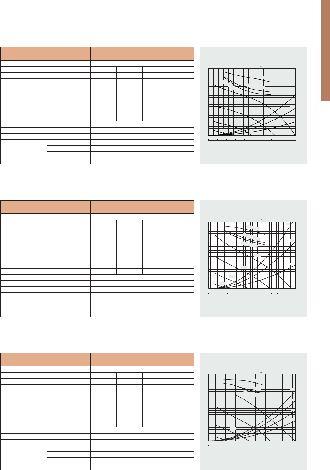
168
Unit: mm
LGH-200RVXT-E
Fan speed
Supply voltage
(V)
220
230
240
220
Power line frequency
(Hz)
50
50
50
60
Temp. exchange
eciency
(%)
Power consumption
(W)
Noise
(dB)
Air volume
(
m
3
/h
)
Weight
(kg)
73
80
73
80
72
79
73
80
HI
LO
HI
LO
HI
LO
HI
LO
30
13
31
15
34
17
34
17
36.5
24
37
25
38
27
38
25
100
55
105
60
106
61
103
57
7.5
226
12
FRONT PANEL
(OPEN POSITION)
FRONT PANEL LOUVER
(HORIZONTAL POSITION)
FRONT PANEL LOUVER
(VERTICAL POSITION)
FRONT PANEL
(CLOSED POSITION)
EDGE OF MAIN UNIT
420
REQUIRE TO BE SECURED
REQUIRE TO BE SECURED
ABLE)
(ADJUST
(ADJUSTABLE)
AIR INTAKE HOLE
ø85 to ø90 WALL HOLE
40
108
11995
25
15
95.5
PITCH 20X10=200
265
13.5238.5
183min
from nearest
obstruction
233min
75
87
267.5
554
292
75
(ADJUST
ABLE)
MOUNTING HOLES
36×ø6
530
360min from nearest obstruction
200(MIN)
350(MAX)
360min
620
AIR EXHAUST HOLE
ø85 to ø90 WALL HOLE
OUTER DIA
OUTER DIA
ø75×2
ø79×2
SHUTTER KNOB
WALL THICKNESS
SHUTTER KNOB
FRESH AIR SUPPLY
90 140
620
54
200
5°
ø150
106
50 to 550
22
17
9725
POWER CORD HOLE
(CLOSED POSITION) (OPEN POSITION)
INDOOR AIR EXHAUST
MOUNTING PLATE
Unit: mm
LGH-250RVXT-E
Fan speed
Supply voltage
(V)
220
230
240
220
Power line frequency
(Hz)
50
50
50
60
Temp. exchange
eciency
(%)
Power consumption
(W)
Noise
(dB)
Air volume
(
m
3
/h
)
Weight
(kg)
73
80
73
80
72
79
73
80
HI
LO
HI
LO
HI
LO
HI
LO
30
13
31
15
34
17
34
17
36.5
24
37
25
38
27
38
25
100
55
105
60
106
61
103
57
7.5
226
12
FRONT PANEL
(OPEN POSITION)
FRONT PANEL LOUVER
(HORIZONTAL POSITION)
FRONT PANEL LOUVER
(VERTICAL POSITION)
FRONT PANEL
(CLOSED POSITION)
EDGE OF MAIN UNIT
420
REQUIRE TO BE SECURED
REQUIRE TO BE SECURED
ABLE)
(ADJUST
(ADJUSTABLE)
AIR INTAKE HOLE
ø85 to ø90 WALL HOLE
40
108
11995
25
15
95.5
PITCH 20X10=200
265
13.5238.5
183min
from nearest
obstruction
233min
MOUNTING PLATE
75
87
267.5
554
292
75
(ADJUST
ABLE)
MOUNTING HOLES
36×ø6
530
360min from nearest obstruction
200(MIN)
350(MAX)
360min
620
AIR EXHAUST HOLE
ø85 to ø90 WALL HOLE
OUTER DIA
OUTER DIA
ø75×2
ø79×2
175
SHUTTER KNOB
WALL THICKNESS
SHUTTER KNOB
FRESH AIR SUPPLY
252
90 140
620
54
200
5°
ø150
106
50 to 550
22
17
(OPEN POSITION)
INDOOR AIR EXHAUST
(CLOSED POSITION)
020406080100 120140 160220 240260180200
60
70
80
90
0
50
100
150
300
350
200
250
0100 200 1000400300500 600800 900700
Exchange efficiency (%)
Static pressure (Pa)
Air volume
(m
3
/h)
SP1
SP2
SP3
SP4
200mm dia straight pipe length
Temperatur
e
E
n
thal
py
h
ea
t
i
ng
En
t
halpy cool
i
n
g
(L/s)
20m
40m
60m
20m
60m
40m
020406080100 120 140 160 180
60
70
80
90
0
50
100
150
200
300
250
0100 200 700400300 600500
Exchange efficiency (%)
Static pressure (Pa)
Air volume
(m
3
/h)
SP1
SP2
SP3
SP4
200mm dia straight pipe length
Temperatur
e
Enthalpy heatin
g
Enthal
p
y co
o
lin
g
(L/s)
40m
60m
80m
100m
050100 150200 250 350300
60
70
80
90
0
50
100
150
300
350
200
250
0 800 1000600 1200200400
Exchange efficiency (%)
Static pressure (Pa)
Air volume
(m
3
/h)
SP1
SP2
SP3
SP4
250mm dia straight pipe length
Tem
pera
tur
e
Entha
l
py he
a
t
i
ng
Enth
alpy
c
o
oling
(L/s)
MODEL
LGH-80RVX-E
Electrical power supply V/Phase/Hz
220-240 / 1 /50
Fan Speed
SP4 SP3 SP2 SP1
Running current A
1,82-1,97 0,83-0,86 0,36-0,40 0,15-0,16
Power input W
335-340 151 60-64 18-20
Air Volume m³/h
800 600 400 200
External static pressure
Pa
150 85 37,5 10
Exchange temperature efficiency %
79,0 82,5 84,0 85,0
Exchange enthalpy
efficiency
Cooling %
70,0 72,5 78,0 81,0
Heating %
71,0 73,5 78,0 81,0
Sound pressure level dB(A)
34,5-36,0 30,0 23 18
Ducts: Nr. diameter mm
4 x 250
Weight kg
48
Dimensions AxLxP mm
404x1004x1144
"Guaranteed Opera-
ting Range
(Continuous operation)”
T. ext °C
-10 ~ +40
UR ext max %
80
T. int max °C
40
UR int max %
80
MODEL
LGH-65RVX-E
Electrical power supply V/Phase/Hz
220-240 / 1 /50
Fan Speed
SP4 SP3 SP2 SP1
Running current A
1,65-1,72 0,90-0,86 0,39-0,38 0,15-0,16
Power input W
252-262 131 49-47 15-17
Air Volume m³/h
650 488 325 163
External static pressure
Pa
120 68 30 8
Exchange temperature efficiency %
77,0 81,0 84,0 86,0
Exchange enthalpy
efficiency
Cooling %
66,0 69,5 74,0 81,0
Heating %
68,5 71,0 76,0 82,0
Sound pressure level dB(A)
34,5-35,5 29 22 18
Ducts: Nr. diameter mm
4 x 200
Weight kg
38
Dimensions AxLxP mm
404x954x908
"Guaranteed
Operating Range
(Continuous operation)”
T. ext °C
-10 ~ +40
UR ext max %
80
T. int max °C
40
UR int max %
80
MODEL
LGH-50RVX-E
Electrical power supply V/Phase/Hz
220-240 / 1 /50
Fan Speed
SP4 SP3 SP2 SP1
Running current A
1,15 0,59 0,26-0,27 0,13
Power input W
165-173 78-81 32-35 12-14
Air Volume m³/h
500 375 250 125
External static pressure
Pa
120 68 30 8
Exchange temperature efficiency %
78,0 81,0 83,5 87,0
Exchange enthalpy
efficiency
Cooling %
66,5 68,0 72,5 82,0
Heating %
69,0 71,0 75,0 82,5
Sound pressure level dB(A)
34-35 28-29 19-20 18
Ducts: Nr. diameter mm
4 x 200
Weight kg
33
Dimensions AxLxP mm
331x1016x888
"Guaranteed Opera-
ting Range
(Continuous operation)”
T. ext °C
-10 ~ +40
UR ext max %
80
T. int max °C
40
UR int max %
80
Specifications
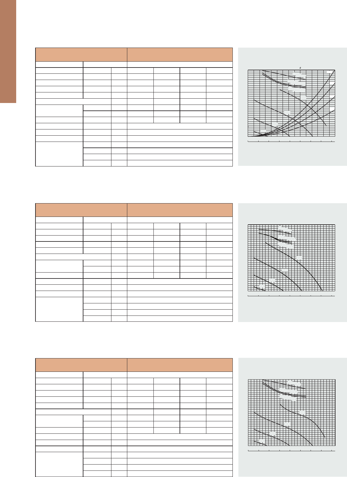
Unit: mm
VL-100EU5-E
Fan speed
Supply voltage
(V)
220
230
240
220
Power line frequency
(Hz)
50
50
50
60
Temp. exchange
eciency
(%)
Power consumption
(W)
Noise
(dB)
Air volume
(
m
3
/h
)
Weight
(kg)
73
80
73
80
72
79
73
80
HI
LO
HI
LO
HI
LO
HI
LO
30
13
31
15
34
17
34
17
36.5
24
37
25
38
27
38
25
100
55
105
60
106
61
103
57
7.5
226
12
FRONT PANEL
(OPEN POSITION)
FRONT PANEL LOUVER
(HORIZONTAL POSITION)
FRONT PANEL LOUVER
(VERTICAL POSITION)
FRONT PANEL
(CLOSED POSITION)
EDGE OF MAIN UNIT
420
REQUIRE TO BE SECURED
REQUIRE TO BE SECURED
ABLE)
(ADJUST
(ADJUSTABLE)
AIR INTAKE HOLE
ø85 to ø90 WALL HOLE
40
108
11995
25
15
95.5
PITCH 20X10=200
265
13.5238.5
183min
from nearest
obstruction
233min
75
87
267.5
554
292
75
(ADJUST
ABLE)
MOUNTING HOLES
36×ø6
530
360min from nearest obstruction
200(MIN)
350(MAX)
360min
620
AIR EXHAUST HOLE
ø85 to ø90 WALL HOLE
OUTER
DI
A
OUTER DIA
ø
7
5×
2
ø
79×2
SHUTTER KNOB
WALL THICKNESS
SHUTTER KNOB
FRESH AIR SUPPLY
90 140
620
54
200
5°
ø150
106
50 to 550
22
17
9725
POWER CORD HOLE
(CLOSED POSITION) (OPEN POSITION)
INDOOR AIR EXHAUST
MOUNTING PLATE
Unit: mm
VL-22ECZGV-E
Fan speed
Supply voltage
(V)
220
230
240
220
Power line frequency
(Hz)
50
50
50
60
Temp. exchange
eciency
(%)
Power consumption
(W)
Noise
(dB)
Air volume
(
m
3
/h
)
Weight
(kg)
73
80
73
80
72
79
73
80
HI
LO
HI
LO
HI
LO
HI
LO
30
13
31
15
34
17
34
17
36.5
24
37
25
38
27
38
25
100
55
105
60
106
61
103
57
7.5
226
12
FRONT PANEL
(OPEN POSITION)
FRONT PANEL LOUVER
(HORIZONTAL POSITION)
FRONT PANEL LOUVER
(VERTICAL POSITION)
FRONT PANEL
(CLOSED POSITION)
EDGE OF MAIN UNIT
420
REQUIRE TO BE SECURED
REQUIRE TO BE SECURED
ABLE)
(ADJUST
(ADJUSTABLE)
AIR INTAKE HOLE
ø85 to ø90 WALL HOLE
40
108
95
PITCH 20X10=200
265
13.5238.5
183min
from nearest
obstruction
233min
MOUNTING PLATE
75
87
267.5
554
292
75
(ADJUST
ABLE)
MOUNTING HOLES
36×ø6
530
360min from nearest obstruction
200(MIN)
350(MAX)
360min
620
AIR EXHAUST HOLE
ø85 to ø90 WALL HOLE
O
UTER D
IA
OUTER DIA
ø75×
2
ø7
9
×2
175
SHUTTER KNOB
WALL THICKNESS
SHUTTER KNOB
FRESH AIR SUPPLY
252
90 140
620
54
200
5°
ø150
106
50 to 550
22
17
(OPEN POSITION)
INDOOR AIR EXHAUST
(CLOSED POSITION)
F
an spee
d
Suppl
y
voltag
e
(
V
)
220
23
0
24
0
22
0
Power line frequenc
y
(
Hz
)
50
5
0
5
0
6
0
T
emp. exchang
e
e
cienc
y
(
%
)
P
ower consumptio
n
(
W
)
No
i
s
e
(
d
B
)
Air vo
l
ume
(
m
3
/
h
)
Weig
ht
(k
g
)
7
3
80
7
3
80
72
7
9
73
80
HI
LO
HI
LO
HI
L
O
HI
LO
30
13
3
1
15
3
4
17
34
17
36.5
24
3
7
25
38
27
3
8
25
100
5
5
10
5
6
0
106
6
1
1
03
5
7
7
.
5
EDGE
O
F MAIN UNIT
420
RE
Q
UIRE TO BE SECURE
D
RE
Q
UIRE TO BE SECURED
ABLE)
(ADJUST
(
ADJUSTABLE
)
AIR INTAKE H
O
L
E
ø
85 to
ø
90 WALL HOL
E
40
108
9
5
PITCH 20X10=200
2
65
13
.
5
2
38
.
5
183
min
from neare
st
obstruction
2
33
min
MO
UNTING PLATE
7
5
8
7
267.
5
554
292
7
5
(ADJUST
ABLE)
MOUNTING HOLE
S
36
×
ø6
530
200(MIN)
350(MAX)
(
6
20
AIR EXHAUST H
O
LE
ø
85 to
ø
90 WALL HOL
E
Specications / Dimensions
169
40m
60m
80m
100m
050100 15025020
04
00350300
60
70
80
90
0
50
100
150
300
350
200
250
0500 15001000
Exchange efficiency (%)
Static pressure (Pa)
Air volume
(m
3
/h)
SP1
SP2
SP3
SP4
250mm dia straight pipe length
Temp
e
r
at
ur
e
Enthalpy heating
Enthalpy
coolin
g
(L/s)
0100 200300 400500 600700 800
60
70
80
90
0
50
100
150
300
350
200
250
010005001500200
03
0002500
Exchange efficiency (%)
Static pressure (Pa)
Air volume
(m
3
/h)
SP1
SP2
SP3
SP4
Te
mperature
E
nthalpy
heat
in
g
Enthalpy coo
ling
(L/s)
0100 200300 400500 600700 800
60
70
80
90
0
50
100
150
200
300
350
250
0500 1000 1500 2000 2500 3000
Exchange efficiency (%)
Static pressure (Pa)
Air volume
(m
3
/h)
SP1
SP2
SP3
SP4
Tem
perature
Enthalpy
h
ea
ting
En
th
a
l
py cooli
ng
(L/s)
MODEL
LGH-200RVX-E
Electrical power supply V/Phase/Hz
220-240 / 1 /50
Fan Speed
SP4 SP3 SP2 SP1
Running current A
4,88-4,54 2,20-2,06 0,88-0,87 0,33-0,35
Power input W
850-853 400-372 153-150 42-49
Air Volume m³/h
2000 1500 1000 500
External static pressure
Pa
150 84,4 37,5 9,5
Exchange temperature efficiency %
80,0 83,0 86,5 89,5
Exchange enthalpy
efficiency
Cooling %
71,0 73,0 77,0 85,5
Heating %
72,5 74,0 78,0 87,0
Sound pressure level dB(A)
40-41 36 28-27 18-19
Ducts: Nr. diameter mm
4 x 250 / 2 x (270x700)
Weight kg
110
Dimensions AxLxP mm
808x1231x1144
“Guaranteed
Operating Range
(Continuous operation)”
T. ext °C
-10 ~ +40
UR ext max %
80
T. int max °C
40
UR int max %
80
MODEL
LGH-150RVX-E
Electrical power supply V/Phase/Hz
220-240 / 1 /50
Fan Speed
SP4 SP3 SP2 SP1
Running current A
3,71-3,85 1,75-1,78 0,70-0,78 0,29-0,30
Power input W
670-698 311 123-124 38-44
Air Volume m³/h
1500 112 5 750 375
External static pressure
Pa
175 98,4 43,8 10,9
Exchange temperature efficiency %
80,0 82,5 84,0 85,0
Exchange enthalpy
efficiency
Cooling %
70,5 72,5 78,0 81,0
Heating %
72,0 73,5 78,0 81,0
Sound pressure level dB(A)
39,0-40,5 32-33 24-26 18
Ducts: Nr. diameter mm
4 x 250 / 2 x (270x700)
Weight kg
98
Dimensions AxLxP mm
808x1004x1144
“Guaranteed
Operating Range
(Continuous operation)”
T. ext °C
-10 ~ +40
UR ext max %
80
T. int max °C
40
UR int max %
80
MODEL
LGH-100RVX-E
Electrical power supply V/Phase/Hz
220-240 / 1 /50
Fan Speed
SP4 SP3 SP2 SP1
Running current A
2,50 1,20 0,50-0,51 0,17-0,19
Power input W
420 200 75 21
Air Volume m³/h
1000 750 500 250
External static pressure
Pa
170 95,6 42,5 10,6
Exchange temperature efficiency %
80,0 83,0 86,5 89,5
Exchange enthalpy
efficiency
Cooling %
71,0 73,0 77,0 85,5
Heating %
72,5 74,0 78,0 87,0
Sound pressure level dB(A)
37-38 31-32 23-24 18
Ducts: Nr. diameter mm
4 x 250
Weight kg
54
Dimensions AxLxP mm
404x1231x1144
"Guaranteed
Operating Range
(Continuous operation)”
T. ext °C
-10 ~ +40
UR ext max %
80
T. int max °C
40
UR int max %
80
Specifications
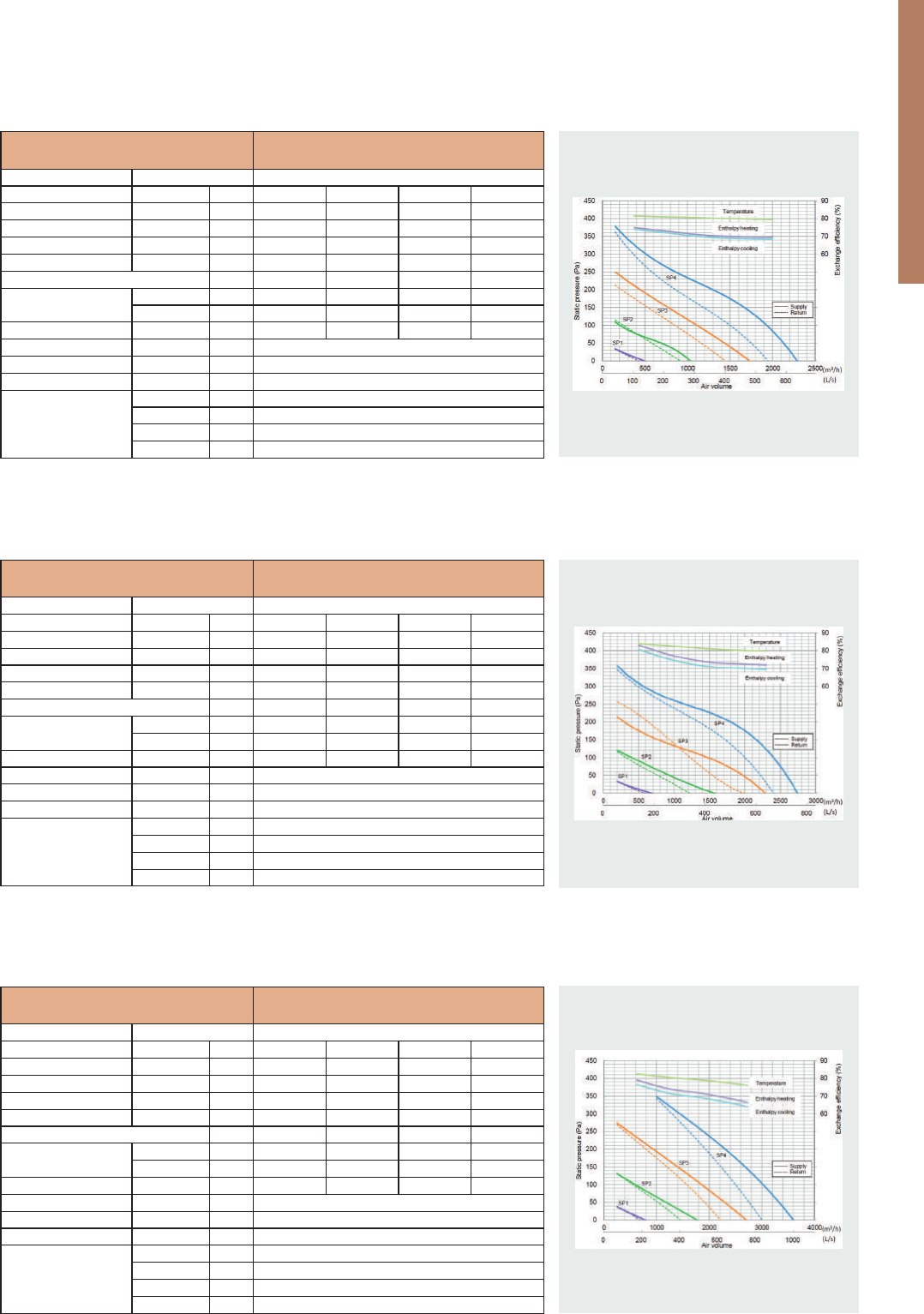
170
Unit: mm
LGH-200RVXT-E
Fan speed
Supply voltage
(V)
220
230
240
220
Power line frequency
(Hz)
50
50
50
60
Temp. exchange
eciency
(%)
Power consumption
(W)
Noise
(dB)
Air volume
(
m
3
/h
)
Weight
(kg)
73
80
73
80
72
79
73
80
HI
LO
HI
LO
HI
LO
HI
LO
30
13
31
15
34
17
34
17
36.5
24
37
25
38
27
38
25
100
55
105
60
106
61
103
57
7.5
226
12
FRONT PANEL
(OPEN POSITION)
FRONT PANEL LOUVER
(HORIZONTAL POSITION)
FRONT PANEL LOUVER
(VERTICAL POSITION)
FRONT PANEL
(CLOSED POSITION)
EDGE OF MAIN UNIT
420
REQUIRE TO BE SECURED
REQUIRE TO BE SECURED
ABLE)
(ADJUST
(ADJUSTABLE)
AIR INTAKE HOLE
ø85 to ø90 WALL HOLE
40
108
11995
25
15
95.5
PITCH 20X10=200
265
13.5238.5
183min
from nearest
obstruction
233min
75
87
267.5
554
292
75
(ADJUST
ABLE)
MOUNTING HOLES
36×ø6
530
360min from nearest obstruction
200(MIN)
350(MAX)
360min
620
AIR EXHAUST HOLE
ø85 to ø90 WALL HOLE
OUTER DIA
OUTER DIA
ø75×2
ø79×2
SHUTTER KNOB
WALL THICKNESS
SHUTTER KNOB
FRESH AIR SUPPLY
90 140
620
54
200
5°
ø150
106
50 to 550
22
17
9725
POWER CORD HOLE
(CLOSED POSITION) (OPEN POSITION)
INDOOR AIR EXHAUST
MOUNTING PLATE
Unit: mm
LGH-250RVXT-E
Fan speed
Supply voltage
(V)
220
230
240
220
Power line frequency
(Hz)
50
50
50
60
Temp. exchange
eciency
(%)
Power consumption
(W)
Noise
(dB)
Air volume
(
m
3
/h
)
Weight
(kg)
73
80
73
80
72
79
73
80
HI
LO
HI
LO
HI
LO
HI
LO
30
13
31
15
34
17
34
17
36.5
24
37
25
38
27
38
25
100
55
105
60
106
61
103
57
7.5
226
12
FRONT PANEL
(OPEN POSITION)
FRONT PANEL LOUVER
(HORIZONTAL POSITION)
FRONT PANEL LOUVER
(VERTICAL POSITION)
FRONT PANEL
(CLOSED POSITION)
EDGE OF MAIN UNIT
420
REQUIRE TO BE SECURED
REQUIRE TO BE SECURED
ABLE)
(ADJUST
(ADJUSTABLE)
AIR INTAKE HOLE
ø85 to ø90 WALL HOLE
40
108
11995
25
15
95.5
PITCH 20X10=200
265
13.5238.5
183min
from nearest
obstruction
233min
MOUNTING PLATE
75
87
267.5
554
292
75
(ADJUST
ABLE)
MOUNTING HOLES
36×ø6
530
360min from nearest obstruction
200(MIN)
350(MAX)
360min
620
AIR EXHAUST HOLE
ø85 to ø90 WALL HOLE
OUTER DIA
OUTER DIA
ø75×2
ø79×2
175
SHUTTER KNOB
WALL THICKNESS
SHUTTER KNOB
FRESH AIR SUPPLY
252
90 140
620
54
200
5°
ø150
106
50 to 550
22
17
(OPEN POSITION)
INDOOR AIR EXHAUST
(CLOSED POSITION)
MODEL
LGH-250RVXT-E
Electrical power supply V/Phase/Hz
220-240 / 1 /50
Fan Speed
SP4 SP3 SP2 SP1
Running current A
7,60 - 6,90 3,60 - 3,10 1,40 - 1,30 0,57 - 0,49
Power input W
1446 - 1298 687 - 587 244 - 212 82 - 69
Air Volume m³/h
2500 1875 1250 625
External static pressure
Pa
175 98 44 11
Exchange temperature efficiency %
77,0 79,0 80,5 82,5
Exchange enthalpy
efficiency
Cooling %
65,5 69,0 71,5 76,5
Heating %
68,0 71,5 74,0 79,0
Sound pressure level dB(A)
43,0 39,0 32,0 24,0
Ducts: Nr. diameter mm
4 x 250 / 2 x (250x750)
Weight kg
198
Dimensions AxLxP mm
500 x 1980 x 1500
“Guaranteed
Operating Range
(Continuous operation)”
T. ext °C
-10 ~ +40
UR ext max %
80
T. int max °C
40
UR int max %
80
MODEL
LGH-200RVXT-E
Electrical power supply V/Phase/Hz
220-240 / 1 /50
Fan Speed
SP4 SP3 SP2 SP1
Running current A
5,40 - 5,00 2,70 - 2,20 1,10 - 0,85 0,39 - 0,34
Power input W
1000 - 916 494 - 407 197 - 150 56 - 45
Air Volume m³/h
2000 1500 1000 500
External static pressure
Pa
175 98 44 11
Exchange temperature efficiency %
80,0 81,0 82,5 84,0
Exchange enthalpy
efficiency
Cooling %
70,0 71,0 74,5 80,5
Heating %
72,5 73,5 77,0 83,0
Sound pressure level dB(A)
39,5 35,5 28,0 22,0
Ducts: Nr. diameter mm
4 x 250 / 2 x (250x750)
Weight kg
159
Dimensions AxLxP mm
500 x 1980 x 1500
“Guaranteed
Operating Range
(Continuous operation)”
T. ext °C
-10 ~ +40
UR ext max %
80
T. int max °C
40
UR int max %
80
MODEL
LGH-150RVXT-E
Electrical power supply V/Phase/Hz
220-240 / 1 /50
Fan Speed
SP4 SP3 SP2 SP1
Running current A
4,30 - 3,40 2,40 - 1,80 1,10 - 0,77 0,36 - 0,31
Power input W
792 - 625 421 - 334 176 - 134 48 - 37
Air Volume m³/h
1500 112 5 750 375
External static pressure
Pa
175 98 44 11
Exchange temperature efficiency %
80,0 80,5 81,0 81,5
Exchange enthalpy
efficiency
Cooling %
69,0 70,0 72,0 74,0
Heating %
70,0 71,0 73,0 75,0
Sound pressure level dB(A)
39,5 35,5 29,5 22,0
Ducts: Nr. diameter mm
4 x 250 / 2 x (250x750)
Weight kg
156
Dimensions AxLxP mm
500 x 1980 x 1500
“Guaranteed
Operating Range
(Continuous operation)”
T. ext °C
-10 ~ +40
UR ext max %
80
T. int max °C
40
UR int max %
80
Specifications
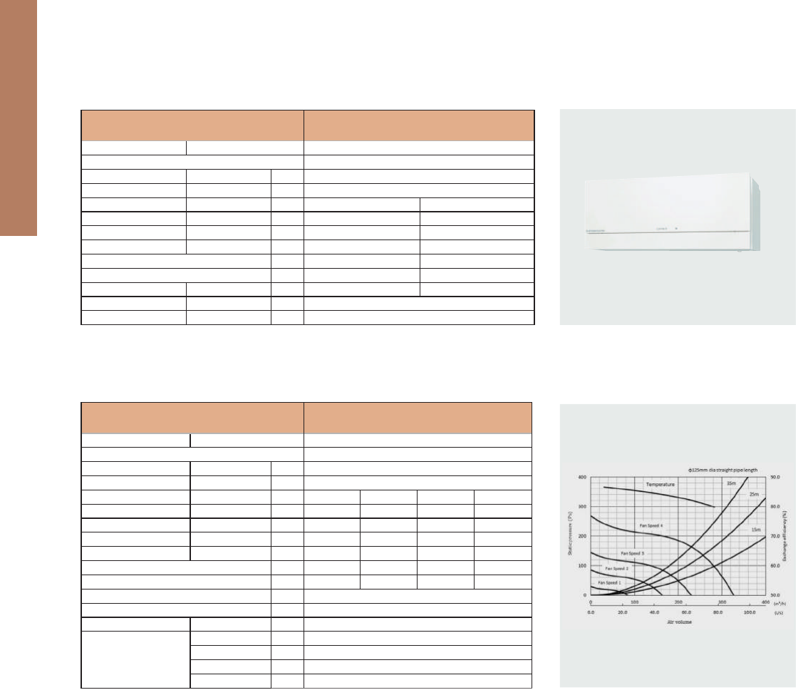
Unit: mm
VL-100EU5-E
Fan speed
Supply voltage
(V)
220
230
240
220
Power line frequency
(Hz)
50
50
50
60
Temp. exchange
eciency
(%)
Power consumption
(W)
Noise
(dB)
Air volume
(
m
3
/h
)
Weight
(kg)
73
80
73
80
72
79
73
80
HI
LO
HI
LO
HI
LO
HI
LO
30
13
31
15
34
17
34
17
36.5
24
37
25
38
27
38
25
100
55
105
60
106
61
103
57
7.5
226
12
FRONT PANEL
(OPEN POSITION)
FRONT PANEL LOUVER
(HORIZONTAL POSITION)
FRONT PANEL LOUVER
(VERTICAL POSITION)
FRONT PANEL
(CLOSED POSITION)
EDGE OF MAIN UNIT
420
REQUIRE TO BE SECURED
REQUIRE TO BE SECURED
ABLE)
(ADJUST
(ADJUSTABLE)
AIR INTAKE HOLE
ø85 to ø90 WALL HOLE
40
108
11995
25
15
95.5
PITCH 20X10=200
265
13.5238.5
183min
from nearest
obstruction
233min
75
87
267.5
554
292
75
(ADJUST
ABLE)
MOUNTING HOLES
36×ø6
530
360min from nearest obstruction
200(MIN)
350(MAX)
360min
620
AIR EXHAUST HOLE
ø85 to ø90 WALL HOLE
OUTER
DI
A
OUTER DIA
ø
7
5×
2
ø
79×2
SHUTTER KNOB
WALL THICKNESS
SHUTTER KNOB
FRESH AIR SUPPLY
90 140
620
54
200
5°
ø150
106
50 to 550
22
17
9725
POWER CORD HOLE
(CLOSED POSITION) (OPEN POSITION)
INDOOR AIR EXHAUST
MOUNTING PLATE
Unit: mm
VL-22ECZGV-E
Fan speed
Supply voltage
(V)
220
230
240
220
Power line frequency
(Hz)
50
50
50
60
Temp. exchange
eciency
(%)
Power consumption
(W)
Noise
(dB)
Air volume
(
m
3
/h
)
Weight
(kg)
73
80
73
80
72
79
73
80
HI
LO
HI
LO
HI
LO
HI
LO
30
13
31
15
34
17
34
17
36.5
24
37
25
38
27
38
25
100
55
105
60
106
61
103
57
7.5
226
12
FRONT PANEL
(OPEN POSITION)
FRONT PANEL LOUVER
(HORIZONTAL POSITION)
FRONT PANEL LOUVER
(VERTICAL POSITION)
FRONT PANEL
(CLOSED POSITION)
EDGE OF MAIN UNIT
420
REQUIRE TO BE SECURED
REQUIRE TO BE SECURED
ABLE)
(ADJUST
(ADJUSTABLE)
AIR INTAKE HOLE
ø85 to ø90 WALL HOLE
40
108
95
PITCH 20X10=200
265
13.5238.5
183min
from nearest
obstruction
233min
MOUNTING PLATE
75
87
267.5
554
292
75
(ADJUST
ABLE)
MOUNTING HOLES
36×ø6
530
360min from nearest obstruction
200(MIN)
350(MAX)
360min
620
AIR EXHAUST HOLE
ø85 to ø90 WALL HOLE
O
UTER D
IA
OUTER DIA
ø75×
2
ø7
9
×2
175
SHUTTER KNOB
WALL THICKNESS
SHUTTER KNOB
FRESH AIR SUPPLY
252
90 140
620
54
200
5°
ø150
106
50 to 550
22
17
(OPEN POSITION)
INDOOR AIR EXHAUST
(CLOSED POSITION)
F
an spee
d
Suppl
y
voltag
e
(
V
)
220
23
0
24
0
22
0
Power line frequenc
y
(
Hz
)
50
5
0
5
0
6
0
T
emp. exchang
e
e
cienc
y
(
%
)
P
ower consumptio
n
(
W
)
No
i
s
e
(
d
B
)
Air vo
l
ume
(
m
3
/
h
)
Weig
ht
(k
g
)
7
3
80
7
3
80
72
7
9
73
80
HI
LO
HI
LO
HI
L
O
HI
LO
30
13
3
1
15
3
4
17
34
17
36.5
24
3
7
25
38
27
3
8
25
100
5
5
10
5
6
0
106
6
1
1
03
5
7
7
.
5
EDGE
O
F MAIN UNIT
420
RE
Q
UIRE TO BE SECURE
D
RE
Q
UIRE TO BE SECURED
ABLE)
(ADJUST
(
ADJUSTABLE
)
AIR INTAKE H
O
L
E
ø
85 to
ø
90 WALL HOL
E
40
108
9
5
PITCH 20X10=200
2
65
13
.
5
2
38
.
5
183
min
from neare
st
obstruction
2
33
min
MO
UNTING PLATE
7
5
8
7
267.
5
554
292
7
5
(ADJUST
ABLE)
MOUNTING HOLE
S
36
×
ø6
530
200(MIN)
350(MAX)
(
6
20
AIR EXHAUST H
O
LE
ø
85 to
ø
90 WALL HOL
E
Specications / Dimensions
171
VL-220CZGV-E
220-240 / MONOFASE /50
A (-37,0)
260
44
SP4 SP3 SP2 SP1
0,60 0,29 0,18 0,11
80 35 18,5 8,5
230 165 120 65
164 84 44 13
82 84 85 86
31,0 25,0 19,0 14,0
4 x 100
31
320x885x815
-15 ~ +40
80
40
95
VL-100EU
5
-E
220-240 / 1 / 50
B (-28,8)
100
52
Alta Bassa
- -
31 15
105 60
- -
73 80
37 25
7, 5
265x620x200
1
According to 1254/2014 regulation
1
According to 1254/2014 regulation
MODELLO
Electrical power supply V/Phase/Hz
Energy Efficiency Class (S.E.C.)
ErP
1
Data Flow rate max m
3
/h
Sound power level max
dB(A)
Fan Speed
Running current A
Power input W
Air Volume m
3
/h
External static pressure Pa
Exchange temperature efficiency %
Sound pressure level dB(A)
Ducts: Nr, diameter mm
Weight
kg
Dimensions AxLxP mm
Guaranteed Operating
Range
(Continuous operation)*
T. ext °C
UR ext max %
T. int max °C
UR int max %
Specifications
MODELLO
Electrical power supply V/Phase/Hz
Energy Efficiency Class (S.E.C.)
ErP
1
Data Flow rate max m
3
/h
Sound power level max
dB(A)
Fan Speed
Running current A
Power input W
Air Volume m
3
/h
External static pressure Pa
Exchange temperature efficiency %
Sound pressure level dB(A)
Weight kg
Dimensions HxWxD mm
SPLIT-TYPE AIR CONDITIONERS Full Product Line Catalogue 2015
Wrap Yourself in Comfort and Quiet
Eco-conscious Technologies from Japan
Full Product Line Catalogue
2016
TENTATIVE
NOTICE
■ Do not install indoor units in areas (e.g. mobile phone base stations) where the emission of VOCs such as phthalate
compounds and formaldehyde is known to be high as this may result in a chemical reaction.
■ Our air-conditioning equipment and heat pumps contain a fluorinated greenhouse gas, R410A.
■ When installing or relocating or servicing our air-conditioning equipment, use only the specified refrigerant
(
R410A
)
to charge
the refrigerant lines.
Do not mix it with any other refrigerant and do not allow air to remain in the lines.
If air is mixed with the refrigerant, then it can be the cause of abnormal high pressure in the refrigerant lines, and may result
in an explosion and other hazards.
The use of any refrigerant other than that specified for the system will cause mechanical failure, system malfunction or unit
breakdown. In the worst case, this could lead to a serious impediment to securing product safety.
Eco Changes is the Mitsubishi Electric Group’s environmental statement,
and expresses the Group’s stance on environmental management.
Through a wide range of businesses, we are helping contribute to the
realization of a sustainable society.
S-179-5-C9521-C SI1511 Printed in Japan (IP)
Revised Publication, effective Nov. 2015.
Superseding Publication, S-179-5-C9521-B of Apr. 2015.
Specifications are subject to change without notice.