PRODUCT
CATA LOG
08.15
ENERGY-INTELLIGENT
™
HEATING AND COOLING SYSTEMS
Setting Daikin's new standards in
indoor comfort and efficiency

Overview 2
Why choose Daikin? 3
What is Daikin VRV? 4
Why choose Daikin VRV? 5
Which VRV system offers the best solution? 6
Setting the standards 8
Daikin VRV IV 10
Setting the standards, again 10
What does a VRV installation mean to you? 22
Vertical market applications 24
Product Portfolio 26
Outdoor units 28
Indoor units 30
Accessories 32
Indoor units 38
Indoor units overview 42
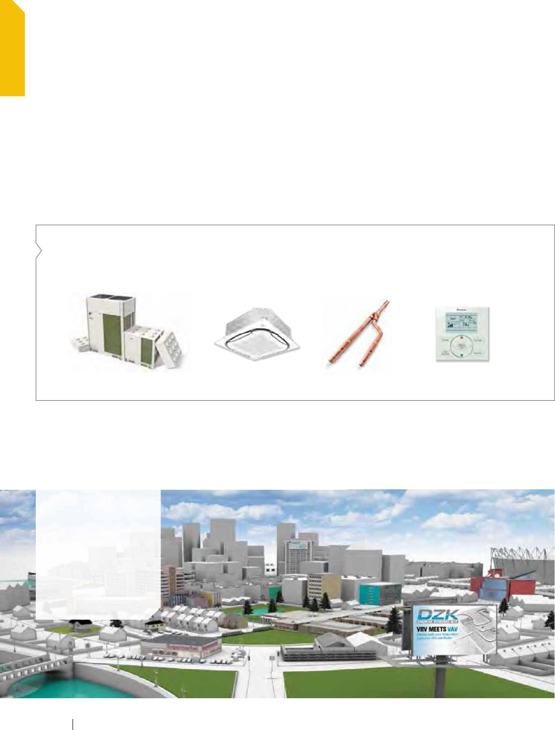
FXMQ-PBVJU - DC-Ducted Concealed Ceiling Unit 44
(Medium Static) and DZK
FXDQ-MVJU - Slim-Duct, Built-In Concealed Ceiling Unit 48
FXTQ-PAVJU - Vertical Air Handling Unit 50
FXMQ-MVJU - Concealed Ceiling Unit (Medium Static) 52
FXNQ-MVJU9 - Concealed Floor-Standing Unit 54
FXFQ-TVJU - Round Flow Sensing Cassette 56
FXUQ-PVJU - 4-Way Ceiling-Suspended Cassette 60
FXZQ-MVJU9 - 2'x2' 4-Way Ceiling-Mounted Cassette 62
FXEQ-PVJU - Ceiling-Mounted Cassette 64
FXHQ-MVJU - Ceiling-Suspended Unit 66
FXAQ-PVJU - Wall-Mounted Unit 68
FXLQ-MVJU9 - Floor-Standing Unit 70
Outdoor units 72
VRV IV - Air-Cooled Heat Recovery 76
VRV IV - Air-Cooled Heat Pump 80
VRV III PC - Air-Cooled Heat Recovery 84
VRV IV W-Series - Heat Pump or Heat Recovery 86
VRV IV W-Series - Single Module System 208-230V 88
VRV IV W-Series - Double Module System 208-230V 89
VRV IV W-Series - Triple Module System 208-230V 90
VRV IV W-Series - Single Module System 460V 91
VRV IV W-Series - Double Module System 460V 92
VRV IV W-Series - Triple Module System 460V 93
VRV III-S - Heat Pump 208-230V 94
VRV IV, VRV III PC, VRV IV W-Series, & VRV III-S 96
- installation space
VRV IV, VRV III PC, VRV IV W-Series, & VRV III-S 100
- piping length
VRV Accessories 102
Branch Selector boxes 102
REFNET pipe joints 104
Hail Guard Kit for VRV IV 105
Ventilation 106
FXMQ-MFVJU - 100% Outside Air Processing Unit 110
VAM-GVJU - Energy Recovery Ventilator 112
Controls 114
VRV controls matrix 116
VRV control systems 118
Individual controllers 120
BRC1E73 - Navigation Remote Controller 120
BRC4C82/BRC7E818/BRC7E83/BRC7E830 126
Wireless Remote Controller
BRC2A71 - Simplified Remote Controller 126
Centralized controllers 128
DCS302C71 - Central Remote Controller 128
DCS301C71 - Unified On/Off Controller 129
DST301BA61 - Schedule Timer 129
Advanced multi-zone controllers 130
DCM601A71 - intelligent Touch Manager (iTM) 130
DCS601C71 - intelligent Touch Controller (iTC) 132
Open protocol interfaces 134
Interface for BACnet
®
, LonWorks
®
and Modbus 134
VRV monitoring services 135
D-NET Air Conditioning Network Service System 135
Option list 136
Individual zone controllers 136
Centralized controllers 136
Advanced multi-zone controllers 136
Open protocol interface 136
Adapters 137
WAGO 137
Support and Tools 138
Support and tools overview 141
Selection software 142
Energy screening and simulation tools 142
Design and verification 143
Online and tablet reference material 143
Smartphone and mobile reference 144
After sales and service 145
1
PRODUCT PORTFOLIO INDOOR UNITS OUTDOOR UNITSOVERVIEW CONTROLS SUPPORT & TOOLSVENTILATION
Table of contents

www.daikincomfort.com2
OVERVIEW

Why choose Daikin?
Inverter
Contributes to greater
energy savings and comfort
Heat pump
Absorbs or removes
heat from the air
Refrigerant control
Efficient heat transport
DAIKIN
CORE
TECHNOLOGY
A history of industry-leading
product innovation
Becoming a global leader in any industry takes more than just
time. For over 90 years Daikin has shown that it takes industry-
leading product innovation and a commitment to excellence in
order to climb to the top. This commitment led Daikin to develop
the first Variable Refrigerant Volume (VRV) system in 1982 and to
become a pioneer with our Variable Refrigerant Volume systems.
Daikin’s 3 core technologies
Daikin is an industry-leading HVAC technology company.
We develop state-of-the-art technology that provides indoor
comfort solutions for our customers. We do this by focusing
on 3 core technologies. Our refrigerant control technology
provides an efficient and effective way to transport heat. Daikin
inverter technology allows us to maximize energy efficiency and
heat pump technology provides an effective method for
moving refrigerant.
The total solution
Daikin’s products and controls are designed to provide a flexible,
scalable, total indoor comfort solution. We are committed to
supporting our customers at every phase of the project to ensure
that the highest quality and most cost effective solution is the
one that is provided. From project conception throughout the
life of an HVAC system, Daikin provides world class products
and support. A single source and total solution for your
HVAC requirements.
Research & development
Manufacturing
Sales
After sales service
VRV Product Catalog
3
OVERVIEW
What is Daikin VRV?
Applications
Multi-family
residences
Retail
Hotels
Office buildings
Schools, etc.
One flexible package
Daikin VRV is a modular, commercially applied air-
conditioning and heating system that distributes
refrigerant from the outdoor unit to multiple
indoor units, providing efficiency, comfortable
individual user control and reliability in one
flexible package.
Daikin VRV systems provide advanced solutions for almost
any large residential to commercial application. Available in
air-cooled or water-cooled solutions and heat recovery or heat
pump systems, VRV provides advanced heating and cooling
options with individual zone control for both open plan and tightly
grouped applications.
VRV is built upon 4 basic “Building Blocks” — Outdoor
Unit, Indoor Unit, Piping, and Controls — providing the
attributes of a central chilled water system but with the
simplicity of a split system.
This makes it very flexible and ideal for energy-efficient and
comfortable cooling and heating of many types of buildings
such as banks, health care, skilled care, libraries, storage
facilities, conference centers, etc.
Outdoor Unit Indoor Unit Controls
+
Piping
++
www.daikincomfort.com4
OVERVIEW

Why choose Daikin VRV?
Inventor and leader in VRV systems since 1982
Unique products that make the difference
In efficiency
-
Variable Refrigerant Temperature technology
leading to excellent energy efficiency
-
Indoor units with advanced sensing technology
and optional self-cleaning air filter panel
In comfort
-
Variable Refrigerant Temperature
technology preventing cold droughts
-
12 different indoor unit types and 63 models
-
Low sound indoor and outdoor units
In aesthetics
-
Stylish cassettes integrated in the ceiling
-
Ceiling suspended cassettes
-
Elegant wall mounted units
In installation
-
Automatic refrigerant charge function
-
Self-addressing control system after installation
-
VRV Configurator for simplified and
time saving commissioning
-
Flexible connection possibilities for
indoor and outdoor units
In control
-
intelligent Touch Manager — a mini-BMS/
Centralized Controller that integrates all
units in a cost-efficient system
-
Easy integrating with third party BMS
-
Dedicated control solutions for applications
such as offices, shops, hotels, schools, etc.
In system design
-
User friendly sizing and selection software
-
CAD and Revit drawings
-
Comprehensive engineering manuals
In after market support
-
Nationwide field support organization
-
50+ product training facilities in North America
-
Dedicated tech support team
In reliability
-
Refrigerant-cooled electronics in outdoor unit
-
Extensive testing before new units leave the factory
-
Spare parts available in the US
-
ISO 9001 compliant manufacturing
-
One of the best warranties
*
in the industry
*
Complete warranty details available from your distributor
or at www.daikincomfort.com.
VRV Product Catalog
5
OVERVIEW
Which VRV system offers the best solution?
Air cooled or water cooled?
Air cooled
Fast and easy to install — no need
for additional components
Low maintenance costs
Can be installed both outdoors and indoors
Up to 38 tons capacity for one system
Components:
Condensing unit Indoor unit
Refrigerant piping
(Geothermal)
water loop
Outdoor unit Indoor unit Refrigerant piping
Components:
Water cooled
Suitable for multi-story and large buildings because
of the almost unlimited possibilities of water piping
Not affected by outdoor temperature/
climate conditions
Reduce CO
2
emissions thanks to the
possibility of geothermal energy as
a renewable energy source
North
South
www.daikincomfort.com6
OVERVIEW
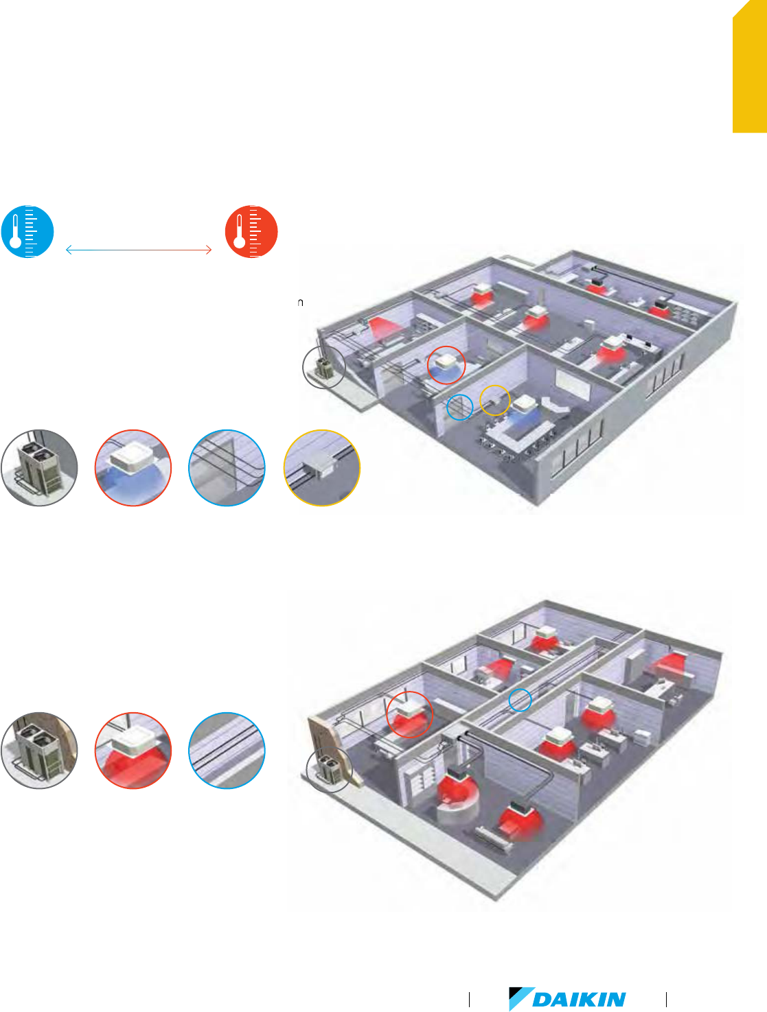
Heat Recovery or Heat Pump?
Simultaneous heating AND cooling from one system
Efficient heating production by transferring
heat from areas requiring cooling
Maximum individual comfort in all areas
Heating operation down to -13°F as standard.
Cooling Heating
Extracted heat from one room/zone
delivers heat to another room/zone
Components:
Outdoor unit Indoor unit
2-pipe
refrigerant piping
Simultaneous heating AND cooling from one system
Outdoor unit Indoor unit 3-pipe
refrigerant piping
Single and multi
Branch Selector boxes:
allows the individual
switching of indoor units
between heating
and cooling
Components:
VRV Heat Recovery
VRV Heat Pump
For either heating OR cooling operation from one system
VRV Product Catalog
7
OVERVIEW
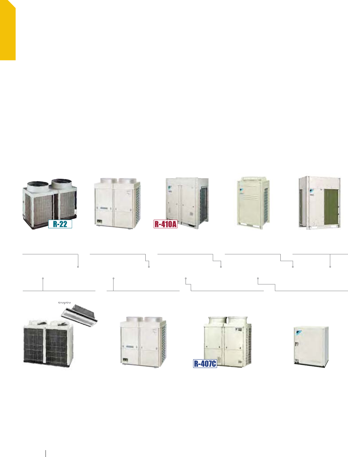
Setting the standards
Over 30 years of VRV history
Daikin invented the first VRV system in 1982 and has continued to
set standards in the industry and heighten market expectations.
Many of the current market expectations are:
Energy efficient inverter compressor
Modular system concept
Heat recovery function
Allow long piping lengths
Heating operation down to -13°F ambient
air temperature as standard
Continuous heat during defrost
Auto charge at start up
VRV was invented in 1982 as a result of the oil crisis around the
world in the 70's. Energy efficiency laws were passed by the
Japanese government. The Japanese government and Daikin
worked closely together — they looked at a chiller system;
pumps, and air handlers as well and how the pump circulates
water and how it uses a lot of power. So, they came up with
a concept to use refrigerant instead of water to circulate as a
heat transfer medium. The first VRV heat recovery system was
launched in 1991 implementing the landmark concept of a heat
pump chiller that circulates refrigerant instead of water.
1982 1987 1990 1991 1998 2003 2005 2007 2014
World’s first R407C VRV
auto addressing
(no rotary or dipswitches)
2nd generation VRV
water cooled technology
VRF is launched globally
World’s first VRV system
is developed
First inverter VRV
Worlds first R410A VRV
heating down to -4°F EEV
in Branch Selector box1st Heat Recovery
is developed
VRV IV LAUNCHED
Continuous heating
during defrost,
auto charge 3280 ft. piping
www.daikincomfort.com8
OVERVIEW
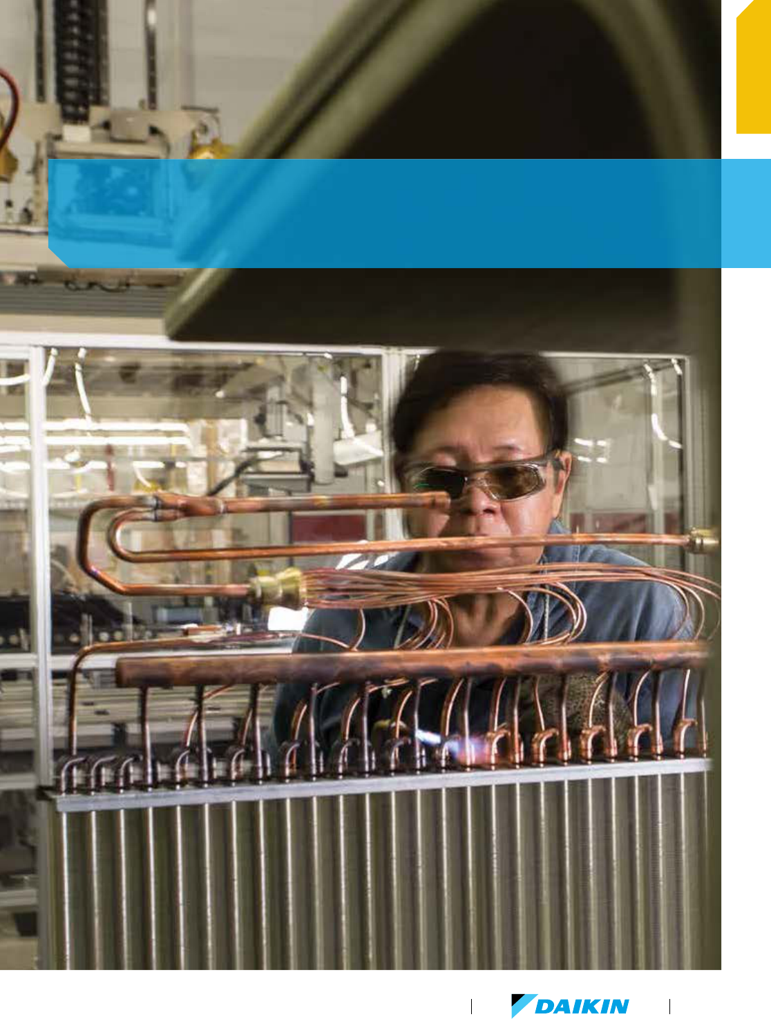
Our quality control is based on the idea that the added value we give to
products is quality, and that this quality is what customers are buying.
And each Daikin employee constantly puts quality ahead of everything else.
VRV Product Catalog
9
OVERVIEW
Optimized life cycle cost
The features of a Daikin VRV IV
system, energy efficient and easy
to design, install, and maintain,
means that it is designed to
reduce the total life cycle cost.
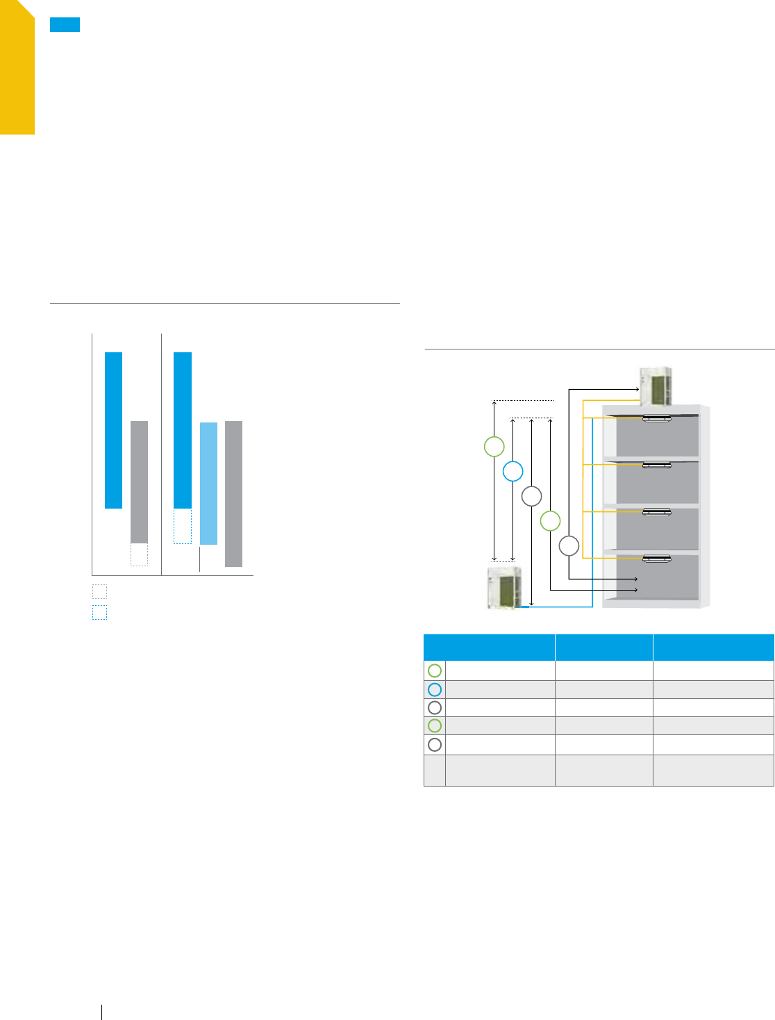
Larger capacity systems saves space
The VRV IV systems reduce installation cost and time as
compared to VRV III. We have increased the largest single module
to 14 tons and the largest double module to 28 tons, while we
made the footprint for the modules smaller. This can mean up
to a 32% reduction in installed space compared to VRV III as it
is possible to achieve greater capacity with the same or smaller
footprint. Again, Daikin has “Set the Standard” by offering a
wide system capacity range and giving customers a reduction
in installation costs coupled with greater application flexibility.
NEW
Daikin VRV IV
Setting the standards, again
Daikin VRV IV sets the standard with the latest technology
and time saving commissioning & servicing
OPTIMIZED
LIFE CYCLE
COST
E
N
E
R
G
Y
E
F
F
I
C
I
E
N
T
E
A
S
Y
T
O
M
A
I
N
T
A
I
N
E
A
S
Y
T
O
I
N
S
T
A
L
L
E
A
S
Y
T
O
D
E
S
I
G
N
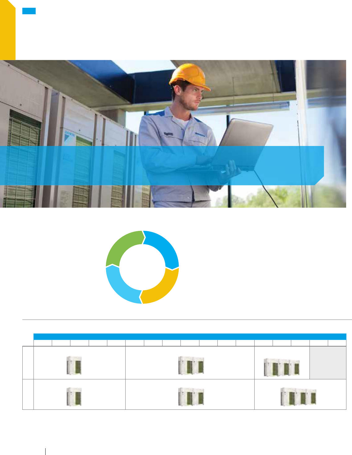
VRV IV Heat Pump and Heat Recovery - Single, dual, and triple modules
CAPACITY - TONS
6810 12 14 16 18 20 22 24 26 28 30 32 34 36 38
Heat Pump
Now up to 14 tons — 17% capacity increase
*
Now up to 28 tons — 40% capacity increase
*
Now up to 34 tons —
13% capacity increase
*
Heat Recovery
Now up to 14 tons — 17% capacity increase
*
Now up to 28 tons — 40% capacity increase
*
Now up to 38 tons — 36% capacity increase
*
* Compared to Daikin VRV III models.
www.daikincomfort.com10
OVERVIEW
Significantly improved energy efficiency
VRV IV combines a number of substantial improvements in
system efficiency and function compared to VRV III.
Larger capacity units now utilize new inverter compressors for
all configurations. This improves overall efficiency and allows the
VRV IV to start with essentially no inrush power. VRV IV uses
a four-sided coil that presents a greater heat exchange surface.
While allowing the same footprint for all unit sizes for ease of
design, we have increased efficiency through improved heat
transfer on all sizes.
The IEER (Integrated Energy Efficiency) for VRV IV Heat Pump
is improved over VRV III by an average of 11% with IEER Values
now up to 28. For VRV IV Heat Recovery the improvements are
even greater with 20% average improvements and IEER Values
now up to 29.3.
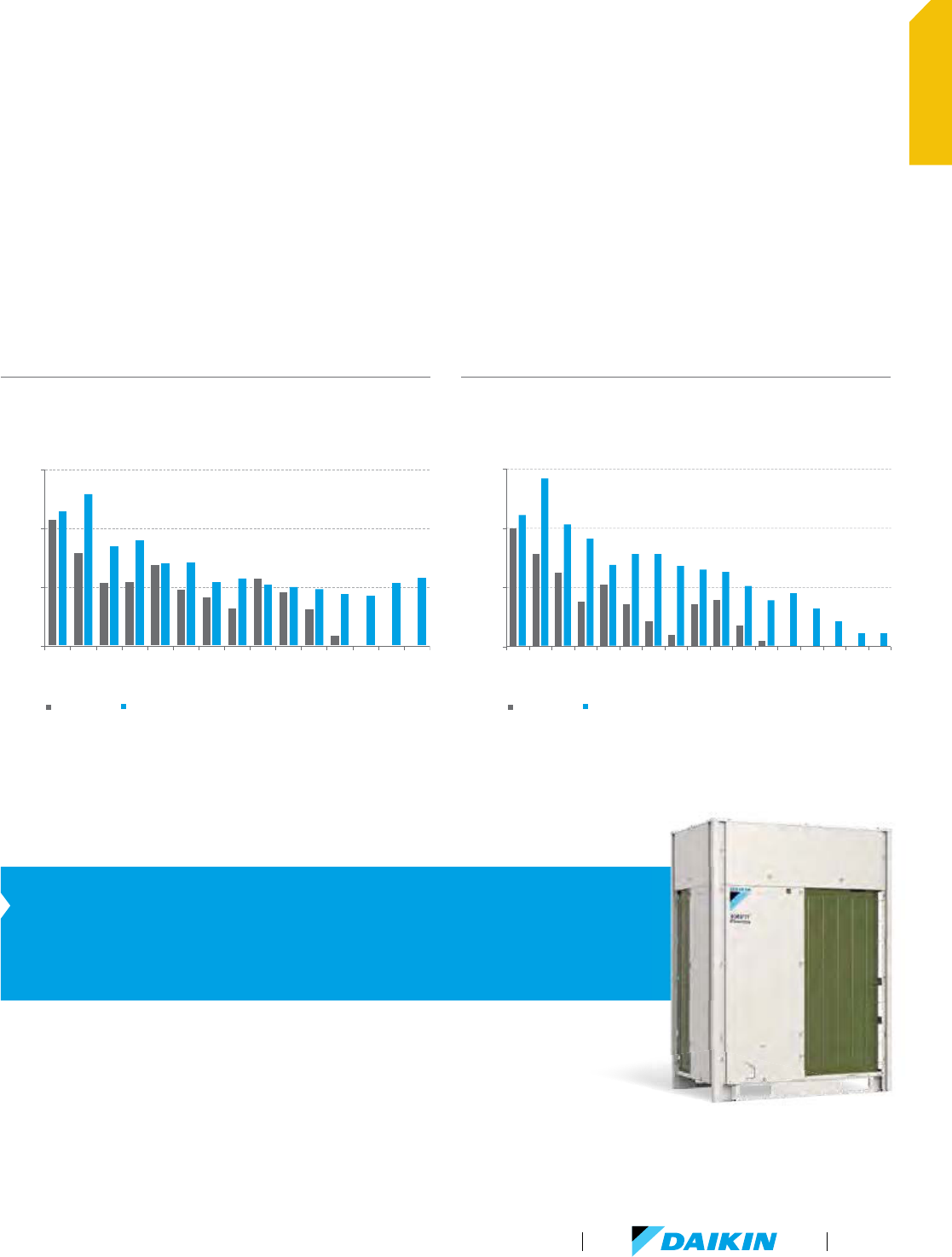
VRV IV Heat Pump
IEER improved by up to 28% over VRV III — average of 11% over full range
VRV IV Heat Recovery
IEER improved by up to 36% over VRV III — average of 20% over full range
SCHE (Simultaneous Cooling and Heating Efficiency)
improved for VRV IV HR by up to 43% over VRV III —
Average improvement of 33% over full product size range.
VRV IV Heat Pump - Significantly Improved Efficiency
IEER improved by up to 28% over VRV III - Average of 11% over full range
VRV IV Heat Recovery - Significantly Improved Efficiency
IEER improved by up to 36% over VRV III - Average of 20% over full range
15
20
25
30
6810 12 14 16 18 20 22 24 26 28 30 32 34
IEER
Non - Ducted IEER
Non - Ducted IEER
VRV III HP
VRV IV HP
VRV III HP
VRV IV HP
Nominal Capacity (Ton)
15
20
25
30
6810 12 14 16 18 20 22 24 26 28 30 32 34 36 38
IEER
Nominal Capacity (Ton)
VRV Product Catalog
11
OVERVIEW
The Inventor of VRV is setting the standard again by introducing VRT
(Variable Refrigerant Temperature) – State-of-the-art energy-saving technology for VRV
Customize your VRV for optimal annual efficiency
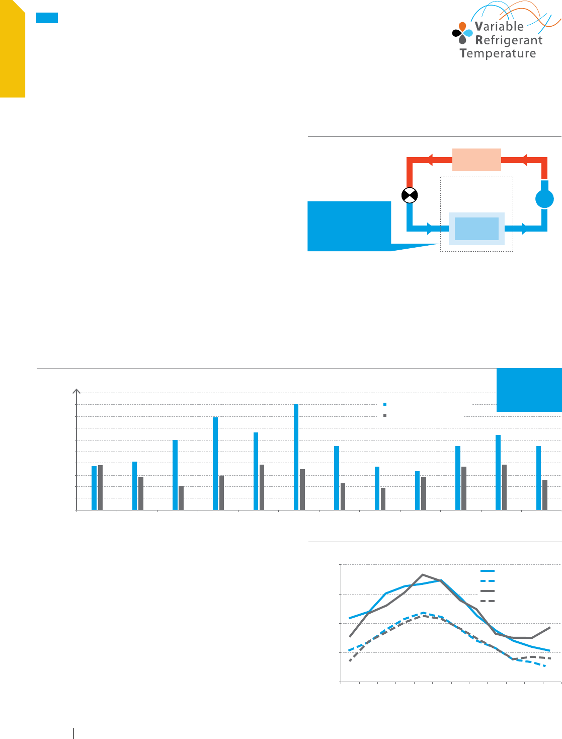
The new VRV IV system now features VRT technology. VRT
automatically adjusts refrigerant temperature to individual
building and climate requirement, thus further improving annual
energy efficiency and maintaining comfort. With this excellent
technology, utility costs are reduced.
How is energy reduced?
A standard VRF system, and previous VRV systems, utilize a
capacity based control logic where the system will adjust to
meet the capacity requirements of the space. With VRT Daikin
have optimized to focus not only on capacity but efficiency
and comfort.
According to changes in the room heat load and the ambient air
temperature, the evaporating temp. (in cooling) and condensing
temperature (in heating) are automatically adjusted to minimize
the difference with the condensing temperature and the
evaporation temperature, respectively.
This makes the compressors work less and also enables the
system to always maintain the ideal compressor speed so that
the Daikin VRV system can deliver the optimum efficiency.
Compressor
Evaporator
Condenser
Evaporating
temperature raised –
Compressor
workload reduced
Indoor unit
heat exchanger
Refrigerant cycle (during cooling)
0
500
1000
1500
2000
2500
3000
3500
4000
4500
5000
Mar Apr May Jun Jul Aug Sep Oct Nov Dec Jan Feb
Monthly energy usage (kWh)
Year 1- VRV III without VRT
Year 2- VRV IV with VRT
Case study – Measured monthly energy usage for a VRV system without VRT and with VRT, installed in a European retail shop
Refrigerant cycle during cooling
NEW
Daikin VRV IV
Setting the standards, again (continued)
86
68
50
32
14
Mar Apr May Jun Jul Aug Sep Oct Nov Dec Jan Feb
Ambient air temperature (0F)
Year 1 - Average max
Year 1 - Average min
Year 2 - Average max
Year 2 - Average min
Ambient air temperature
Heating degree days and cooling degree days, that are quantitative
indications reflecting demand for energy to heat or cool buildings,
were the same for year 1 and year 2.
The basis to determine whether a specific day is a heating degree
day or a cooling degree day is the daily average ambient air
temperature. Even the average min/max ambient air temperature
were very similar for year 1 and year 2.
VRT
54% annual
energy savings
www.daikincomfort.com12
OVERVIEW
Variable Refrigerant TemperatureFixed Refrigerant Temperature
HIGH SENSIBLE MODE
Fixed target Te
AUTO MODE
Floating target Te depending on heat load
BASIC MODE
Fixed Te - Standard control
Unable to change Te
POWERFUL MODE
Reaction speed Very Fast
QUICK MODE
Reaction speed Fast
MILD MODE
Reaction speed Medium
ECO MODEECO MODE
Energy saving priority
Ca
pacity priority
Floating Te Fixed Te
Ba
sic mode is selected to maintain optimal comfort. VRT is selected to save energy and prevent excessive cooling.
Sele
cting VRT enables operation to be optimised for either energy efficiency or rapid cooling.
Can boost capacity above 100%
if needed.
The refrigerant temperature can go
lower in cooling than the set minimum.
Gives priority to very fast
reaction speed.
The refrigerant temperature goes down
fast to keep the room setpoint stable.
Gives priority to fast reaction speed.
The refrigerant temperature goes
down fast to keep the room
setpoint stable.
Gives priority to efficiency.
The refrigerant temperature goes
down gradually giving priority to the
efficiency of the system instead of the
reaction speed.
Fine control to match user preference available through mode selection
*
In markets where cooling is dominant. VRT functionality
for heating operation improves the efficiency as well.
Up to 28% improved seasonal
cooling efficiency vs. VRV III.
*
VRV Product Catalog
13
OVERVIEW
Extended Operation Range —
Heating operation down
to -13°F outdoor temperature
Daikin VRV IV heat recovery systems can provide heating inside
the building even when the outside air temperature is as low as
-13°F as standard. Heat pump systems provide heating down
to -4°F. This enables enhanced application flexibility and use of
the system in colder regions.
Piping flexibility —
More options for installation location
The VRV IV provides very flexible piping possibilities. These
generous allowances outlined in the figure facilitate an extensive
variety of system designs.
100 ft. maximum vertical difference between indoor units
provides greater flexibility for riser type piping layouts.
Allows for up to 12 floors to be served
from a single VRV System
Ideal for mid- to high-rise chiller or WSHP replacement projects
Refrigerant Piping Limitations
MAXIMUM PIPING
DISTANCE
VRV-IV HEAT PUMP VRV-IV HEAT RECOVERY
A
Vertical drop, ft. 164 (295)
*
164 (295)
*
B
Between IDU, ft. 100 100
C
Vertical rise, ft. 131 (295)
*
131 (195)
*
D
From 1st joint, ft. 131 (295)
**
131 (295)
**
E
Linear length, ft. 541 541
Maximum total one-way
piping length, ft.
3282 3282
*
Setting adjustment on condensing unit required.
**
IDU distance differentials need to be met
122˚F
77˚F
23˚F
VIA technical cooling function
-4˚F
-13˚F
Ambient
Heat Pump
Cooling
Cooling
Heating
Heating
Simultaneous
VIA extended capacity tables
Heat Recovery
Temperature Limits
NEW
Daikin VRV IV
Setting the standards, again (continued)
B
A
C
D
E
www.daikincomfort.com14
OVERVIEW
Improved connection ratio flexibility
To properly match outdoor units with indoor units, VRV system
designers calculate the connection ratio.
If a system has more combined indoor unit capacity index than
combined outdoor unit capacity index, the result is a combination
ratio that is greater than 100%. If the outdoor unit combined
capacity index is higher than the index for indoor units, the
combination ratio is less than 100%.
Most VRF systems do not allow the combination ratio to be more
than 130%. However, due to the advanced design of the Daikin
VRV IV system, the connection ratio is in most cases allowed
to be up to 200%.
This generous connection ratio range enables increased flexibility
when a VRV system is designed.
Connection ratio 50%–200%
Connection ratio =
Total capacity index
of the indoor units
Total capacity index
of the outdoor units
Conditions of VRV indoor unit connection capacity
APPLICABLE VRV
INDOOR UNITS
FXDQ, FXMQ-P,
FXAQ MODELS
OTHER VRV INDOOR
UNIT MODELS
*
Single outdoor units
200%
200%
Double outdoor units 160%
Triple outdoor units 130%
*
For FXFQ07, FXFQ09 and FXTQ models, maximum connection ratio is 130% for the entire range of outdoor units.
VRV Product Catalog
15
OVERVIEW
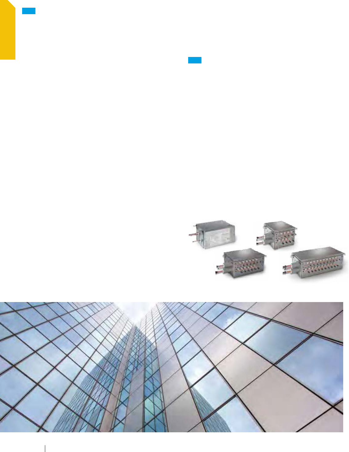
NEW
Branch selector boxes
for ultimate flexibility
Providing flexibility and minimizing mechanical and electrical
installation costs, Daikin's branch selector boxes are ideal for
spaces that require individual heating and cooling control.
Extended range of product offerings with 1, 4, 6, 8, 10 and
12 port options
No drain or condensate consideration required
Unlimited number of unused ports per box or system
Reduced electrical and mechanical installation costs
Ultimate flexibility — choose multi-port or single-port styles
to customize your design
Up to 72% reduction in footprint, as compared to previous
generation models
Up to 17% lower sound levels compared
to current VRV III models
Up to 65% reduction in weight, as compared to previous
generation models
Advantages of 3-pipe technology
Daikin 3-pipe technology used in heat recovery systems has
dedicated refrigerant pipes for suction gas, liquid and discharge
gas. The dedicated refrigerant pipes provide smooth and efficient
refrigerant flow during all main modes of operation and aid with
the heating performance of the system
In a 2-pipe heat recovery system, where the gas and liquid travel
as a mixture in the refrigerant pipes, the condensing temperature
needs to be higher in order to separate the mixed gas and
refrigerant. The higher condensing temperature that is needed
means that the compressor has to work harder. In addition, the
disturbed refrigerant flow in large pipes on 2-pipe system results
in extra pressure drop which can negatively impact the system
capacity and efficiency.
NEW
Daikin VRV IV
Setting the standards, again (continued)
www.daikincomfort.com16
OVERVIEW
20% higher blade
50% thinner blade
50% more
compression volume
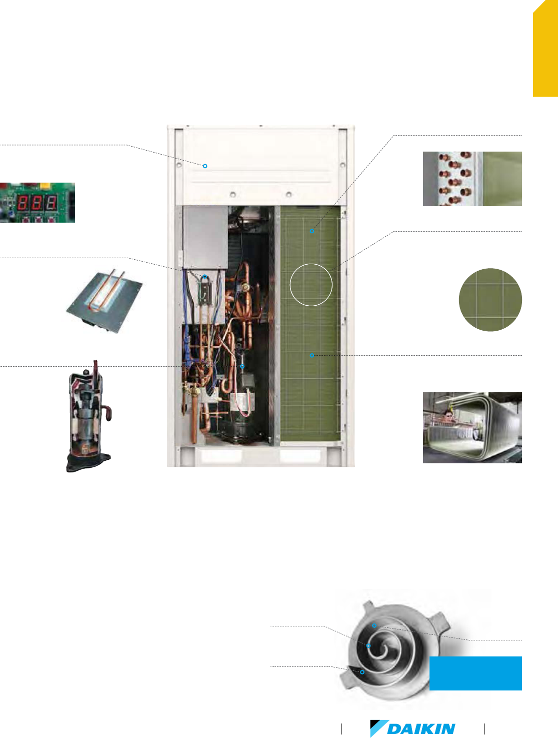
2.4 TIMES STRONGER
than previous generation
Inverter board cooled
by refrigerant circuit
Minimum influence on electronics
from ambient temperature.
Section of the coil in the
unit is permanently
set as condenser for
cooling of the
inverter board.
New compressor
increases performance
New 6-pole motor
50% stronger
magnetic force than
4-pole motor
2% higher efficiency
at part load than
4-pole motor
7mm Coil — 3 Row
Improved heat exchanger efficiency
4-sided heat exchanger coil
50% more heat exchanger surface than
VRV III — more capacity and higher
efficiencies from the same footprint
New efficient technology from Daikin
Simplified commissioning
and after-sales service
VRV IV system utilises a 7-segment display
for system operation information, enabling
the operational state to be visually displayed
whilst facilitating
simplified
commissioning and
after-sales service.
Corrosion protected coil
The VRV IV comes as standard with a
corrosion protected coil — 1000 hr of salt
fog testing according to ASTM B117.
Inverter board cooled by refrigerant circuit
An inverter Printed Circuit Board (PCB) cooled with the liquid
refrigerant circuit increases allows more airflow to the VRV
IV cooling coil to increase efficiency and also minimizes any
influence on the inverter board from ambient temperatures.
4-Sided heat exchanger coil for efficiency
A 4-sided condenser with up to 3 coil rows utilizing 7 mm tubing
means even though the VRV IV has similar footprint as the
VRV III, the efficiency is increased while the refrigerant charge
is less in most models.
Advanced compressor technology
Daikin J Type Inverter Scroll Compressor has a 50% thinner
and a 20% higher scroll blade than the previous generation,
which is realized by adapting a newly developed material. This
technology increases compression volume by 50%. With the
new J Type Compressor and utilizing all inverter compressors,
the Maximum Overload Protection (MOP) is reduced by up to
29% compared to VRV III.
VRV Product Catalog
17
OVERVIEW
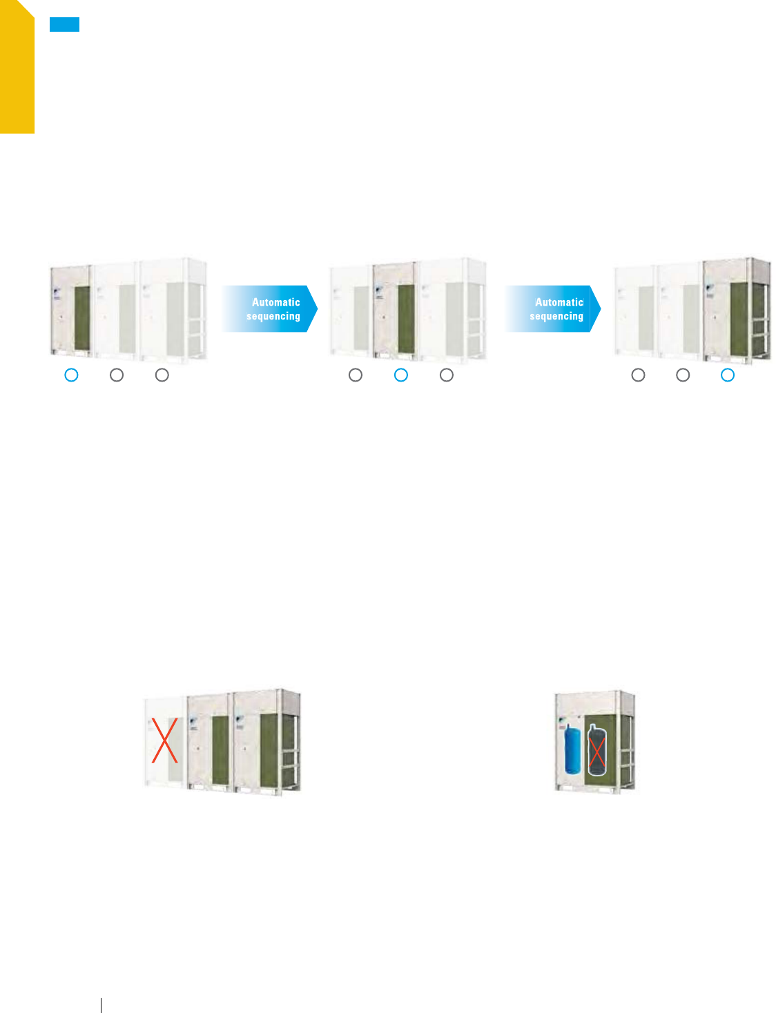
Outdoor unit sequencing technology
Automatic sequencing operation
During start-up, Daikin VRV IV unit sequencing operation will be automatically enabled to ensure balanced operation of each outdoor
unit to improve longevity of equipment and stable operation.
NEW
Daikin VRV IV
Setting the standards, again (continued)
Automatic
sequencing
1 2 3
Stage 1
Priority
1 23
Stage 2
Priority
12 3
Stage 3
Priority
Double backup operation functions responding
resiliently to various unexpected situations
Double backup operation functions
Daikin VRV IV system boasts double backup operation functions, which can secure the use of air conditioners in this area to the greatest
extent by emergently enabling double backup operation functions even if failure occurs in a set of air conditioning equipment. In the
event of a failure, emergency operation can be conveniently enabled to allow the remaining system to operate in a limited fashion.
Unit backup operation function
If malfunction occurs in an outdoor unit...
Emergency operation can be conveniently set and enabled by
the remote controller for indoor unit (for systems composed of
two or more outdoor units).
Compressor backup operation function
If malfunction occurs in a compressor...
Emergency operation can be easily set and enabled
by the outdoor unit.
Automatic
sequencing
www.daikincomfort.com18
OVERVIEW

With the VRV IV heat pump and heat recovery systems, the Daikin
brand is one of the most extensive lines of heating and cooling systems
in North America.
VRV Product Catalog
19
OVERVIEW
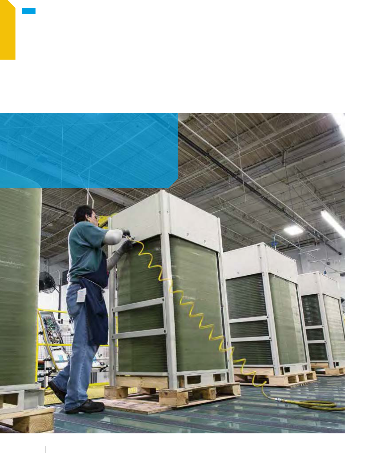
VRV IV outdoor units assembled in the U.S.A.
The VRV IV is the first variable refrigerant flow (VRF) system to be
assembled in North America. With a state of the art production
line, local / in house preparation, tooling, processing and
construction of heat exchangers, refrigerant cycle assemblies,
sheet metal parts, electrical box, etc., we can react quickly to
changes in the market-place and truly optimize the product for
the North American market.
Extensive local inventory
and short lead times.
Typically, 98% of replacement
parts can be shipped in
approximately 48 hours.
NEW
Daikin VRV IV
Setting the standards, again (continued)
www.daikincomfort.com20
OVERVIEW
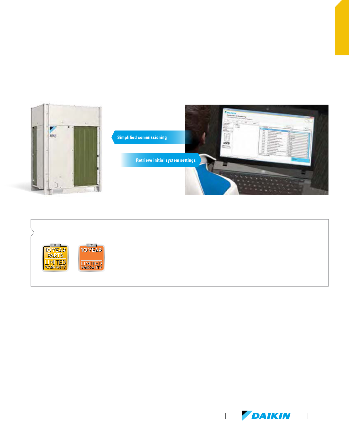
VRV system configuration and commissioning
The VRV configurator is an advanced software solution that
allows for easy system configuration and commissioning.
Less time is required on the roof configuring the outdoor unit.
Multiple systems at different sites can be managed in exactly
the same way, thus offering simplified commissioning for
key accounts.
Initial settings on the outdoor unit can be easily retrieved.
Outstanding 10 Year Parts and Compressor Warranty
*
replacement
compressor
replacement
compressor
Outstanding warranty
*
with 10 Year
Replacement Compressor Limited Warranty
and 10 Year Parts Limited Warranty as
standard ensures our confidence in our
new VRV IV.
*
Complete warranty details available
from your local Daikin manufacturer’s
representative or distributor or online at
www.daikincomfort.com.
Retrieve initial system settings
Retrieve initial system settings
Simplified commissioning
VRV Product Catalog
21
OVERVIEW

See how you can profit from
Daikin’s flexible and efficient
product range.
NEW
Daikin VRV IV
What does a VRV installation mean to you?
Consulting engineers
Daikin's VRV IV technology maximizes flexibility and leads the
way in customization to match individual building requirements
in comfort and energy — all designed to reduce the total life
cycle costs.
Maximum flexibility to meet customer requirements
Advanced software tools assist with system design
Building owners
VRV IV is the ultimate in customized comfort and intelligent
control tailored to your individual needs and used to maximize
energy efficiency.
Optimized life cycle cost
No more cold droughts with variable refrigerant temperature
Single point of contact for the design of your climate system
Integrated system, combining air conditioning, heating,
ventilation, etc., enables optimized system function
Multiple systems can be managed in exactly
the same way for key accounts
Dedicated after-sales service to ensure fast on-site support
www.daikincomfort.com
22
OVERVIEW

Installers
Daikin VRV IV sets the standard with state-of-the-art technology
and time-saving commissioning and servicing.
Simplified and time-saving commissioning
with VRV configurator
Unique range of single and multi Branch Selector boxes
reduce installation time compared to previous generation
Wide range of outdoor units (up to
38 Tons for heat recovery)
One supplier equals one point of contact
Maximum flexibility to meet customer requirements
Customized training to maximize expertise
Architects
Indoor units with a sleek and sophisticated design
Space efficient outdoor units
Low sound levels for both indoor and outdoor units
Wide range of indoor units to allow
installation in most environments
VRV Product Catalog
23
OVERVIEW
NEW
Daikin VRV IV
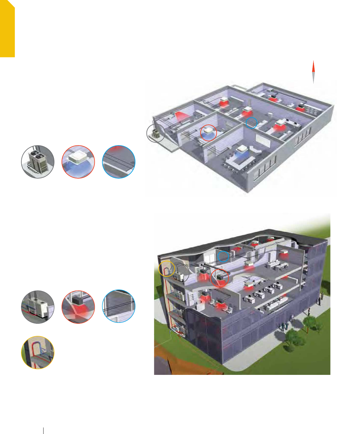
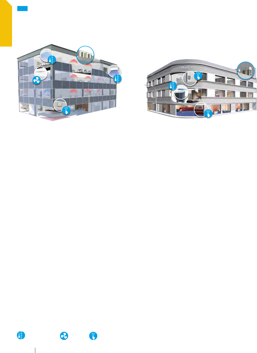
Vertical market applications
VRV for offices and banks
Our office solution offers:
Increased occupant productivity with individual zone control,
low sound levels & tight temperature control
Optimized energy efficiency
Simple maintenance — low operational cost
Modular system allowing cost effective out-of-hours operation
Integrated ventilation solutions allowing high indoor air quality
Complete Daikin Building Management System for office
building management with Intelligent Touch Manager
Remote monitoring with email alerts
Self-cleaning filters yielding operational and maintenance
cost savings
Intelligent sensors on round flow cassette maximizing
efficiency by innovative occupancy sensing features
VRV for hotels
Our hotel solution offers:
Energy efficient systems capable of simultaneous heating
and cooling.
Ultra-quiet guest room solutions discrete and simple to control.
Flexible installation options lowering installation complexity,
costs and space requirements than most traditional
HVAC systems
Inverter technology creating the perfect guest room
environment by regulating temperature swings and humidity
Centralized control with the iTouch Manager improving owner
/ management operational capabilities
Seamless integration & compatibility with industry
acclaimed INNCOM systems delivering combined benefits
in guest operations and experience for both guests and
management team
Heating and cooling
Ventilation
Intelligent control system
www.daikincomfort.com24
OVERVIEW
*
Complete warranty details available from your local Daikin
manufacturer’s representative or distributor or online at
www.daikincomfort.com.
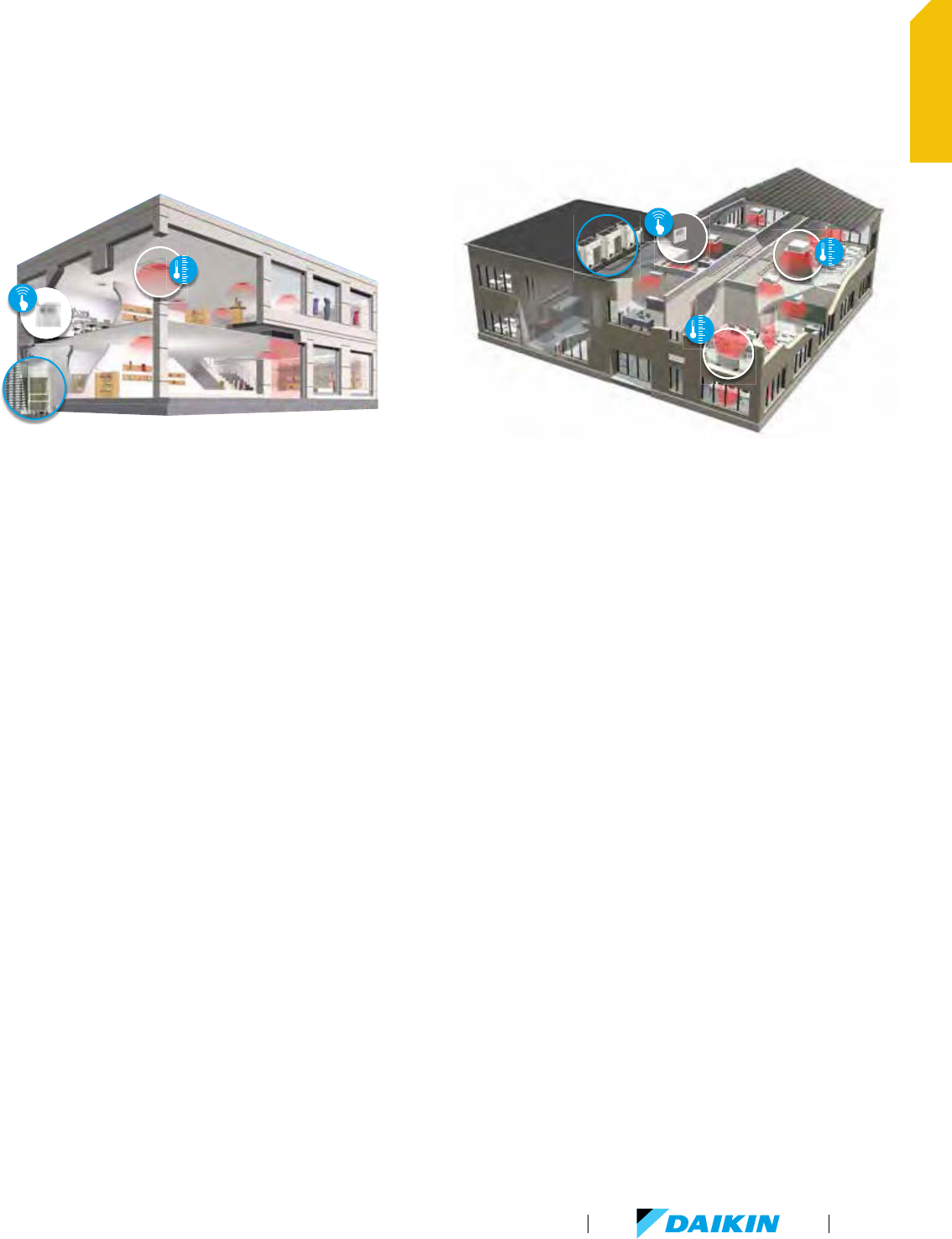
VRV for retail and restaurants
Our retail solutions offer:
Scalable project opportunities with modular design
Individual zone control for advanced zoning capabilities
Enhanced efficiency in retail chain operations and energy usage
from Daikin's complete Building Management System with
Intelligent Touch Manager
Centralized building control & autonomy from VRV remote
commissioning and management capability
10 years limited parts and compressor warranty*
VRV for schools
Our school solution offers:
Flexible, scalable total HVAC solution for school classrooms,
common areas and administrative offices
Over 12,000 Daikin VRV systems in schools in North America
Quiet operating sound levels as low as 28 dB(A)
Minimal occupant air temperature variations
Advanced zoning capabilities with user-friendly and
intuitive controls
Modular in design accommodating unique
school and classroom spaces
Combined benefits of energy and operations efficiency
for both school administrators & maintenance staff
10 year limited parts and compressor warranty*
VRV Product Catalog
25
OVERVIEW

www.daikincomfort.com26

VRV Product Catalog
27
Product Portfolio
Product portfolio
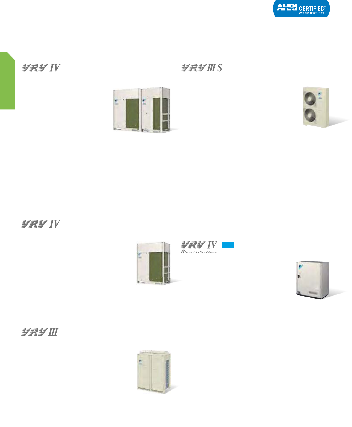
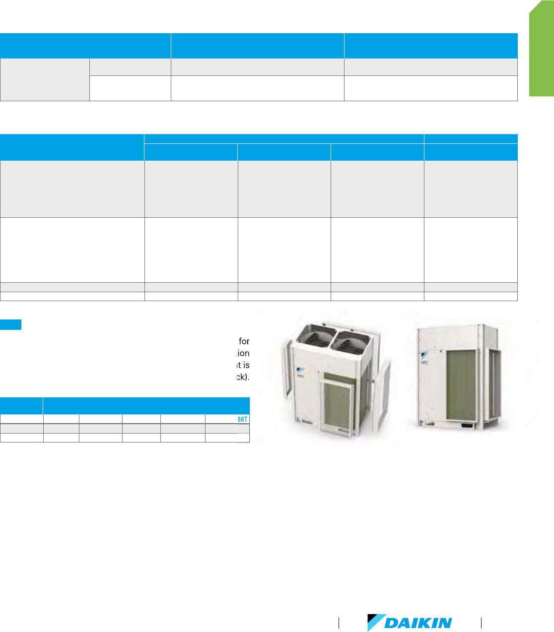
Outdoor units
Heat Recovery
Fully integrated solution with heat
recovery offers high efficiencies
with IEER values up to 29.3
Total comfort solution for heating,
cooling, ventilation, and controls
Outstanding warranty
*
with 10 year
compressor and parts limited
warranty as standard
Perfect personal comfort for guests / tenants via simultaneous
cooling and heating
Incorporates VRV IV standards and technologies such as
variable refrigerant temperature and all inverter compressors
Unique range of single and multi-port branch selector boxes
Heating function down to -13°F ambient air temperature
Daikin VRV IV is the first variable refrigerant flow (VRF) system
to be assembled in North America.
Heat Pump
Total comfort solution for heating, cooling,
ventilation and controls
Energy efficiency values (IEER) up to 28.0
Incorporates VRV IV standards and
technologies such as variable refrigerant
temperature and all inverter compressors
Best-In-class warranty
*
with 10 year
compressor and parts limited warranty as standard
Daikin VRV IV is the first variable refrigerant flow (VRF) system
to be assembled in North America.
Heat Recovery
Advanced continuous heating during defrost
cycle and oil return for single module systems
Variable Refrigerant Temperature
(VRT) control
Extended operating range with heating
function down to -4°F ambient air temperature
Air-Cooled
VRV III-S systems are equipped with built-in
intelligence which provide independent zoning
control with maximum flexibility and energy
savings. With the ability to connect up to eight
indoor units to one outdoor unit, the space-saving
VRV III-S system is ideal for most light commercial
and residential applications.
Single phase technology
Smaller capacity for precise temperature control
Space-saving design and flexible indoor unit
options offer quick and easy installation
Superior energy efficiency, especially
under part load conditions
Soft sound levels for comfort
Single-supplier reliability
Straightforward maintenance and service
with self-diagnostic functions
Condensing unit
Water Cooled
Enables geothermal energy as an energy source
Can be applied to both geothermal and boiler,
cooling tower applications
Geothermal mode eliminates need for an
external heating or cooling source
Compact and lightweight design can be stacked for maximum
space saving
Can be applied to both geothermal and boiler/tower applications
as standard with condenser water inlet temperature as low as
14°F in heating and 27°F in cooling is possible
*
Complete warranty details available from your local Daikin
manufacturer’s representative or distributor or online
at www.daikincomfort.com.
NEW
28
PRODUCT PORTFOLIO
www.daikincomfort.com
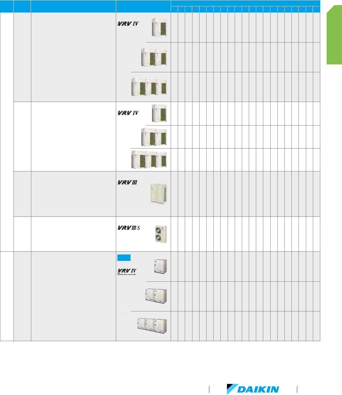
TYPE
MODEL
FEATURES PRODUCT NAME
CAPACITY (TONS)
3467810 12 14 16 18
20
21
22
24
26
28
30
32
34
36
38
Air cooled
VRV IV Heat Recovery
Best efficiency & comfort solution
Fully integrated solution with heat
recovery for high efficiencies with
IEER of up to 29.3
Covers all thermal needs of a building
via a single point of contact for accurate
temperature control
The perfect personal comfort for guests/
tenants via simultaneous cooling and heating
Incorporates VRV IV standards & technologies
such as Variable Refrigerant temperature and
all inverter compressors
Widest range of Branch Selector boxes
on the market
REYQ-T
VRV IV Heat Pump
Daikin’s solution for comfort
& low energy consumption
Covers all thermal needs of a building
via a single point of contact for accurate
temperature control
RXYQ-T
VRV III PC Heat Recovery
Advanced continuous heating during defrost
cycle and oil return for single module systems
Variable Refrigerant Temperature
(VRT) control
Extended operating range with heating
function down to -4°F ambient air
temperature
REYQ-PC
*
VRV III-S
Heat Pump
Single phase technology
Space saving solution without
compromising on efficiency
For residential and light
commercial applications
RXYMQ-PV
Water cooled
VRV IV W-Series Heat Recovery / Heat Pump
Ideal for high rise buildings, using water
as heat source
Enables use of geothermal energy as a
renewable energy source
No need for an external heating or cooling
source when used in geothermal mode
Covers all thermal needs of a building
via a single point of contact for accurate
temperature control
Compact & lightweight design can be stacked
for maximum space saving
Incorporates VRV IV standards & technologies
such as Variable Refrigerant temperature and
all inverter compressors.
NEW
RWEYQ-PC
* 208-230V/3Ph/60Hz only
VRV Product Catalog
29
PRODUCT PORTFOLIO
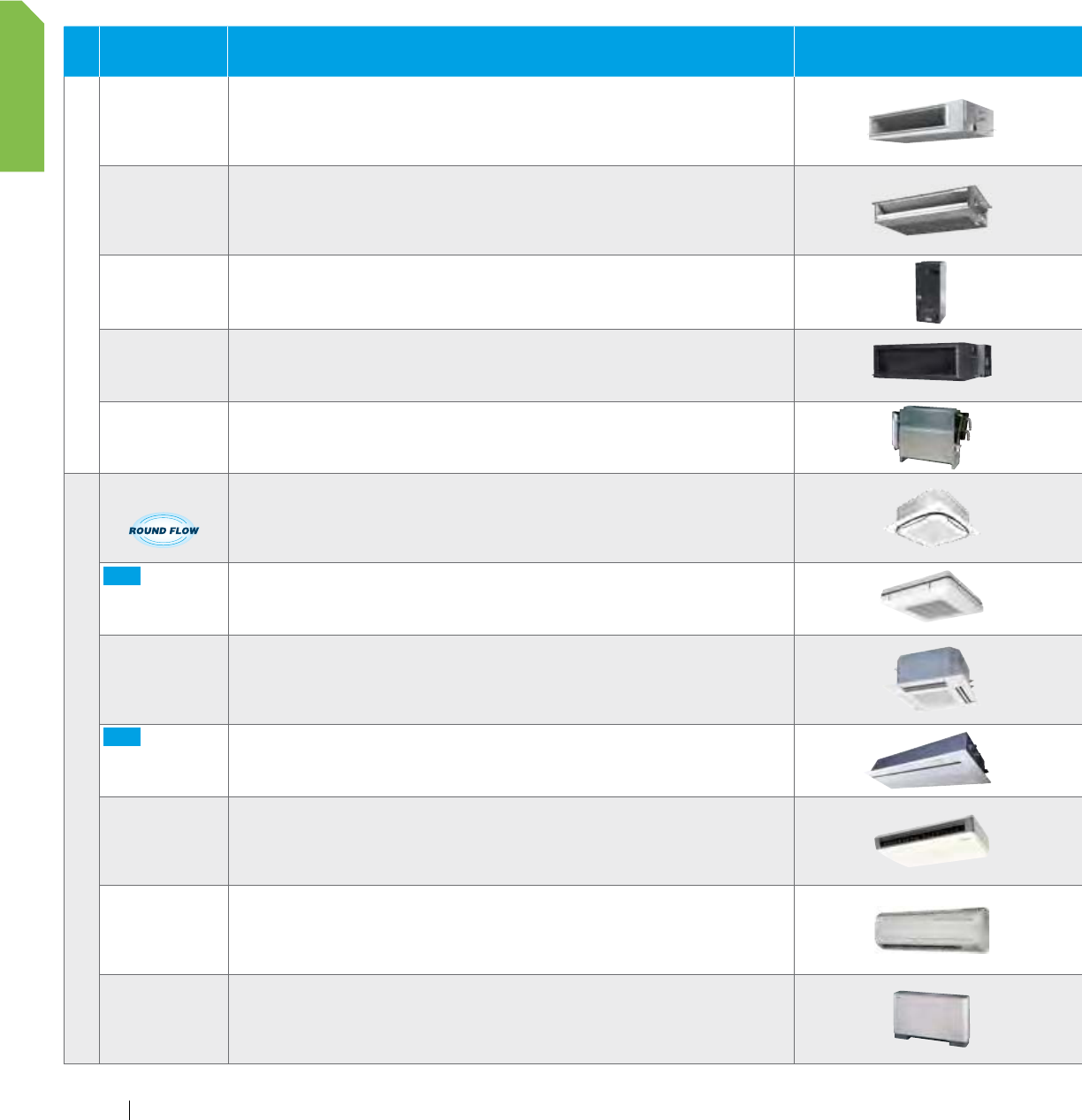
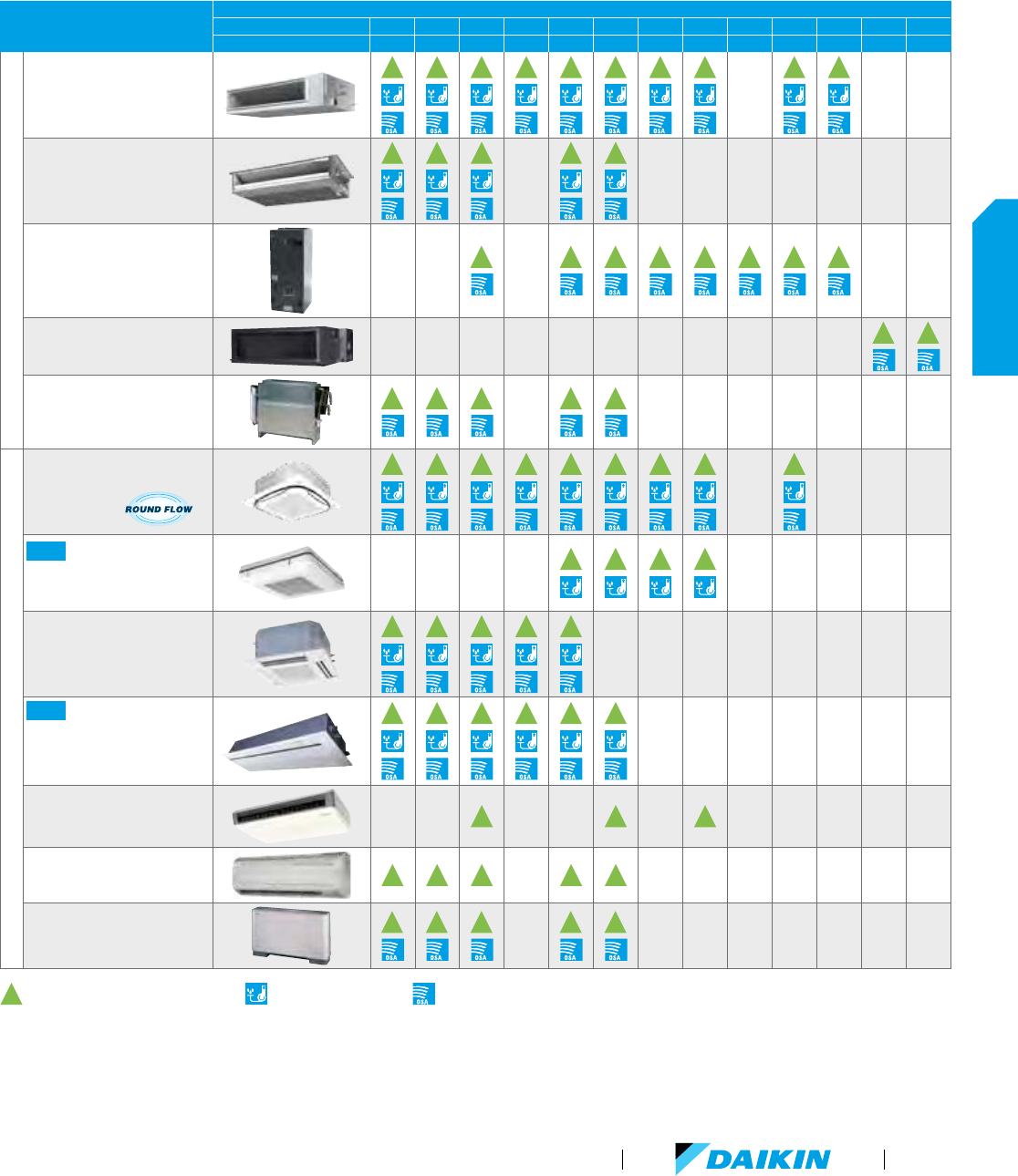
Indoor Units
TYPE
MODEL FEATURES PRODUCT NAME
CAPACITY
MBH 7.5 9.5 12 15 18 24 30 36 42 48 54 72 96
TON 0.6 0.75 1 1.25 1.5 2 2.5 3 3.5 4 4.5 68
Ducted
DC-Ducted Concealed
Ceiling Unit
Energy efficient due to the DC fan motor
Ideal to use together with the optional Daikin Zoning Kit, DZK
Enhanced indoor air quality and LEED ready with MERV 13 filter options
Flexible ductwork design with ESP capabilities up to 0.8" W.G.
Installation flexibility with a low profile, compact design at less than 12" in height
FXMQ-PBVJU
Slim-Duct, Built-In
Concealed Ceiling Unit
Slim height, at only 7-7/8"
Washable filter included
Low sound level
Factory shipped for rear air inlet —field convertible to bottom air inlet
Condensate pump with vertical lift of up to 21-5/8" included as standard
FXDQ-MVJU
Vertical Air Handling Unit
Ideal replacement for fan coils, geothermal heat pumps or traditional splits systems
Upflow and horizontal right installation is permitted
ECM fan motor provides energy efficiency
Wide line up of electric heat (field installed) options from 3kW to 20kW
FXTQ-PAVJU
Concealed Ceiling Unit
(Medium Static)
Design flexibility with a capacity range up to 96 MBH
Improved ductwork and filtration flexibility with high CFM and ESP capabilities
Low profile design of less than 19" high to reduce required installation space
Ideal for Hotels, Schools, Retail
FXMQ-MVJU
Concealed Floor-
Standing Unit
Ideal for installation beneath a window
Requires minimal installation space
Fitted with a washable long-life filter
Space-saving unit can be freestanding or wall-mounted
FXNQ-MVJU9
Duct-Free
Round Flow
Sensing Cassette
True 360° Airflow and three room sensors enables optimized occupant comfort
Energy efficient with DC fan motor and auto-logic that adjusts fan speed
Optional self-cleaning filter panel to further increase efficiency and reduce maintenance
Increased indoor air quality with high efficiency filter options and ventilation connection kit
Very flexible with 18 different possible airflow patterns
FXFQ-TVJU
NEW
4-Way Ceiling-Suspended
Cassette
Very low unit height of under 8"
Optional Sensor Kit enables input from three room sensors
Stylish unit blends easily with any interior
Individual air louver control
FXUQ-PVJU
2' x 2' 4-Way
Ceiling-Mounted Cassette
Fits in a standard 2' x 2' ceiling grid.
Sound pressure levels are as low as 29 dB(A)
Space-saving depth of units requires only 11.6" of ceiling space
Easy-to-clean grille, washable long-life filter
Simple installation with an easy-to-fit decoration panel
FXZQ-MVJU9
NEW
Ceiling-Mounted Cassette
(Single flow)
Only 7-⅞" in height and a width of 18-½" making it possible to use this style of indoor unit in the tightest of spaces
The unit is equipped with both horizontal and vertical louvers to optimize the airflow and throw to suite your room design
The indoor unit can be set to 5 predetermined fan speeds which allows for optimum and comfortable airflow
Factory installed condensate pump with a lift capacity of up to 33-7/16" (measured from the bottom of the unit)
FXEQ-PVJU
Ceiling-Suspended Unit
One of our slimmest indoor units, less than 8"
Wide air discharge outlet distributes a comfortable airflow throughout the entire space
Innovative stream fan technology keeps sound pressure levels low
Smooth flat louver design makes cleaning simple
Long-life filter is standard
FXHQ-MVJU
Wall-Mounted Unit
Auto-swing mechanism ensures efficient air distribution via louvers
Wide air discharge outlet distributes a comfortable airflow throughout the entire space
Horizontal louvers and front panel can be easily removed for cleaning
Drain pipe can be easily hidden from sight
Compact and stylish design
FXAQ-PVJU
Floor-Standing Unit
Ideal for installation beneath a window
Unit requires minimal installation space
Fitted with a washable long-life filter
Remote-control options available
Space-saving unit can be freestanding or wall-mounted
FXLQ-MVJU9
Product portfolio (continued)
30
PRODUCT PORTFOLIO
www.daikincomfort.com
Indoor Units
TYPE
MODEL FEATURES PRODUCT NAME
CAPACITY
MBH 7.5 9.5 12 15 18 24 30 36 42 48 54 72 96
TON 0.6 0.75 1 1.25 1.5 2 2.5 3 3.5 4 4.5 68
Ducted
DC-Ducted Concealed
Ceiling Unit
Energy efficient due to the DC fan motor
Ideal to use together with the optional Daikin Zoning Kit, DZK
Enhanced indoor air quality and LEED ready with MERV 13 filter options
Flexible ductwork design with ESP capabilities up to 0.8" W.G.
Installation flexibility with a low profile, compact design at less than 12" in height
FXMQ-PBVJU
Slim-Duct, Built-In
Concealed Ceiling Unit
Slim height, at only 7-7/8"
Washable filter included
Low sound level
Factory shipped for rear air inlet —field convertible to bottom air inlet
Condensate pump with vertical lift of up to 21-5/8" included as standard
FXDQ-MVJU
Vertical Air Handling Unit
Ideal replacement for fan coils, geothermal heat pumps or traditional splits systems
Upflow and horizontal right installation is permitted
ECM fan motor provides energy efficiency
Wide line up of electric heat (field installed) options from 3kW to 20kW
FXTQ-PAVJU
Concealed Ceiling Unit
(Medium Static)
Design flexibility with a capacity range up to 96 MBH
Improved ductwork and filtration flexibility with high CFM and ESP capabilities
Low profile design of less than 19" high to reduce required installation space
Ideal for Hotels, Schools, Retail
FXMQ-MVJU
Concealed Floor-
Standing Unit
Ideal for installation beneath a window
Requires minimal installation space
Fitted with a washable long-life filter
Space-saving unit can be freestanding or wall-mounted
FXNQ-MVJU9
Duct-Free
Round Flow
Sensing Cassette
True 360° Airflow and three room sensors enables optimized occupant comfort
Energy efficient with DC fan motor and auto-logic that adjusts fan speed
Optional self-cleaning filter panel to further increase efficiency and reduce maintenance
Increased indoor air quality with high efficiency filter options and ventilation connection kit
Very flexible with 18 different possible airflow patterns
FXFQ-TVJU
NEW
4-Way Ceiling-Suspended
Cassette
Very low unit height of under 8"
Optional Sensor Kit enables input from three room sensors
Stylish unit blends easily with any interior
Individual air louver control
FXUQ-PVJU
2' x 2' 4-Way
Ceiling-Mounted Cassette
Fits in a standard 2' x 2' ceiling grid.
Sound pressure levels are as low as 29 dB(A)
Space-saving depth of units requires only 11.6" of ceiling space
Easy-to-clean grille, washable long-life filter
Simple installation with an easy-to-fit decoration panel
FXZQ-MVJU9
NEW
Ceiling-Mounted Cassette
(Single flow)
Only 7-⅞" in height and a width of 18-½" making it possible to use this style of indoor unit in the tightest of spaces
The unit is equipped with both horizontal and vertical louvers to optimize the airflow and throw to suite your room design
The indoor unit can be set to 5 predetermined fan speeds which allows for optimum and comfortable airflow
Factory installed condensate pump with a lift capacity of up to 33-7/16" (measured from the bottom of the unit)
FXEQ-PVJU
Ceiling-Suspended Unit
One of our slimmest indoor units, less than 8"
Wide air discharge outlet distributes a comfortable airflow throughout the entire space
Innovative stream fan technology keeps sound pressure levels low
Smooth flat louver design makes cleaning simple
Long-life filter is standard
FXHQ-MVJU
Wall-Mounted Unit
Auto-swing mechanism ensures efficient air distribution via louvers
Wide air discharge outlet distributes a comfortable airflow throughout the entire space
Horizontal louvers and front panel can be easily removed for cleaning
Drain pipe can be easily hidden from sight
Compact and stylish design
FXAQ-PVJU
Floor-Standing Unit
Ideal for installation beneath a window
Unit requires minimal installation space
Fitted with a washable long-life filter
Remote-control options available
Space-saving unit can be freestanding or wall-mounted
FXLQ-MVJU9
VRV Product Catalog
31
PRODUCT PORTFOLIO
Accessories
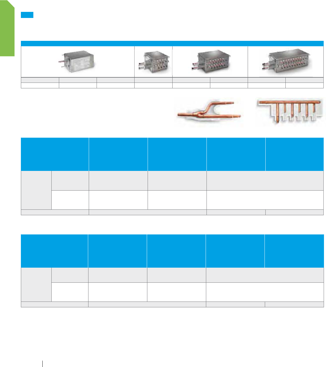
REFNET
REFNET Joints distribute correct flow of refrigerant
in every branch of the piping network.
VRV IV Heat Pump
OPTIONAL ACCESSORIES
RXYQ72T
RXYQ96T
RXYQ120T
RXYQ144T
RXYQ168T
RXYQ192T
RXYQ216T
RXYQ240T
RXYQ264T
RXYQ288T
RXYQ312T
RXYQ336T
RXYQ360T
RXYQ384T
RXYQ408T
Distributed piping
Refnet Header
KHRP26M22H (max. 4 branch)
KHRP26M33H (max. 8 branch)
KHRP26M22H (max. 4 branch)
KHRP26M33H (max. 8 branch)
KHRP26M72H (max. 8 branch)
K
HRP26M22H (max. 4 branch)
KHRP26M33H (max. 8 branch)
KHRP26M72H (max. 8 branch)
KHRP26M73H (max. 8 branch)
R
efnet Joint
KHRP26A22T
KHRP26A33T
KHRP26A22T
KHRP26A33T
KHRP26M72TU
K
HRP26A22T
KHRP26A33T
KHRP26M72TU
KHRP26M73TU
O
utdoor unit multi connection piping kit — BHFP22P100U BHFP22P151U
VRV IV Heat Recovery
OPTIONAL ACCESSORIES
REYQ72T
REYQ96T
REYQ120T
REYQ144T
REYQ168T
REYQ192T
REYQ216T
REYQ240T
REYQ264T
REYQ288T
REYQ312T
REYQ336T
REYQ360T
REYQ384T
REYQ408T
REYQ432T
REYQ456T
Distributed piping
Refnet Header KHRP26M33H (max. 8 branch)
KHRP26M33H (max. 8 branch)
KHRP26M72H (max. 8 branch)
KHRP25M33H9 (max. 8 branch)
KHRP25M72H9 (max. 8 branch)
KHRP25M73H9 (max. 8 branch)
R
efnet Joint
KHRP25A22T9
KHRP25A33T9
KHRP25A22T9
KHRP25A33T9
KHRP25M72TU9
K
HRP25A22T9
KHRP25A33T9
KHRP25M72TU9
KHRP25M73TU9
O
utdoor unit multi connection piping kit — BHFP26P100U BHFP26P151U
NEW
Branch Selector Boxes
Providing flexibility and minimizing mechanical and electrical installation costs, Daikin's branch selector boxes that are used in Heat
Recovery systems, are ideal for spaces that require individual heating and cooling control.
NUMBER OF BRANCHES / MAXIMUM TOTAL CAPACITY INDEX (KBTU/H)
BSQ36TVJ BSQ60TVJ BSQ96TVJ BS4Q54TVJ BS6Q54TVJ BS8Q54TVJ BS10Q54TVJ BS12Q54TVJ
1/36 1/60 1/96 4/144 6/216 8/290 10/290 12/290
Product Portfolio (continued)
REFNET Joint REFNET Header
32
PRODUCT PORTFOLIO
www.daikincomfort.com
NEW
Hail Guard Kit for VRV IV
The optional hail guard kit for VRV IV enables optimal airflow for
efficient heat transfer while providing condenser coil protection
from hail damage in severe climates. Each hail guard kit, that is
field installed, consists of 4 panels (Right, Left, Front and Back).
KIT PART
NUMBER
QUANTITY OF KITS PER VRV IV OU MODEL
R_YQ72T R_YQ96-168T R_YQ192T R_YQ216-336T
R_YQ360-456T
VRV4HGS-K1 1 1 1
VRV4HGL-K1 1 2 3
VRV III PC Heat Recovery
OPTIONAL ACCESSORIES REYQ72PC
REYQ96PC
REYQ120PC
REYQ144PCTJ
Distributed piping
Refnet Header KHRP25M33H9 (max. 8 branch)
KHRP25M33H9 (max. 8 branch)
KHRP25M72H9 (max. 8 branch)
Refnet Joint
KHRP25A22T9
KHRP25A33T9
K
HRP25A22T9
KHRP25A33T9
KHRP25M72TU9
The optional hail guard kit for VRV IV enables optimal airflow for
efficient heat transfer while providing condenser coil protection
from hail damage in severe climates. Each hail guard kit, that is
field installed, consists of 4 panels (Right, Left, Front and Back).
R_YQ360-456T
VRV IV W-Series Heat Pump / Heat Recovery and VRV-III-S
UNIT MODEL NUMBER
VRV IV W-SERIES VRV-III-S
RWEYQ72P
RWEYQ84P
RWEYQ144P
RWEYQ168P
RWEYQ168P
RWEYQ252P
RXYMQ36P
RXYMQ48P
REFNET Header
KHRP25M33H9 (max. 8 branch)
KHRP26M22H9 (max. 4 branch)
KHRP26M33H9 (max. 8 branch)
KHRP25M33H9 (max. 8 branch)
KHRP25M72H9 (max. 8 branch)
KHRP26M22H9 (max. 4 branch)
KHRP26M33H9 (max. 8 branch)
KHRP26M72H9 (max. 8 branch)
KHRP25M33H9 (max. 8 branch)
KHRP25M72H9 (max. 8 branch)
KHRP25M73HU9 (max. 8 branch)
KHRP26M22H9 (max. 4 branch)
KHRP26M33H9 (max. 8 branch)
KHRP26M72H9 (max. 8 branch)
KHRP26M73HU9 (max. 8 branch)
KHRP26M22H9 (max. 4 branches)
KHRP26M33H9 (max. 8 branches)
REFNET Joint
KHRP25M22T9
KHRP25M33T9
KHRP26M22T9
KHRP26M33T9
KHRP25M22T9
KHRP25M33T9
KHRP25M72TU9
KHRP26M22T9
KHRP26M33T9
KHRP26M72TU9
K
HRP25M22T9
KHRP25M33T9
KHRP25M72TU9
KHRP25M73TU9
KHRP26M22T9
KHRP26M33T9
KHRP26M72TU9
KHRP26M73TU9
K
HRP26M22T9
Outdoor Unit Multi Piping Connection Kit (Heat Pump) BHFP22MA56U BHFP22MA84U
Outdoor Unit Multi Piping Connection Kit (Heat Recovery) BHFP26MA56U BHFP26MA84U
VRV Product Catalog
33
PRODUCT PORTFOLIO
Product Portfolio (continued)
Accessories (continued)
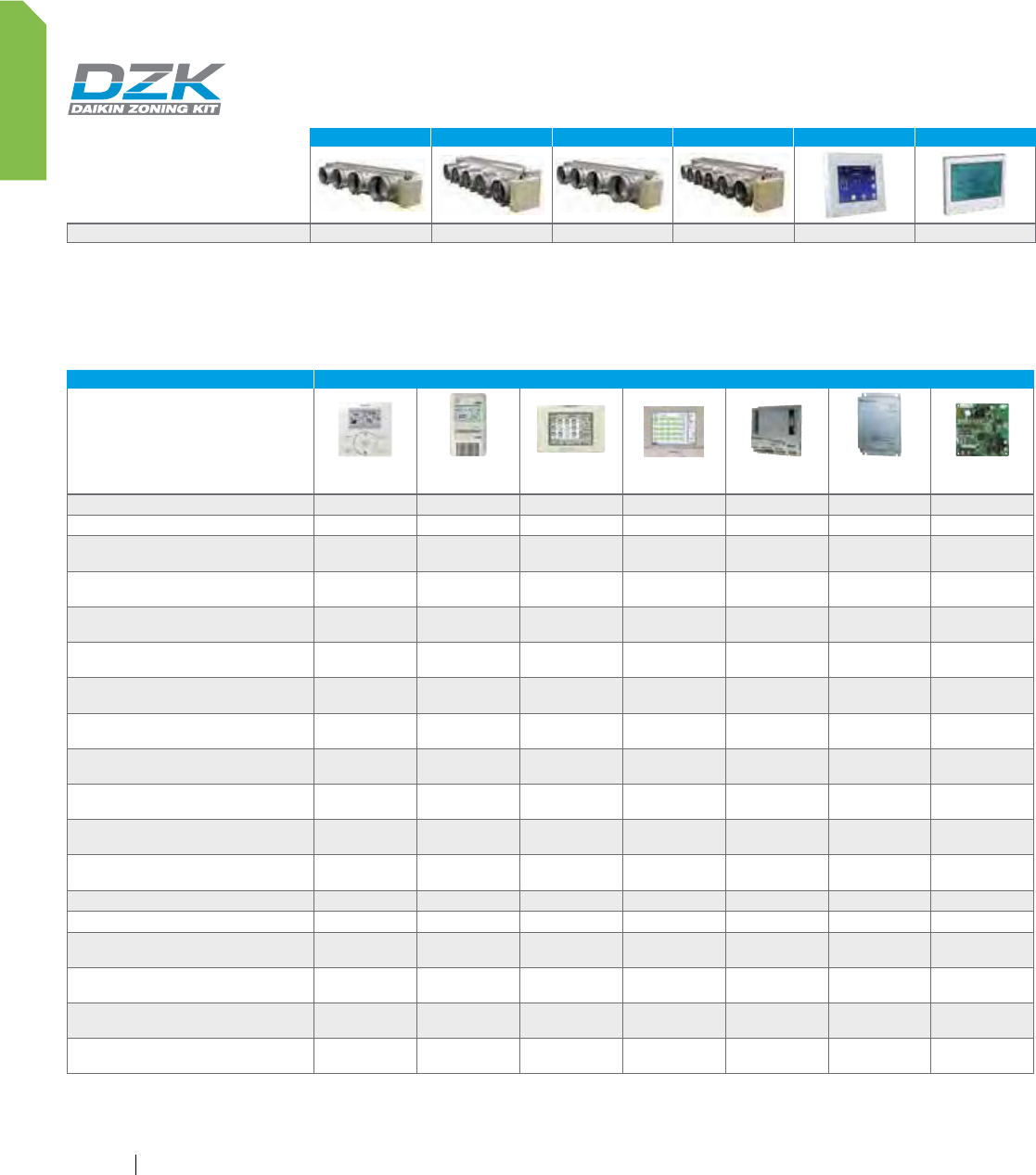
DZK (Daikin Zoning Kit)
The optional DZK increases the flexibility of the Daikin VRV and SkyAir systems in both residential and
commercial applications by adding a Zoning Box to an indoor unit fan coil (FXMQ-P or FBQ-P series,
respectively) allowing several separate ducts to supply air to different individually controlled zones.
DZK030E4 DZK030E5 DZK048E4 DZK048E6 DZK-MTS DZK-ZTS
Number of Air Duct Outlets x Diameter (") 4 x Ø8 5 x Ø6 4 x Ø8 6 x Ø6 – –
Daikin VRV controls
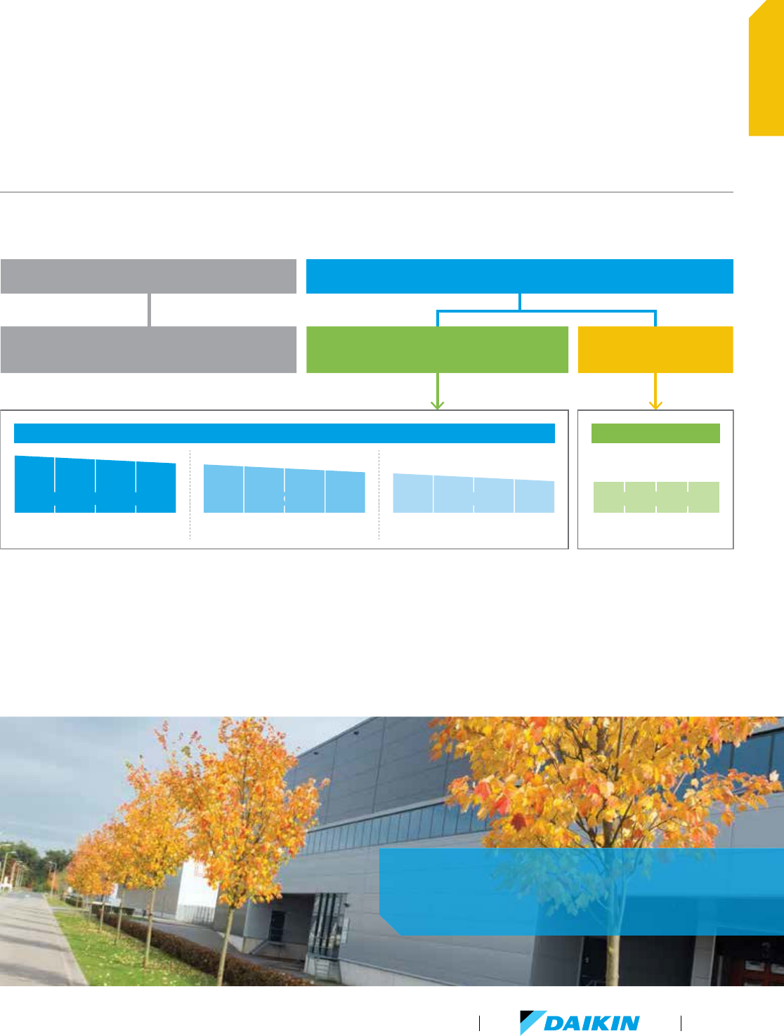
Optimized for VRV technology, Daikin controls provide highly scalable solutions for all applications and budgets. VRV controls offer
solutions to meet your project controls needs from individual zone control with local controllers to centrally controlling the building
with Centralized Controllers and/or interfacing with Building Management Systems (BMS) for comfort control in an easily managed
and operated system.
PROJECT REQUIREMENTS DAIKIN VRV CONTROLS
Navigation
Remote Controller
Simplified Remote
Controller
intelligent
Touch Controller
intelligent
Touch Manager
BACnet
Interface
LonWorks
Interface
Modbus
Interface
Individual zone control
l l
Independent cool and heat setpoints
l l l
Individual zone control with weekly
programmable scheduling
l l l
Basic central point on/off control of all
air handling units
l l l l l
Advanced multi-zone control of small to
medium size projects
l l l l l
Advanced multi-zone control of large
commercial projects
l l l l
Advanced multi-zone control with scheduling
logic and calendar
l l
Automatic cooling/heating changeover
for heat pump systems
l l l
Single input batch shutdown of all connected
air handlers
l l l l
n
Web browser control and monitoring
via Intranet and Internet
l l
n n n
E-mail notification of system alarms and
equipment malfunctions
l l
n n n
Multiple tenant power billing for shared
condenser applications
l l
Temperature set-point range restrictions
l l l
n n n
Graphical user interface with floor plan layout
l
n n n
Start/stop control of ancillary
building systems
*
l l
n n n
Daikin VRV integration with BACnet
®
based
automation systems
l
Daikin VRV integration with LonWorks
®
based automation systems
l
Daikin VRV integration with Modbus based
automation systems
l
*
Requires one or more DEC102A51-US2 Digital Input/Output units or WAGO DO module (for use with iTM only).
l
Native application or feature for this device.
n
Dependent upon capabilities of the third party energy management system
34
PRODUCT PORTFOLIO
www.daikincomfort.com
The configurable display and operation buttons on the Navigation
Remote Controller will provide as much or as little control as the
installed VRV system requires.
VRV Product Catalog
35
PRODUCT PORTFOLIO
Product Portfolio (continued)
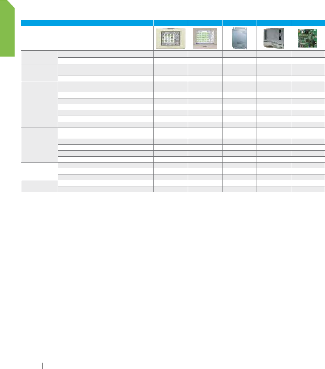
Network solutions
TYPE ITC ITM LONWORKS BACnet MODBUS
Screen
Layout screen
Touch screen
Integration
Mini BMS for heating, air conditioning applied systems
and refrigeration units (BACnet and WAGO)
3rd party equipment integration (BACnet and WAGO)
Control
Basic control functions: on/off, set point setting,
air flow settings, operation mode
Temperature limitation
Setback
Automatic changeover
Weekly schedule and special day pattern
Timer extension
Forced off
Monitoring
Basic control functions: ON/OFF status,
operation mode, set point temp.
Filter status
Malfunction code
History (operation, malfunction…)
Visualization
Options
PPD
Web access and control
Std
HTTP option
Other
Interlock
Maximum number of indoor unit groups 2 x 64 7 x 64 64 4 x 64 16
Accessories (continued)
36
PRODUCT PORTFOLIO
www.daikincomfort.com
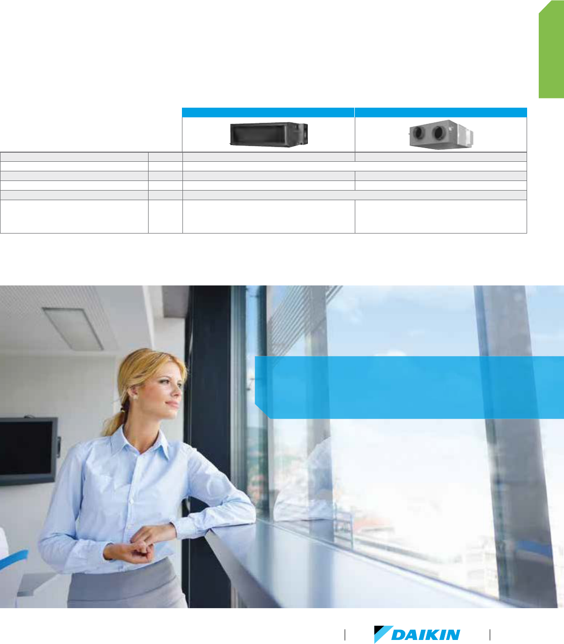
Air treatment systems
Daikin’s Outside Air Processing Unit can combine fresh air
treatment and air conditioning, supplied from a single system.
The compact Energy Recovery Ventilator is designed to improve
indoor air quality while reducing the overall HVAC system power
consumption. This is achieved by providing fresh outside air
and recovering waste heat from exhaust air leaving the
conditioned space.
OUTSIDE AIR PROCESSING UNIT, FXMQ-MFVJU ENERGY RECOVERY VENTILATOR, VAM-GVJU
VRV Refrigerant Piping Connectable Not connectable
VRV Control Wiring Connectable
High Efficiency Filter (MERV 8 and MERV 13) Option Not available
Ventilation System Air supply Air supply and Air exhaust
Power Supply V/ph/Hz 208-230/1/60
Airflow Rate CFM
635
988
1236
300/300/170
470/470/390
600/600/500
1200/1200/930
Daikin’s air treatment systems —
creating a better air quality environment.
VRV Product Catalog
37
PRODUCT PORTFOLIO
www.daikincomfort.com38
VRV Product Catalog
39
Indoor Units

As many as 64 separate indoor units can be connected to a refrigerant circuit with a single outdoor
unit of up to 38 tons capacity. The Daikin VRV indoor unit range is one of the widest on the market,
offering no less than 12 stylish and elegant indoor units types in 63 different models — all designed
to maximize comfort, minimize operating sound and simplify installation and servicing.
Indoor unit models include round flow ceiling mounted cassette,
ceiling concealed ducted, ceiling suspended, wall mounted and
floor standing models.
The Round Flow sensing cassette now includes an optional VRF
industry first self-cleaning filter, which automatically cleans itself
daily (user adjustable), leading to yearly energy savings of up to
50%. Dust from the filter is collected in the unit for easy and
quick removal (when indicated) with a standard vacuum cleaner.
Designed to fit rooms of any size and shape, Daikin indoor units
are also user friendly, ultra reliable, easy to control and quiet in
operation.
Indoor units
Designed for absolute comfort and versatility, Daikin's wide selection of
ducted and duct-free indoor units with a sleek and sophisticated design
provides zoning flexibility and comfort control for almost any application.
40
INDOOR UNITS
www.daikincomfort.com
INDOOR UNIT TYPE
CAPACITY
MBH 7.5 09 12 15 18 24 30 36 42 48 54 72 96
TONS 0.6 0.75 1 1.25 1.5 2 2.5 3 3.5 4 4.5 68
DUCTED
FXMQ-PBVJU
DC-Ducted Concealed Ceiling
(Medium Static)
FXDQ-MVJU
Slim Duct Built-In
Concealed Ceiling Unit
FXTQ-PAVJU
Vertical Air Handling Unit
(Horizontal RHS is Possible)
FXMQ-MVJU
Concealed Ceiling Unit
(Medium Static)
FXNQ-MVJU9 Concealed
Floor- Standing Unit
DUCT-FREE
FXFQ-TVJU
Round Flow Sensing Cassette,
Ceiling Mounted
NEW
FXUQ-PVJU
4-Way Blow
Ceiling-Suspended Cassette
FXZQ-MVJU9
2' X 2' 4-Way
Ceiling-Mounted Cassette
NEW
FXEQ-PVJU
Ceiling-Mounted Cassette
(Single Flow)
FXHQ-MVJU
Ceiling-Suspended Unit
FXAQ-PVJU
Wall-Mounted Unit
FXLQ-MVJU9
Floor-Standing Unit
Comfort cooling/heating (11 types 57 models)
Condensate pump standard
Outside air connection possible
VRV Product Catalog
41
INDOOR UNITS
Indoor units overview
What are your choices?
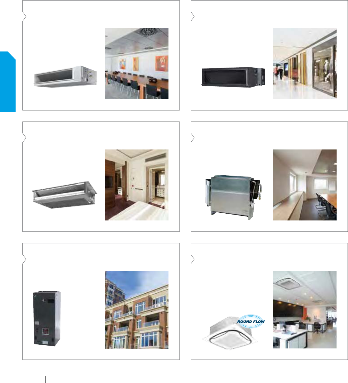
FXMQ-PBVJU
DC-Ducted Concealed Ceiling (Medium Static)
Ceiling mounted DC-Ducted
unit — ideal for small to large
spaces in need of a concealed
air-conditioning system.
FXMQ-MVJU
Concealed Ceiling Unit (Medium Static)
Ideal unit for larger open
space floor plans usually found
in offices, retails, hotels or
education facilities.
FXDQ-MVJU
Slim Duct Built-In Concealed Ceiling Unit
Slim duct built-in concealed
unit with low profile and low
sound level.
FXNQ-MVJU9
Concealed Floor- Standing Unit
Floor-standing unit that can easily
be installed along a perimeter
wall — or concealed.
FXTQ-PAVJU
Vertical Air Handling Unit (Horizontal RHS is Possible)
Vertical air handling unit ideal
for both residential and light
commercial applications. It has
both upflow
and horizontal
right installation
possibilities.
FXFQ-TVJU
Round Flow Sensing Cassette, Ceiling Mounted
Ideal for open plan applications
such as classrooms and offices
where adaptive comfort control
is preferred. Provides excellent
comfort level, energy efficiency,
and flexibility due to advanced
control functions.
42
INDOOR UNITS
www.daikincomfort.com
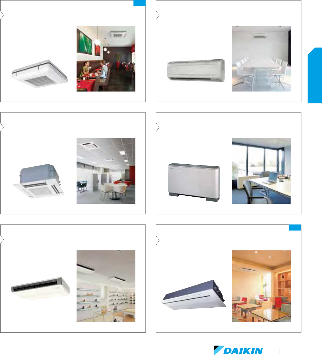
FXUQ-PVJU
4-Way Blow Ceiling-Suspended Cassette
Perfect solution for rooms
without a false ceiling, or minimal
space above a false ceiling,
where adaptive comfort control
is preferred.
FXAQ-PVJU
Wall-Mounted Unit
Unit ideal for cooling or heating
smaller zones such as stores,
offices and restaurants. Compact
and stylish design.
FXZQ-MVJU9
2'x2' 4-Way Ceiling-Mounted Cassette
2'x2' 4-way Cassette best for
open plan applications such as
classrooms, offices and retail.
FXLQ-MVJU9
Floor-Standing Unit
Great way to save space. The
floor-standing units can easily be
installed along a perimeter wall.
FXEQ-PVJU
Ceiling-Mounted Cassette
(Single Flow)
Slim and compact design for
installation flexiblity. For hotel
rooms, offices and residential.
FXHQ-MVJU
Ceiling-Suspended Unit
Ceiling-suspended with slim and
elegant design.
NEW
NEW
VRV Product Catalog
43
INDOOR UNITS
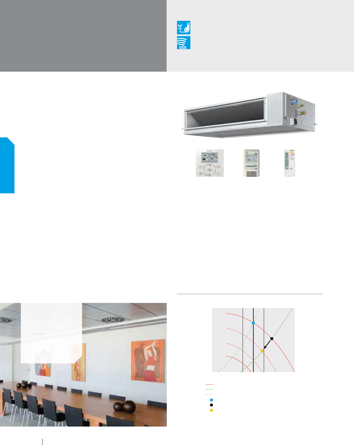
FXMQ-PBVJU
DC-Ducted Concealed
Ceiling Unit (Medium Static)
Powerful, Concealed, Flexible
The ceiling mounted DC-Ducted unit is ideal for small to large
spaces in need of a concealed air-conditioning system. It is
extremely powerful and the compact design allows it to be
completely concealed. This makes it perfect for retail, classrooms,
offices, banks, restaurants, shops and hotels common areas.
Features and Benefits
Capacity range up to 54 MBH.
Energy efficient due to the DC fan motor
Ideal to use together with the optional
Daikin Zoning Kit, DZK
Configurable auxiliary heater control logic
Advanced economizer control logic
Enhanced indoor air quality and LEED
ready with MERV 13 filter options
Ease of installation with auto adjusting airflow at
commissioning based on external static pressure
Flexible ductwork design with ESP
capabilities up to 0.8" W.G.
Installation flexibility with a low profile,
compact design at less than 12" in height
Easy maintenance with complete service access from below
Option to permanently turn off the
condensate pump via field settings
Airflow (cfm) ± 10%
Fan characteristic curve
Actual duct resistance curve
Duct resistance curve at the time of designing
Rated airflow
Airflow with out airflow automatic adjustment
Actual airflow
External static pressure
Condensate Pump
as Standard
Outside Air
Integration Possible
Applications
Offices
Hotels
Schools
Retail
BRC2A71 (option) BRC4C82 (option)BRC1E73 (option)
Auto Adjust External Static Pressure
After installation, it is possible that the actual duct resistance
is lower than expected at the time of designing. As a
consequence, the air-flow will be too high.
With the automatic air-flow adjustment function the unit can
adapt its fan speed to a lower curve, so the air-flow decreases.
The air-flow will always be within 10% of the rated air-flow
because of the amount of possible fan curves (more than 8
fan curves available per model).
Alternatively the installer can manually select a fan curve with
the wired remote control.
Auto Adjust External Static Pressure
44
INDOOR UNITS
www.daikincomfort.com
FXMQ-PBVJU
SPECIFICATIONS
0.6 TON 0.75 TON 1.0 TON 1.25 TON 1.5 TON 2.0 TON 2.5 TON 3.0 TON 4.0 TON 4.5 TON
Model Name
FXMQ07PBVJU
FXMQ09PBVJU
FXMQ12PBVJU
FXMQ15PBVJU
FXMQ18PBVJU
FXMQ24PBVJU
FXMQ30PBVJU FXMQ36PBVJU FXMQ48PBVJU FXMQ54PBVJU
Power Supply V/ph/Hz 208-230/1/60
Rated Cooling
Capacity
BTU/h 7,500 9,500 12,000 15,000 18,000 24,000 30,000 36,000 48,000 54,000
Rated Heating
Capacity
BTU/h 8,500 10,500 13,500 17,000 20,000 27,000 34,000 40,000 54,000 60,000
Airflow Rate (H/M/L) CFM 317/264/229 450/410/388 560/530/500 635/582/529 688/618/565 1,094/953/812 1,130/953/812 1,377/1,165/988 1,624/1,377/1,130
Height in. 11-3/16
Width in. 21-5/8 27-9/16 39-3/8 55-1/8
Depth in. 27-9/16
Condensate Pump Lift in. 18-3/8
Sound Pressure
(H/M/L)
dB(A) 33/31/29 39/37/35 40/38/37 41/39/37 42/40/38 43/41/39 44/42/40 46/45/43
Condensate Pipe
Connection
in. O.D. 1-1/4
Pipe
Connections
Gas in. 1/2 (Flare) 5/8 (Flare)
Liquid in. 1/4 (Flare) 3/8 (Flare)
Refrigerant R-410A
Refrigerant Control Electronic Expansion Valve
Maximum Overcurrent
Protective Device
A 15
Minimum
Circuit Amps
A 0.6 1.4 1.5 1.6 1.8 2.8 2.9 3.4
Protection Devices Fuse and Fan Driver Overload Protector
External Finish Galvanized Steel Plate
External Static
Pressure (H/L)
in. W.G. 0.40/0.12 0.80/0.20 0.56/0.20
MERV 13 Filter Kit Option contains a MERV 13 filter, adapter frame and easy to follow
installation instructions and can be installed on the following models only:
Kit Model Indoor Unit
DACA-FXMQ12131K FXMQ07-09PBVJU
DACA-FXMQ14131K FXMQ12PBVJU
DACA-FXMQ30131K FXMQ15-24PBVJU
DACA-FXMQ48131K FXMQ30-54PBVJU
FXMQ-PBVJU ACCESSORIES
Model Name
FXMQ07PBVJU FXMQ09PBVJU
FXMQ12PBVJU
FXMQ15PBVJU
FXMQ18PBVJU
FXMQ24PBVJU
FXMQ30PBVJU
FXMQ36PBVJU FXMQ48PBVJU
FXMQ54PBVJU
Navigation Remote
Controller
*
BRC1E73
Simplified Wired
Remote Controller
*
BRC2A71
Wireless Remote
Controller
BRC4C82
Remote Sensor Kit KRCS01-4B
Wiring Adapter PCB
(interface with aux/
primary heater, humidifier,
O
A damper/fan)
KRP1C74
Group Control Adapter PCB
(connects to external BMS)
KRP4A71
*
Optional face plates available to provide a more intuitive user interface and disable specific functions
ENTHALPY ECONOMIZER (FIELD APPLIED ACCESSORY)
Model Indoor Unit
ECONMQ12P-8-1K (MERV 8 Filter)
FXMQ07-09PBVJU
ECONMQ12P-13-1K (MERV 13 Filter)
ECONMQ30P-8-1K (MERV 8 Filter)
FXMQ15-24PBVJUECONMQ30P-13-1K (MERV 13 Filter)
ECONMQ48P-8-1K (MERV 8 Filter)
ECONMQ48P-13-1K (MERV 13 Filter) FXMQ30-54PBVJU
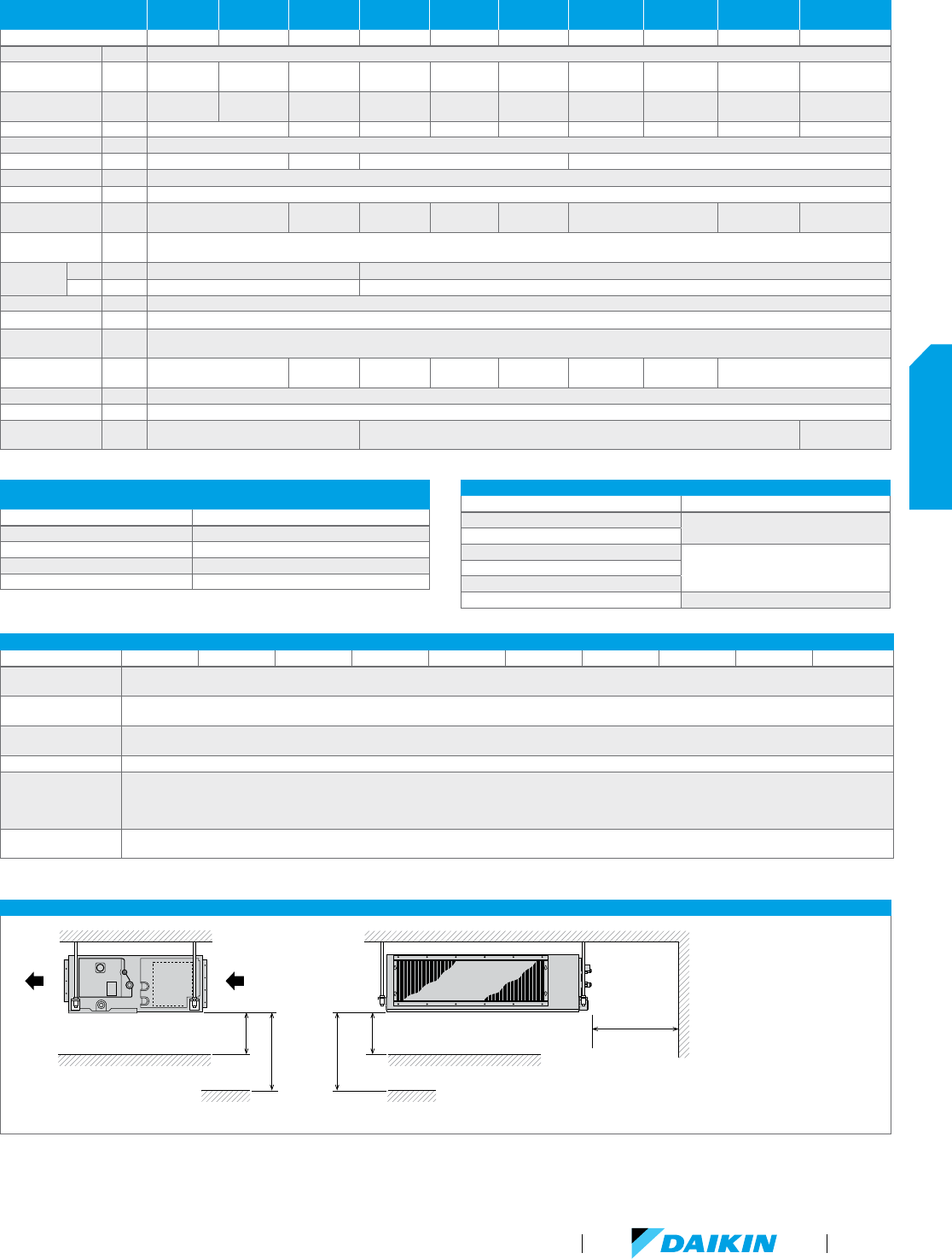
FXMQ-PBVJU INSTALLATION SPACE
a = 12" or more if one inspection
hatch (17-3/4" x 17-3/4") on the
control box side and a space of
11-13/16” or more under the unit.
a = 1" or more if an inspection
hatch the size of the indoor unit
plus an additional 12" or more on
the control box side is installed.
Ceiling
Floor Surface
Air
Outlet
Air
Inlet
a
99" or more
if no ceiling
a
Ceiling
18" or more
Floor Surface
99" or more
if no ceiling
VRV Product Catalog
45
INDOOR UNITS
Kits and Accessories
The optional Daikin Zoning Kit (DZK)
increases the flexibility of the Daikin
VRV and SkyAir systems by adding a
Zoning Box to an indoor unit fan coil (FXMQ–P or FBQ–P series,
respectively) allowing several separate ducts to supply air to
different individually-controlled zones in the building. A zone
can be a room, part of room, or several rooms. This flexible and
scalable Zoning Kit integrates seamlessly with the indoor unit
fan coil controls. The DZK system controls work together with
the regular Daikin zone controller (i.e. BRC1E73) to establish the
required set-point, fan speed and mode of operation that is then
requested to the VRV indoor unit via the Daikin zone controller.
This allows the internal DZK control algorithms to look at the
number of zone dampers in operation, and at what position the
dampers need to be and adjust the VRV indoor unit operation
accordingly. The DZK system is not directly compatible with the
suite of Daikin centralized control options such as iTM and iTC.
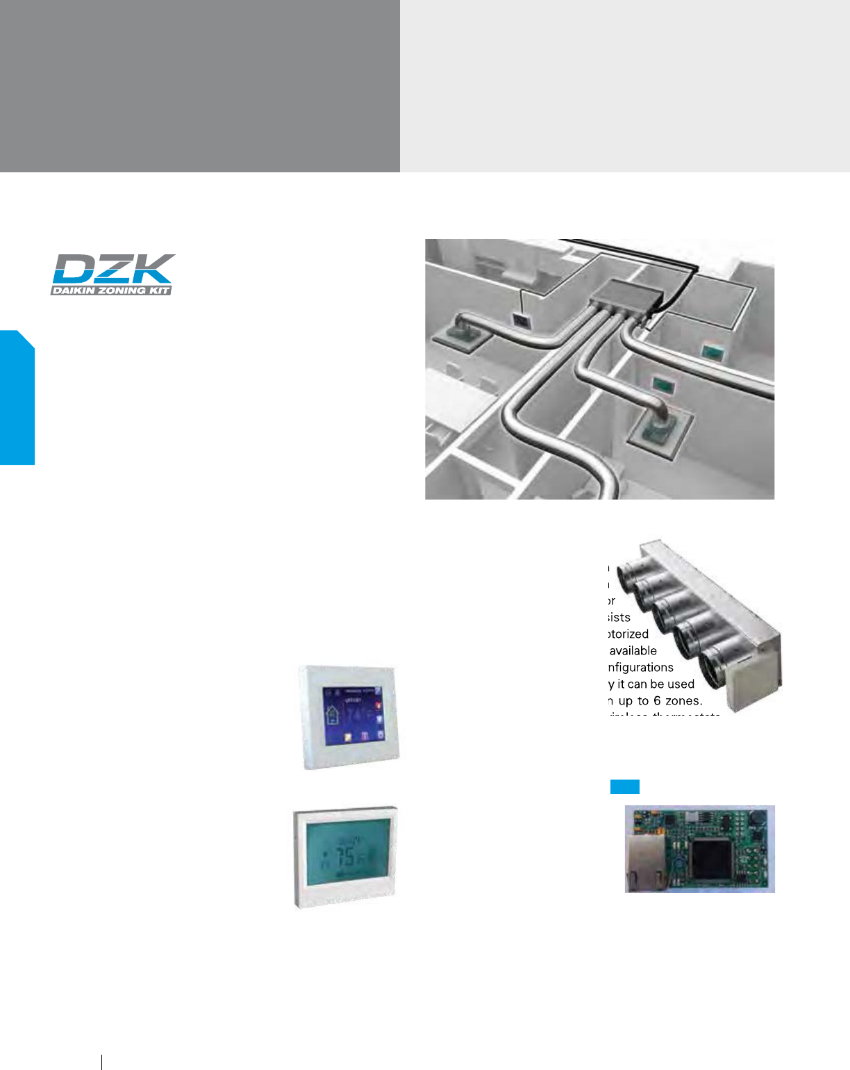
A complete Daikin Zoning Kit consists of Zoning Box (with Control
Board), Wired Thermostat, and Wireless Thermostats. The optional
DZK BACnet Gateway Module enables any BACnet/IP compatible
Building Management System to be used for remote monitoring
and control of the DZK.
Wired Thermostat
The Wired Thermostat in the DZK is a
graphical colored, touch-screen interface
with text menus, intuitive icons, and
guided scheduling capability. It displays
temperatures and operating values, and
selects the operating mode for the system.
Wireless Thermostat
The wireless backlit touch-screen
thermostat in the DZK can control the
temperature for a zone while displaying
the air temperature, system time, and day
of the week. Additional functions include
adjusting set point temperature, automatic
configuration, local ventilation activation,
and vacation mode. A wireless thermostat is required for zones
not being controlledby a wired thermostat.
Zoning Box with Control Box
(Model Depends on Indoor Unit)
The Zoning Box in the Daikin
Zoning Kit mounts easily on
Daikin’s Indoor Unit FXMQ–P or
FBQ-P series fan coils. It consists
of the enclosure, individually motorized
dampers, and a control box. It is available
in different sizes and damper configurations
and by utilizing ducts for air supply it can be used
to control the air temperature in up to 6 zones.
The wired thermostat and the wireless thermostats
provide temperature inputs and user interfaces for programming
and adjustment of the control functions for each zone.
DZK BACnet Gateway Module
If VRV systems are installed with the
DZK system to accomplish a variety
of zoning solutions and there is a
requirement to be able to monitor
and control the various DZK zone
dampers from a centralized control
system, it is possible to utilize the DZK BACnet Gateway module
to address this solution.
The DZK BACnet Gateway module will work with any BACnet/
IP compatible Building Management System.
The Wired Thermostat in the DZK is a
guided scheduling capability. It displays
temperatures and operating values, and
FXMQ-PBVJU (continued)
DC-Ducted Concealed
Ceiling Unit
(Medium Static)
The Zoning Box in the Daikin
Zoning Kit mounts easily on
Daikin’s Indoor Unit FXMQ–P or
FBQ-P series fan coils. It consists
of the enclosure, individually motorized
dampers, and a control box. It is available
in different sizes and damper configurations
and by utilizing ducts for air supply it can be used
to control the air temperature in up to 6 zones.
The wired thermostat and the wireless thermostats
Now with BACnet/IP compatibility
NEW
46
INDOOR UNITS
www.daikincomfort.com
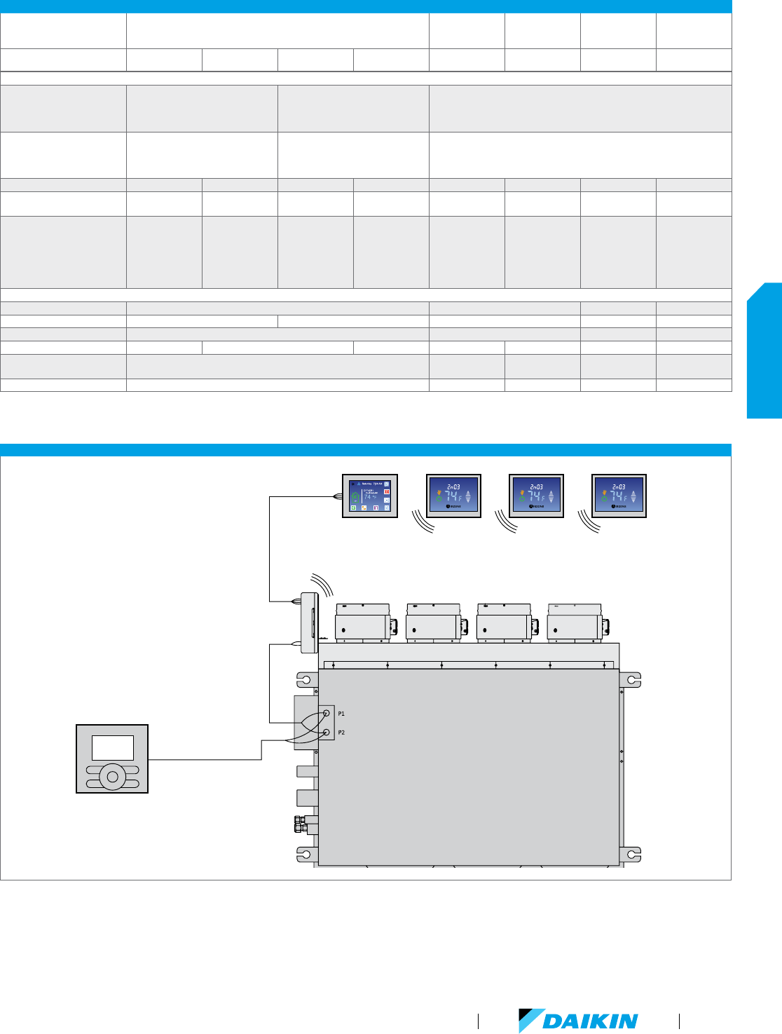
CONTROLS CONNECTION OF FXMQ-PBVJU AND DZK (WITHOUT BACNET)
Wireless ThermostatsWired Thermostat
Indoor Unit Fan Coil
Zoning Box
Control Box
Zoning Box
Navigation
Remote Controller
Typical Zoning Kit Configuration — 4 Zones
DAIKIN ZONING KIT (DZK) – KIT STRUCTURE AND GENERAL TECHNICAL DATA
Zoning Box with Control Box
Wired
Thermostat
*
Wireless
Thermostat
*
BACnet Gateway
Heat Pump
Changeover
Master
DZK Product Number
DZK030E4,
DZK030E4-2*
DZK030E5,
DZK030E5-2*
DZK048E4,
DZK048E4-2*
DZK048E6,
DZK048E6-2*
DZK-MTS-1-W,
DZK-MTS-2-W*
DZK-ZTS-1-W,
DZK-ZTS-2-W*
DZK-BACNET-2 DZK-CM-1
Kit Structure
Compatible with Indoor
Unit Fan Coils
- FXMQ15-24PBVJU
- FBQ18-30PVJU
Yes No Yes
Compatible with Indoor Unit
Fan Coils
- FXMQ30-54PBVJU
- FBQ36-42PVJU
No Yes Yes
Number of Zones Compatibility Maximum 4 Maximum 5 Maximum 4 Maximum 6 - - - -
Number of Air Duct Outlets
x Diameter (")
4 x Ø8 5 x Ø6 4 x Ø8 6 x Ø6 - - - -
Required Quantity
One Per Indoor
Unit Fan Coil
D
ZK030E4-2
Required For
BACnet/IP
One Per Indoor
Unit Fan Coil
DZK030E5-2
Required For
BACnet/IP
One Per Indoor
Unit Fan Coil
DZK048E4-2
Required For
BACnet/IP
One Per Indoor
Unit Fan Coil
DZK048E6-2
Required For
BACnet/IP
Minimum One Per
Indoor Unit Fan Coil
DZK-MTS-2-W
Required For
BACnet/IP
Number Of Zones
Minus Number Of
Wired Thermostats
DZK-ZTS-2-W
Required For
BACnet/IP
One Per DZK Zoning
Box With BACnet/IP
One Per VRV HP
System, If 2 To 16
DZK Units
(without BACnet)
In The Same VRV
System
Technical Data
Height (") 10.43 3.58 1.6 1.75
Width (") 43.58 53.46 4.13 2.7 2.32
Depth (") 10.43 0.94 1.2 0.67
Weight (lb.) 18.04 20.24 23.32 0.4 0.46 0.063 0.065
Input Voltage 110/230 VAC
12 VDC, from
Zoning Box
2 AAA Batteries
12 VDC, from
Control Board
12 VDC, from
Zoning Box
Full Load Amps (A) 0.25 - - - -
**
“-2” in the Product Number indicates that the product has BACnet/IP functionality. For configuration of DZK systems with BACnet/IP functionality, only Product Numbers ending with “-2” or ”-2-W” can be used.
For configuration of DZK systems without BACnet, either products with, or without, the BACnet functionality can be used, even “mix and match”.
VRV Product Catalog
47
INDOOR UNITS
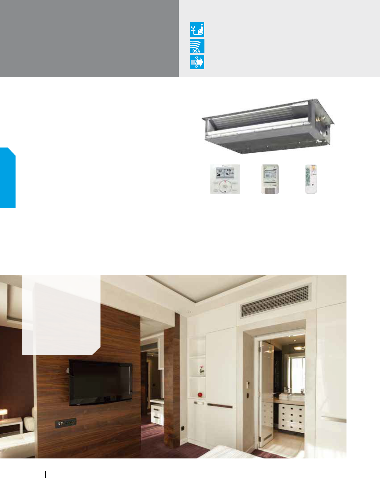
FXDQ-MVJU
Slim-Duct, Built-In
Concealed Ceiling Unit
Concealed, Slim, Quiet, Comfortable
The slim duct built-in concealed unit is available for use with the
VRV systems to complement the existing concealed ceiling unit
options. With its low profile and low sound level this unit can
be installed into limited ceiling void, bulkhead or soffit space.
Features and Benefits
Slim height, at only 7-7/8", makes it suitable for most of
the applications where attic / bulkhead space is limited
With a sound level down to 29 dB(A) these units
are among the quietest on the market
Factory shipped for rear air inlet —
field convertible to bottom air inlet
Washable filter included
Condensate pump with vertical lift of up
to 21-5/8" included as standard
Blends unobtrusively with any interior decor; only
the suction and discharge grills are visible
Condensate Pump
as Standard
Outside Air
Integration Possible
Filter
Included
Applications
Hotel rooms
Multi-family
residences
Single family
residences
School dormitories
BRC2A71 (option) BRC4C82 (option)BRC1E73 (option)
48
INDOOR UNITS
www.daikincomfort.com
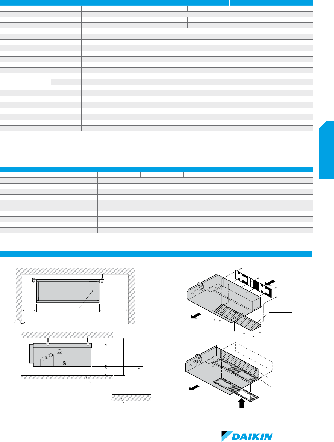
FXDQ-MVJU SPECIFICATIONS 0.6 TON 0.75 TON 1 TON 1.5 TONS 2 TONS
Model Name FXDQ07MVJU FXDQ09MVJU FXDQ12MVJU FXDQ18MVJU FXDQ24MVJU
Power Supply V/ph/Hz 208-230/1/60
Rated Cooling Capacity BTU/h 7,500 9,500 12,000 18,000 24,000
Rated Heating Capacity BTU/h 8,500 10,500 13,500 20,000 27,000
Airflow Rate (H/L) CFM 280/226 440/350 580/460
Weight lbs 51 63 71
Height in. 7-7/8
Width in. 27-9/16 35 -7/16 43-5/16
Depth in. 24-7/16
Sound Pressure (H/L) dB(A) 33/29 35/31 36/32
Condensate Pump Lift in. 21-5/8
Condensate Pipe Connection in. O.D. 1-1/32
Pipe Connections
Gas in. 1/2 (Flare) 5/8 (Flare)
Liquid in. 1/4 (Flare) 3/8 (Flare)
Refrigerant R-410A
Refrigerant Control Electronic Expansion Valve
Maximum Overcurrent Protective Device A 15
Minimum Circuit Amps A 0.9 1.3 1.4
Protection Devices Fuse and Fan Motor Thermal Protector
External Finish Galvanized Steel Plate
Standard Filter Type Removable, Washable, Mildew Proof
External Static Pressure (H/L) in. W.G. 0.12/0.04 0.17/0.06 0.17/0.06
FXDQ-MVJU ACCESSORIES
Model Name FXDQ07MVJU FXDQ09MVJU FXDQ12MVJU FXDQ18MVJU FXDQ24MVJU
Navigation Remote Controller
*
BRC1E73
Simplified Wired Remote Controller
*
BRC2A71
Wireless Remote Controller BRC4C82
Remote Sensor Kit KRCS01-1B
Wiring Adapter PCB (interface with aux/primary heater,
humidifier, OA damper/fan)
KRP1C75
Group Control Adapter PCB (connects to external BMS) KRP4A74
Access Panel (single door) APFXDQ070912 APFXDQ18 APFXDQ24
Access Panel with return air filter (single door) APRFFXDQ070912 APRFFXDQ18 APRFFXDQ24
Filter Media Replacement APRFFXDQ070912F APRFFXDQ18F APRFFXDQ24F
*
Optional face plates available to provide a more intuitive user interface and disable specific functions
FXDQ-MVJU INSTALLATION SPACE
Choose an installation site that ensures both optimum air distribution and sufficient clearance for maintenance.
The return air inlet can be easily changed from rear to bottom using the same chamber lid.
12"
or more
12"
or more
Control Box
Maintenance
Space
Maintenance
Space
Ceiling
Floor surface
(length : in.)
13/16" or more
7-7/8"
H = 9-1/2"
or more
100"or more
Nominal Conditions: Cooling Mode
Indoor: 80 °F DB / 67 °F WB
Outdoor: 95 °F DB
Pipe Length: 25 ft.
Level Difference: 0 ft.
H
eating Mode
Indoor: 70 °F DB
Outdoor: 47 °F DB / 43 °F WB
Pipe Length: 25 ft.
Level Difference: 0 ft.
No
te: Specifications are subject to change
without notice.
Chamber lid
Air inlet
Air discharge
Protection net
Chamber lid
Air inlet
Air discharge
Protection net
Chamber lid
Air inlet
Air discharge
Protection net
Chamber lid
Air inlet
Air discharge
Protection net
VRV Product Catalog
49
INDOOR UNITS
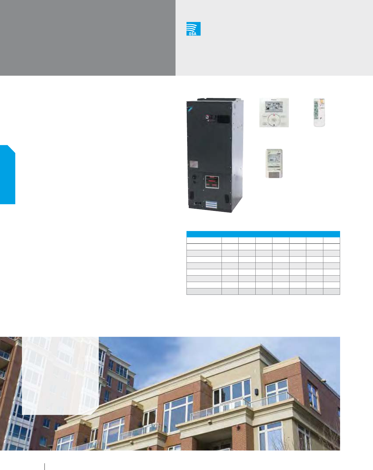
Concealed, Powerful, Compact, Comfortable
The vertical air handling unit is designed for use with all Daikin VRV
systems, allowing more flexibility and combination possibilities.
With a capacity range from 12 to 54 MBH and both upflow and
horizontal right installation possibilities, the unit is ideal for both
residential and light commercial applications.
Features and Benefits
Ideal replacement for fan coils, geothermal
heat pumps or traditional splits systems
Can be used in new construction or replacement projects
Ability to mix and match with other Daikin
indoor units on the same system
Reduced piping cost with smaller piping diameters
Upflow and horizontal right installation is permitted
2 selectable fan speeds (H and L)
New fan logic allowing the unit to be commissioned where
the fan operation will cycle on and off with the load
ECM fan motor provides energy efficiency
Wide line up of electric heat (field installed)
options from 3kW to 20kW
Plug-in electric heat control minimizes
equipment and installation cost
Possibility to operate electric heater in
combination with heat pump
FXTQ-PAVJU
Vertical Air
Handling Unit
Outside Air
Integration Possible
Applications
Offices
Hotels
Multi-family
residences
Single-family
residences
Electric Heater Options
ELECTRICAL HEATER CAPACITY
Model Name 3kW 5kW 6kW 8kW 10kW 15kW 20kW
FXTQ12PAVJU
nn
FXTQ18PAVJU
l nn
FXTQ24PAVJU
l nnnn
FXTQ30PAVJU
llnnn
FXTQ36PAVJU
llnnn
FXTQ42PAVJU
llllnn u
FXTQ48PAVJU
llllnn u n u
FXTQ54PAVJU
llllnn u n u
l Electric heater operation with heat
pump is allowed
n Only electric heater operation is allowed
N/A
u Acceptable 2 step heating operation
BRC2A71 (option)
BRC4C82 (option)BRC1E73 (option)
50
INDOOR UNITS
www.daikincomfort.com
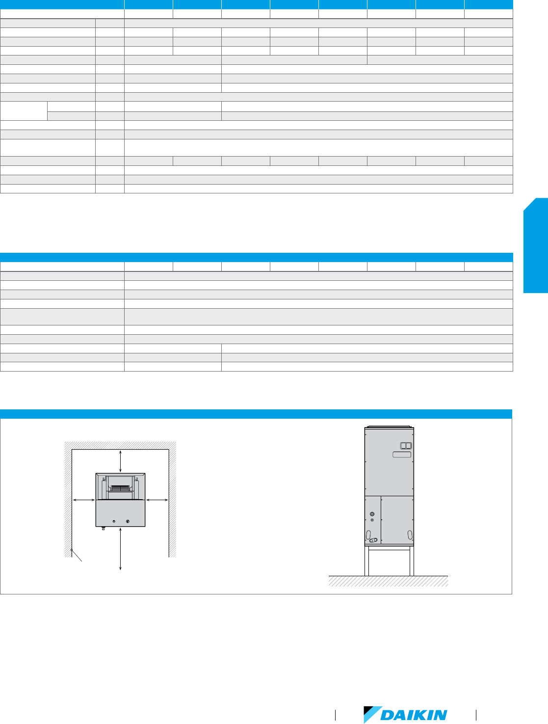
FXTQ-PAVJU SPECIFICATIONS 1 TON 1.5 TON 2 TON 2.5 TON 3 TON 3.5 TON 4 TON 4.5 TON
Model Name FXTQ12PAVJU FXTQ18PAVJU FXTQ24PAVJU FXTQ30PAVJU FXTQ36PAVJU FXTQ42PAVJU FXTQ48PAVJU FXTQ54PAVJU
Power Supply V/ph/Hz 208-230/1/60
Rated Cooling Capacity BTU/h 12,000 18,000 24,000 30,000 36,000 42,000 48,000 54,000
Rated Heating Capacity BTU/h 13,500 20,000 27,000 34,000 40,000 47,000 54,000 60,000
Airflow Rate (H/L) CFM 400/280 600/420 800/560 1,000/700 1,200/840 1,400/980 1,600/1,120 1,800/1,260
Weight lbs 119 145 167
Height in. 46-3/4 53-1/4
Width in. 19-1/2 22
Depth in. 22 24
Condensate Pipe Connection in. O.D. 3/4 (fpt)
Pipe
Connections
Gas in. 1/2 (Braze) 5/8 (Braze)
Liquid in. 1/4 (Braze) 3/8 (Braze)
Refrigerant R-410A
Refrigerant Control Electronic Expansion Valve
Maximum Overcurrent
Protective Device
A 15
Minimum Circuit Amps A 1.1 1.9 1.6 2.4 3.3 4.0 6.0 8.0
Protection Devices Fuse and Fan Motor Thermal Protector
External Finish Fully insulated, painted steel cabinet with gray finish
External Static Pressure Range in. W.G. 0.3 Standard, 0.5 Max
FXTQ-PAVJU ACCESSORIES
Model Name FXTQ12PAVJU FXTQ18PAVJU FXTQ24PAVJU FXTQ30PAVJU FXTQ36PAVJU FXTQ42PAVJU FXTQ48PAVJU FXTQ54PAVJU
Navigation Remote Controller
*
BRC1E73
Simplified Wired Remote Controller
*
BRC2A71
Wireless Remote Controller BRC4C82
Remote Sensor Kit KRCS01-4B
Group Control Adapter PCB
(connects to external BMS)
KRP4A742
External Control Adapter for Outdoor Unit DTA104A532
Fixing Box KRP1B1013
Air Filter FIL 36-42 FIL 48-61
Insulation Kit (vertical) DPI 36-42/20 DPI 48-61/-20
Insulation Kit (horizontal) DPIH 36-42 DPIH48-61
1
Need 24VAC power supply
2
Need 16VDC power supply
3
Fixing box installed beside the unit
*
Optional face plates available to provide a more intuitive user interface and disable specific functions
FXTQ-PAVJU INSTALLATION SPACE
12" or more
24" or more
Ceiling
12" or
more
12" or
more
Ensure there is sufficient space under the
unit so that return-air ductwork can be
installed and a downward slope of 1/100 can
be maintained for drain piping.
Nominal Conditions: Cooling Mode
Indoor: 80 °F DB / 67 °F WB
Outdoor: 95 °F DB
Pipe Length: 25 ft.
Level Difference: 0 ft.
H
eating Mode
Indoor: 70 °F DB
Outdoor: 47 °F DB / 43 °F WB
Pipe Length: 25 ft.
Level Difference: 0 ft.
No
te: Specifications are subject to change
without notice.
VRV Product Catalog
51
INDOOR UNITS
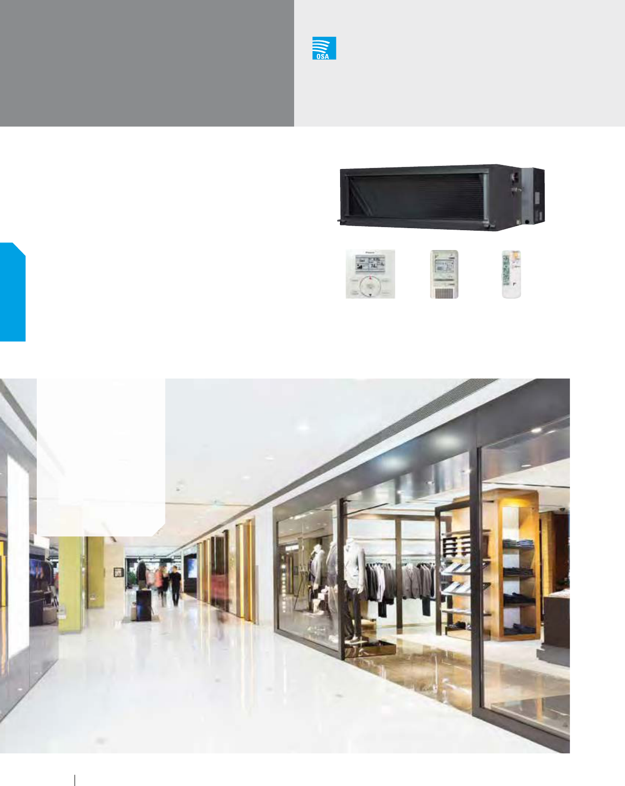
Concealed, Slim Design, Strong, Comfortable
The FXMQ-MVJU ducted fan coil unit is ideal for larger open space
floor plans usually found in offices, retails, hotels, or education
facilities. It performs well across multiple spaces that can benefit
from the same mode of operation, limiting equipment and
installation cost.
Features and Benefits
Design flexibility with a capacity range up to 96 MBH
Improved ductwork and filtration flexibility
with ESP capabilities of up to 1.1" W.G.
Low profile design of less than 19" high to
reduce required installation space
FXMQ-MVJU
Concealed
Ceiling Unit (Medium Static)
Outside Air
Integration Possible
Applications
Hotel/conference
centers
Schools
Retail/shopping
centers
Large open-plan
offices
Churches
BRC2A71 (option) BRC4C82 (option)BRC1E73 (option)
52
INDOOR UNITS
www.daikincomfort.com
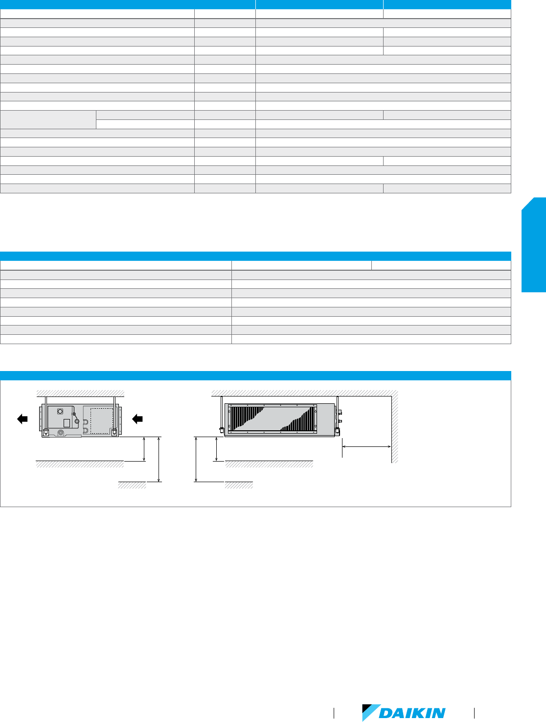
FXMQ-MVJU SPECIFICATIONS 6 TON 8 TON
Model Name FXMQ72MVJU FXMQ96MVJU
Power Supply V/ph/Hz 208-230/1/60
Rated Cooling Capacity BTU/h 72,000 96,000
Rated Heating Capacity BTU/h 81,000 108,000
Airflow Rate (H/L) CFM 2,047/1,764 2,541/2,188
Weight lbs 302
Height in. 18-1/8
Width in. 54-3/8
Depth in. 43-5/16
Sound Pressure (H/L) dB(A) 48/45
Condensate Pipe Connection in. O.D. 1
Pipe Connections
Gas in. 3/4 (Flare) 7/8 (Flare)
Liquid in. 3/8 (Flare)
Refrigerant R-410A
Refrigerant Control Electronic Expansion Valve
Maximum Overcurrent Protective Device A 15
Minimum Circuit Amps A 9.5 10.7
Protection Devices Fuse and Fan Motor Thermal Protector
External Finish Galvanized Steel Plate
External Static Pressure (Nominal/Maximum) in. W.G. 0.38/0.95 0.43/1.1
FXMQ-MVJU ACCESSORIES
Model Name FXMQ72MVJU FXMQ96MVJU
Navigation Remote Controller
*
BRC1E73
Simplified Wired Remote Controller
*
BRC2A71
Wireless Remote Controller BRC4C82
Remote Sensor Kit KRCS01-1B
Wiring Adapter PCB (interface with aux/primary heater, humidifier, OA damper/fan) KRP1C74
Group Control Adapter PCB (connects to external BMS) KRP4A71
High Efficiency Filter Kit (MERV 13) DACA-MQ96M-13-1K
High Efficiency Filter Kit (MERV 8) DACA-MQ96M-8-1K
*
Optional face plates available to provide a more intuitive user interface and disable specific functions
Nominal Conditions: Cooling Mode
Indoor: 80 °F DB / 67 °F WB
Outdoor: 95 °F DB
Pipe Length: 25 ft.
Level Difference: 0 ft.
H
eating Mode
Indoor: 70 °F DB
Outdoor: 47 °F DB / 43 °F WB
Pipe Length: 25 ft.
Level Difference: 0 ft.
No
te: Specifications are subject to change
without notice.
FXMQ-MVJU INSTALLATION SPACE
a = 12" or more if one inspection
hatch (17-3/4" x 17-3/4") on the
control box side and a space of
11 13/16" or more under the unit.
a = 1" or more if an inspection
hatch the size of the indoor unit
plus an additional 12" or more on
the control box side is installed.
Ceiling
Floor Surface
Air
Outlet
Air
Inlet
a
99" or more
if no ceiling
a
Ceiling
18" or more
Floor Surface
99" or more
if no ceiling
VRV Product Catalog
53
INDOOR UNITS
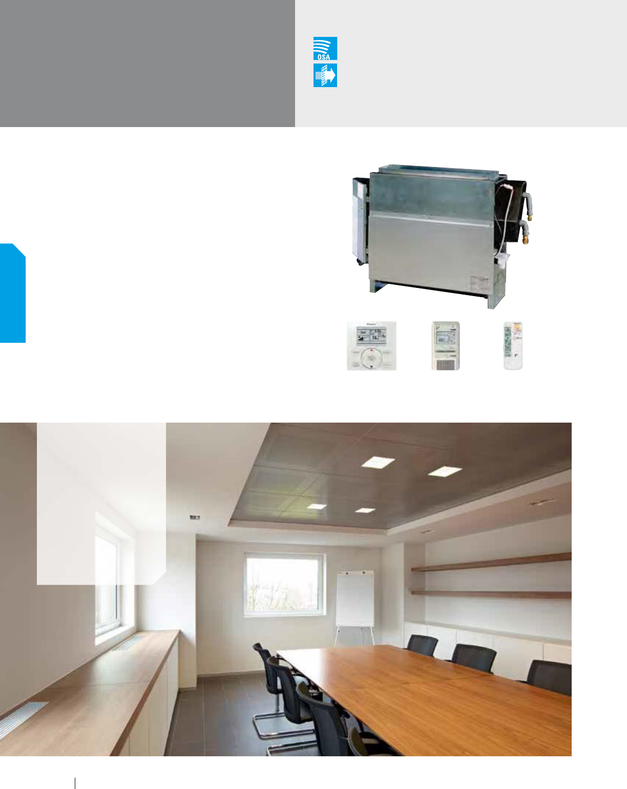
Versatile, Logical, Durable, Quiet
The ideal way to save space, our floor-standing units can
easily be installed along a perimeter wall — or concealed.
The air distribution from these models will allow you to find
the right balance for classrooms, churches, office hallways or
similar spaces. The concealed floor units cover a wide range of
capacities and can be built into counter in order to maintain the
aesthetics of the room.
Features and Benefits
Ideal for installation beneath a window
Unit requires minimal installation space
Fitted with a washable long-life filter
Remote-control options available
Space-saving unit can be freestanding or
wall-mounted, concealed or exposed
Models range from 7.5 MBH to 24 MBH
FXNQ-MVJU9
Concealed
Floor-Standing Unit
Outside Air
Integration Possible
Filter
Included
Applications
Multi-family
residences
Single-family
residences
Churches
Historic buildings
Schools
Offices
BRC2A71 (option) BRC4C82 (option)BRC1E73 (option)
54
INDOOR UNITS
www.daikincomfort.com
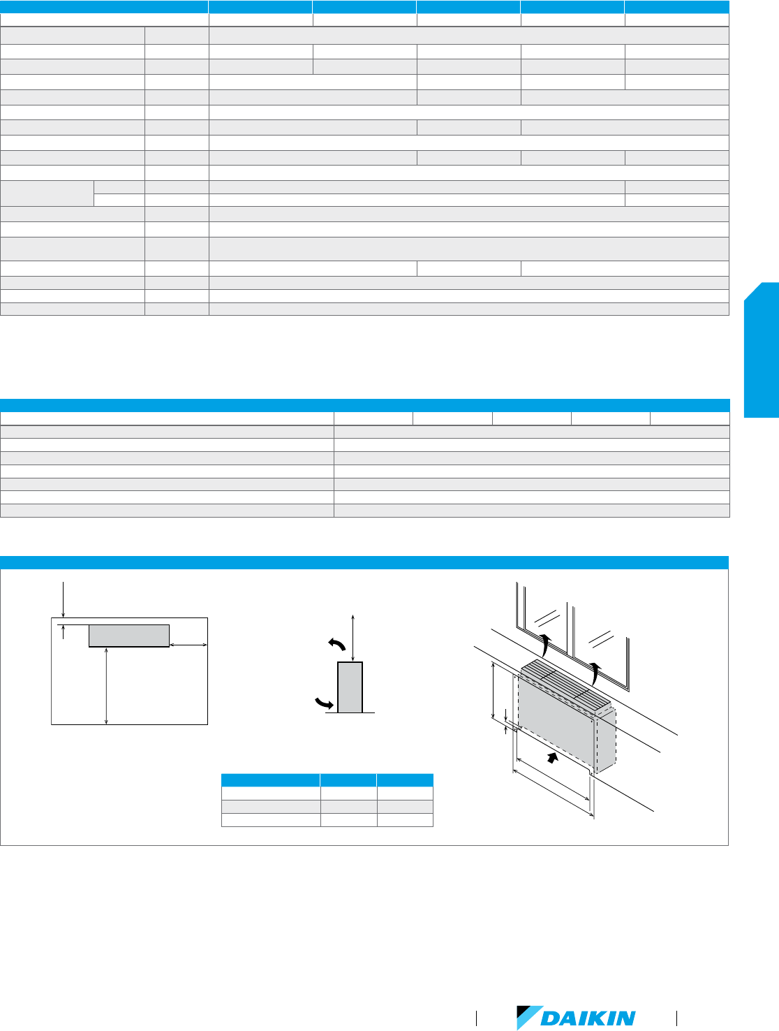
FXNQ-MVJU9 ACCESSORIES
Model Name FXNQ07MVJU9 FXNQ09MVJU9 FXNQ12MVJU9 FXNQ18MVJU9 FXNQ24MVJU9
Navigation Remote Controller BRC1E73
Simplified Wired Remote Controller
*
BRC2A71
Wireless Remote Controller BRC4C82
Remote Sensor Kit KRCS01-1B
Wiring Adapter PCB (interface with aux/primary heater, humidifier, OA damper/fan) KRP1C74
Group Control Adapter PCB (connects to external BMS) KRP4A71
Condensate Pump DACA-CP3-1
*
Optional face plates available to provide a more intuitive user interface and disable specific functions
FXNQ-MVJU9 INSTALLATION SPACE
6" or more
3/4" or
more
40" or more
Front
side
Base
70" or more
Air flow
direction
Air inlet
direction
IMPORTANT
Leave sufficient clearance for air inlet and maintenance.
Maintenance
area
3-1/8" or more
A or more
B or more
24-5/8"
MODEL A (IN.) B (IN.)
FXNQ12MVJU9 28 46
FXNQ18 - 24MVJU9 39 57
FXNQ07-09MVJU 23 41
FXNQ-MVJU9 SPECIFICATIONS 0.6 TON 0.75 TON 1 TON 1.5 TON 2 TON
Model Name FXNQ07MVJU9 FXNQ09MVJU9 FXNQ12MVJU9 FXNQ18MVJU9 FXNQ24MVJU9
Power Supply V/ph/Hz 208-230/1/60
Rated Cooling Capacity BTU/h 7,500 9,500 12,000 18,000 24,000
Rated Heating Capacity BTU/h 8,500 10,500 13,500 20,000 27,000
Airflow Rate (H/L) CFM 245/210 280/210 490/380 560/420
Weight lbs 47 51 60
Height in. 24
Width in. 36-5/8 42-1/8 53-1/8
Depth in. 8-5/8
Sound Pressure (H/L) dB(A) 35/32 36/33 40/35 41/36
Condensate Pipe Connection in. O.D. 27/32
Pipe Connections
Gas in. 1/2 5/8
Liquid in. 1/4 3/8
Refrigerant R-410A
Refrigerant Control Electronic Expansion Valve
Maximum Overcurrent
Protective Device
A 15
Minimum Circuit Amps A 0.3 0.5 0.6
Protection Devices Fuse and Fan Motor Thermal Protector
External Finish Galvanized Steel Plate
Standard Filter Type Resin Net (with Mold Resistant)
Nominal Conditions: Cooling Mode
Indoor: 80 °F DB / 67 °F WB
Outdoor: 95 °F DB
Pipe Length: 25 ft.
Level Difference: 0 ft.
H
eating Mode
Indoor: 70 °F DB
Outdoor: 47 °F DB / 43 °F WB
Pipe Length: 25 ft.
Level Difference: 0 ft.
No
te: Specifications are subject to change
without notice.
VRV Product Catalog
55
INDOOR UNITS
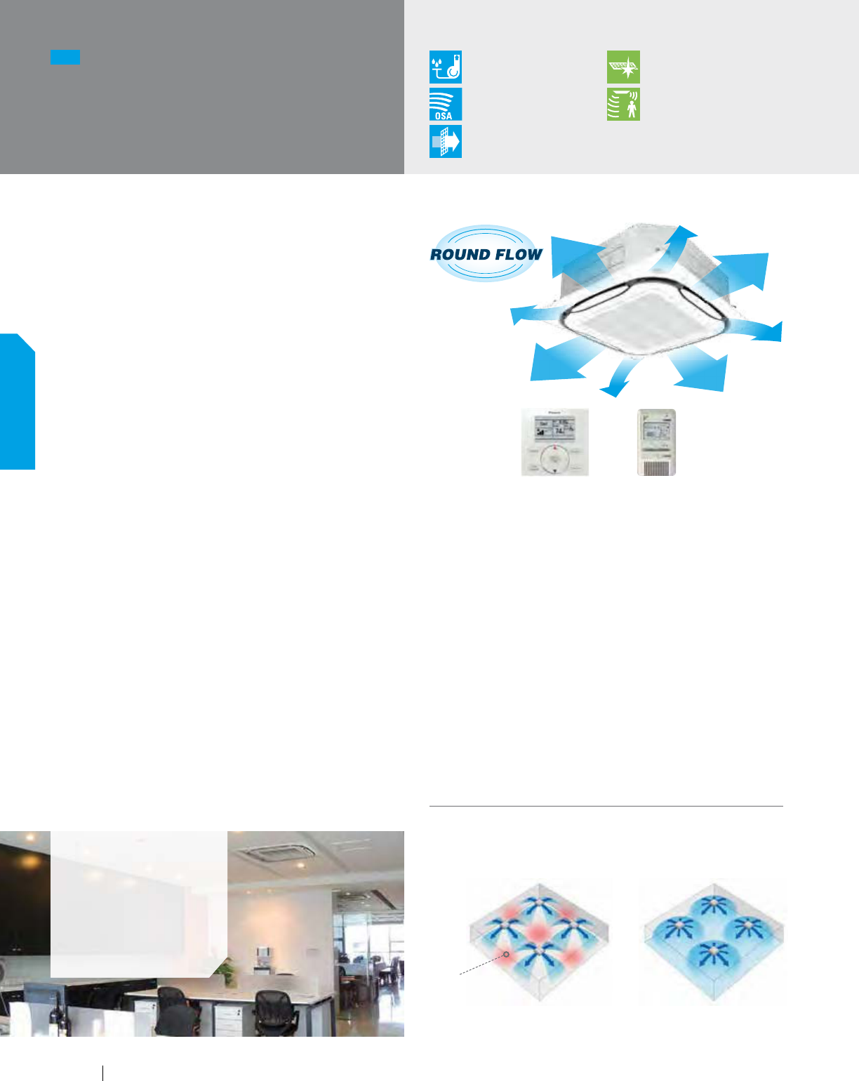
Adaptive Comfort Control
The Round Flow Sensing Cassette is ideal for open plan
applications such as classrooms and offices where adaptive
comfort control is preferred. The unit provides an excellent comfort
level, energy efficiency, and flexibility due to advanced control
functions based on input from three room sensors (occupancy,
air temperature, and surface temperature). With 18 configurable
airflow distribution patterns, it can be efficient and provide a
comfortable environment in smaller, more intricate spaces as well.
Features and Benefits
Capacity range from 7.5 to 48 MBH.
True 360° Airflow and three room sensors enables
optimized occupant comfort and efficiency
Energy efficient with DC fan motor and auto-logic
that adjusts fan speed based on space load
Optional self-cleaning air filter panel to further
increase efficiency and reduce maintenance
costs, when used in VRV IV systems
Very flexible with 18 different possible airflow
patterns, ensuring ideal air distribution to
maximize comfort and efficiency
Compact design to allow for installation in small ceiling voids
Sound pressure levels as low as 27 db(A)
Enhanced indoor air quality and LEED
ready with MERV 13 filter options
The built-in occupancy sensor has two main functions: save
energy and optimize occupancy comfort. In order to save energy,
the function of the occupancy sensor can be used to automatically
set back the air temperature and also lower the fan speed if no
people are present in the room.
NEW
FXFQ-TVJU
Round Flow
Sensing Cassette
Condensate Pump
as Standard
Optional
Auto Cleaning Filter
Outside Air
Integration Possible
Surface & Occupancy
Sensor Kit as Standard
Filter
Included
Applications
Retail
Schools
Offices
Restaurants
Together with the occupancy sensor, the air-temperature sensor
and the built-in surface temperature sensor are used to maintain
an even and comfortable temperature distribution from floor to
ceiling in the room. This is done by automatically adjusting the
supplied airflow rate and the individual position of each of the
four supply air louvers in the unit, thus maintaining the required
comfortable space environment.
In order to further increase efficiency and reduce maintenance
costs, the Round-Flow Sensing Cassette can be equipped with an
optional self-cleaning filter panel that performs automatic air-filter
cleaning up to once a day. Dust is deposited into a collection
box during the self-cleaning process. When indicated with light
on the unit and on the controller display, the dust collection box
in the unit can easily and quickly be emptied with a standard
vacuum cleaner.
BRC2A71 (option)BRC1E73 (option)
4-way flow vs. Round Flow
Areas of uneven
temperature
Much fewer
areas of uneven
temperature
4-way flow Round Flow
Round Flow Ceiling Mounted Cassette type offers 360˚ airflow with improved
temperature distribution.
56
INDOOR UNITS
www.daikincomfort.com
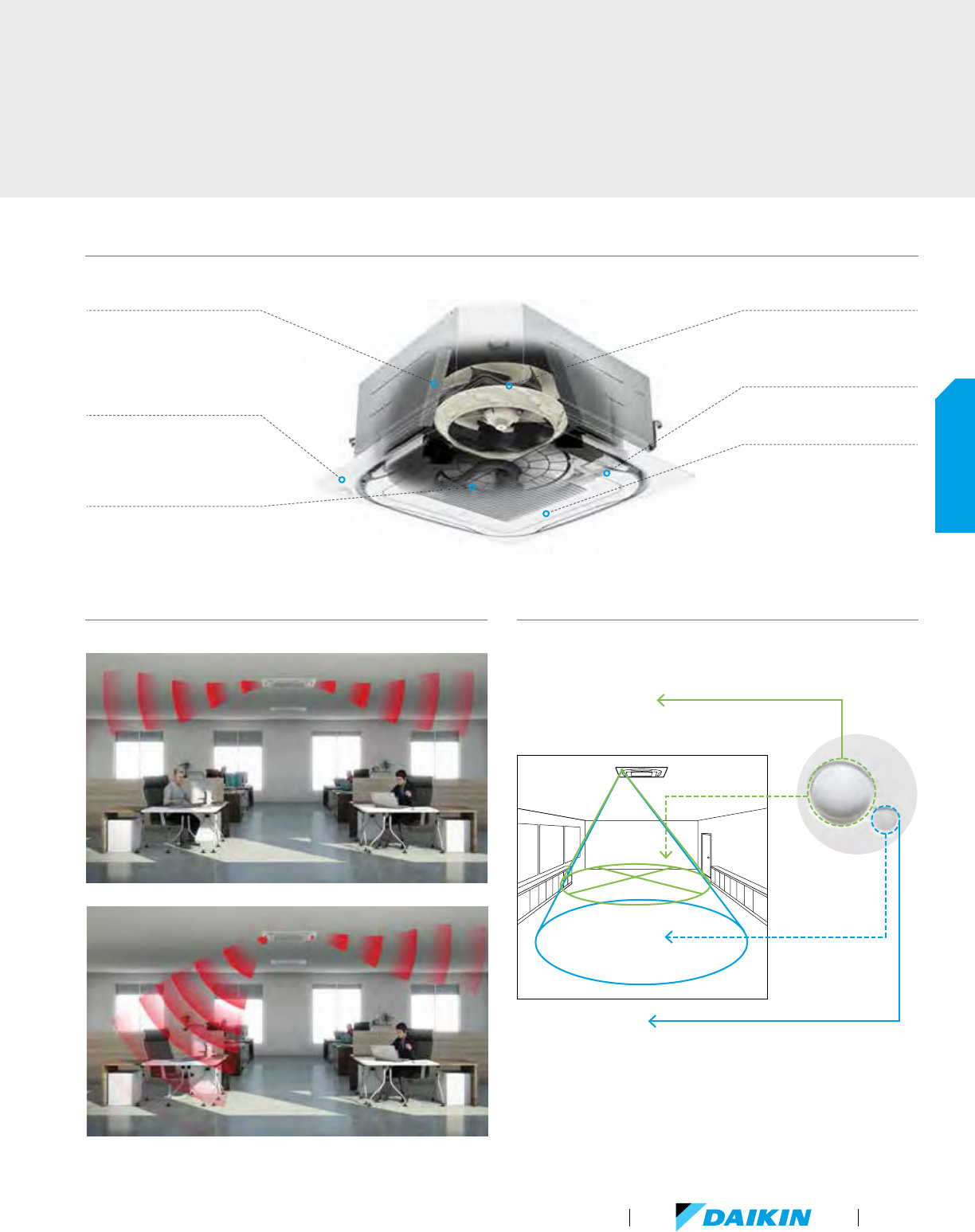
Air flow from the indoor unit is automatically adjusted to always maintain a
comfortable environment — even when occupancy changes.
Heat Exchanger Design
Optimized for part load operation
— great enhancement to seasonal
energy efficiency
Occupancy and Surface
Temperature Sensors
Enables additional energy savings
and increased comfort
Optional Self-Cleaning
Filter Panel
Provides optimum efficiency, airflow
and reduced maintenance
DC Fan Motor
Very efficient — enables fan auto
logic based on ∆T set point
DC Drain Pump
Low power consumption
Decoration Panel
Efficient due to large air
discharge outlets
Unique 360° airflow distribution
4 individually controlled louvers
enables optimized comfort in
the space
Possibility to close 1, 2 or 3
louvers adds flexibility
Automatic air-direction control
In
frared surface sensor
Th
e sensor detects the surface temperature and automatically adjusts operation
of
the indoor unit to reduce the temperature difference between the ceiling and
th
e floor.
Sensors detect the presence of people and surface temperature to provide
comfor
table air-conditioning and energy savings.
In
frared presence sensor
Th
e sensor detects human presence, and energy saving control
ca
n be performed when no people are detected.
Dual infrared sensors
Advanced design for comfort and efficiency
VRV Product Catalog
57
INDOOR UNITS
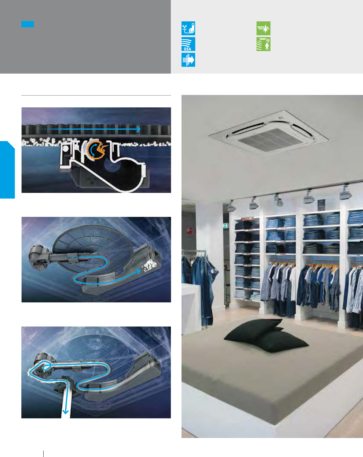
Dust from the air filter brush is deposited into the dust collection container
during the fully automatic self-cleaning process.
NEW
FXFQ-TVJU (continued)
Round Flow
Sensing Cassette
Condensate Pump
as Standard
Optional
Auto Cleaning Filter
Outside Air
Integration Possible
Surface & Occupancy
Sensor Kit as Standard
Filter
Included
Automatic air filter cleanining (optional)
At the programmed time, the air filter rotates while the air filter brush turns
back and forth to brush the filter.
When indicated, the dust container in the unit is easily emptied with a
standard vacuum cleaner.
Air filter
brush
Air filter
58
INDOOR UNITS
www.daikincomfort.com
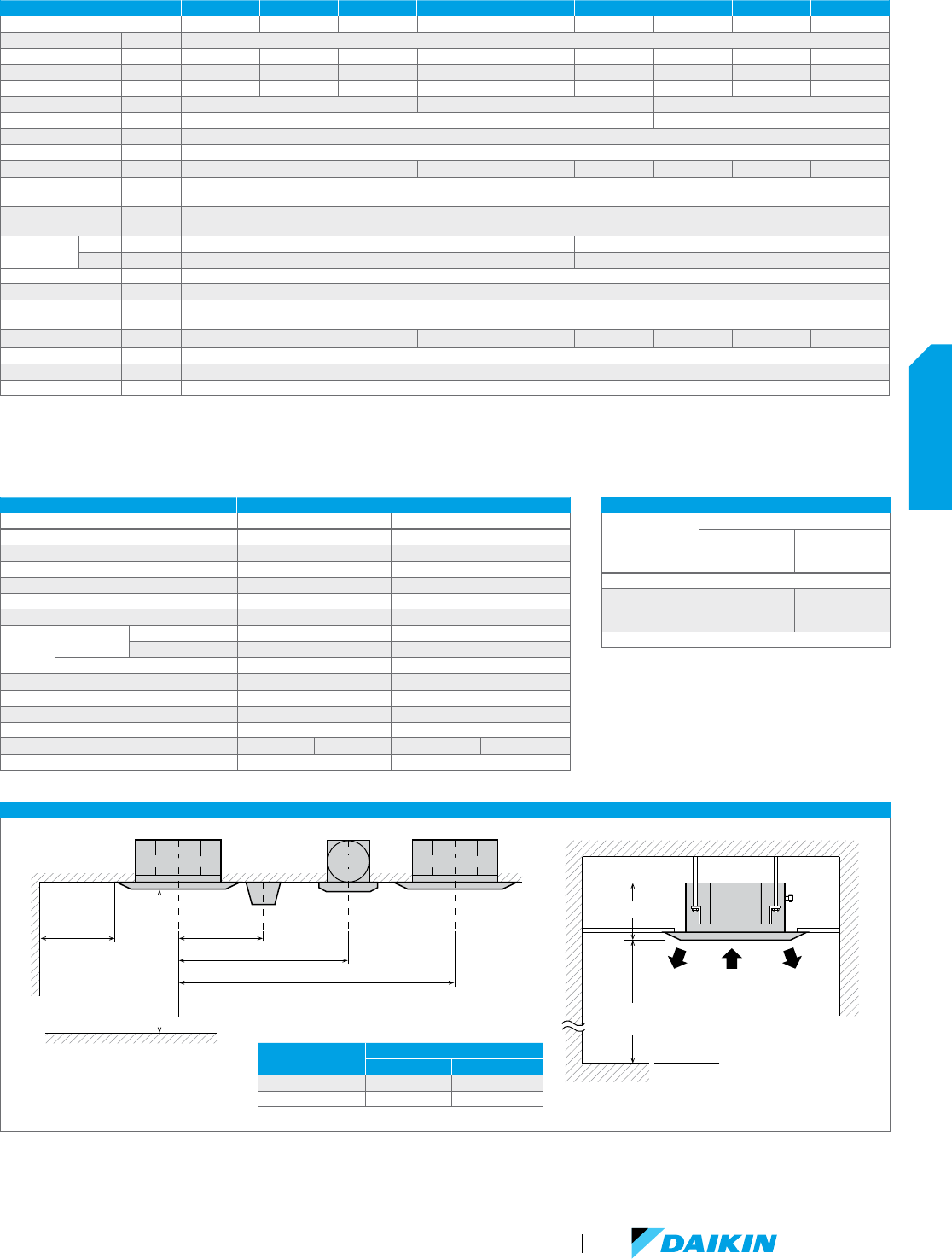
FXFQ-TVJU INSTALLATION SPACE
Nominal Conditions: Cooling Mode
Indoor: 80 °F DB / 67 °F WB
Outdoor: 95 °F DB
Pipe Length: 25 ft.
Level Difference: 0 ft.
H
eating Mode
Indoor: 70 °F DB
Outdoor: 47 °F DB / 43 °F WB
Pipe Length: 25 ft.
Level Difference: 0 ft.
No
te: Specifications are subject to change
without notice.
FXFQ-TVJU SPECIFICATIONS 0.60 TON 0.75 TON 1 TON 1.25 TON 1.5 TON 2 TON 2.5 TON 3 TON 4 TON
Model Name FXFQ07TVJU FXFQ09TVJU FXFQ12TVJU FXFQ15TVJU FXFQ18TVJU FXFQ24TVJU FXFQ30TVJU FXFQ36TVJU FXFQ48TVJU
Power Supply (V/ph/Hz) 208-230/1/60
Rated Cooling Capacity BTU/h 7,500 9,500 12,000 15,000 18,000 24,000 30,000 36,000 48,000
Rated Heating Capacity BTU/h 8,500 10,500 13,500 17,000 20,000 27,000 34,000 40,000 54,000
Airflow Rate (H/M/L) CFM 420/406/353 441/406/353 441/406/353 512/459/388 742/618/477 777/618/477 1,112/918/671 1,165/918/671 1,218/971/742
Weight lbs 42 48 58
Height in. 9-11/16 11-5/16
Width in. 33-1/16
Depth in. 33-1/16
Sound Pressure (H/M/L) dB(A) 30/28.5/27 31/29/27 35.5/32/28 36/32/28 43.5/38/32 44/38/32 45/40/35
Condensate
Pump Lift
in. 33-1/2
Condensate Pipe
Connection
in. O.D. 1-1/4
Pipe
Connections
Gas in. 1/2 (Flare) 5/8 (Flare)
Liquid in. 1/4 (Flare) 3/8 (Flare)
Refrigerant R-410A
Refrigerant Control Electronic Expansion Valve
Maximum Overcurrent
Protective Device
A 15
Minimum Circuit Amps A 0.3 0.4 0.6 0.7 1.3 1.5 1.8
Protection Devices Fuse/Breaker and Fan Motor Thermal Protector
External Finish Galvanized Steel Plate
Standard Filter Type Mold-Resistant Resin Net
OUTDOOR / CONDENSING UNIT COMPATIBILITY
Outdoor
Condensing Unit
FXFQ-TVJU with:
Self-Cleaning
Filter Panel
(BYCQ125BGW1)
Standard Sensing
Decoration Panel
(BYCQ125B-W1)
VRV IV Yes
VRV III,
VRV IV W-Series,
VRV III-S
No Yes
SkyAir No
OPTION FXFQ09-48TVJU
Type of panel Self-Cleaning Filter Panel Standard Sensing Decoration Panel
Self-Cleaning Filter Panel BYCQ125BGW1 -
Connection pipe (for dust recovery) KKHAP55B160 -
L-shape extension pipe KKHAP55A160 -
Standard Sensing Decoration Panel - BYCQ125B-W1
Sealing material for air discharge outlet KDBH55K160F KDBHQ55B140
Panel spacer KDBP55H160FA KDBP55H160FA
Fresh air
intake kit
Chamber type
Without T shape pipe - KDDQ55B140
With T shape pipe - KDDP55B160K
Direct installation type - KDDP55X160
Filter chamber - KDDFP55B160
Replacement long life filter - KAFP55B160
Replacement ultra long life filter - KAFP55H160H
Self-Cleaning Filter Panel replacement filter KAFP554A160 -
Branch duct chamber KDJP55B80 KDJP55B160 KDJP55B80 KDJP55B160
MERV 13 Filter Kit - DACA-FQP13-1K
SuctionDischargeDischarge
Floor level
At least 70"
from a floor
(A)
Lighting
60" or more
from a wall
60" or more
80" or more
160" or more
Obstacles
At least 60" from any fixture
Indoor unitIndoor unit Indoor unitIndoor unit
Exhaust
fan
Exhaust
fan
MODEL NAME
(FXFQ-T VJU)
A (IN.)
BYCQ125B-W1 BYCQ125BGW1
07 · 09 · 12 · 15 · 18 · 24 10 13-1/4
30 · 36 · 48 11-3/4 14-7/ 8
SuctionDischargeDischarge
Floor level
At least 70"
from a floor
(A)
Lighting
60" or more
from a wall
60" or more
80" or more
160" or more
Obstacles
At least 60" from any fixture
Indoor unitIndoor unit Indoor unitIndoor unit
Exhaust
fan
Exhaust
fan
VRV Product Catalog
59
INDOOR UNITS
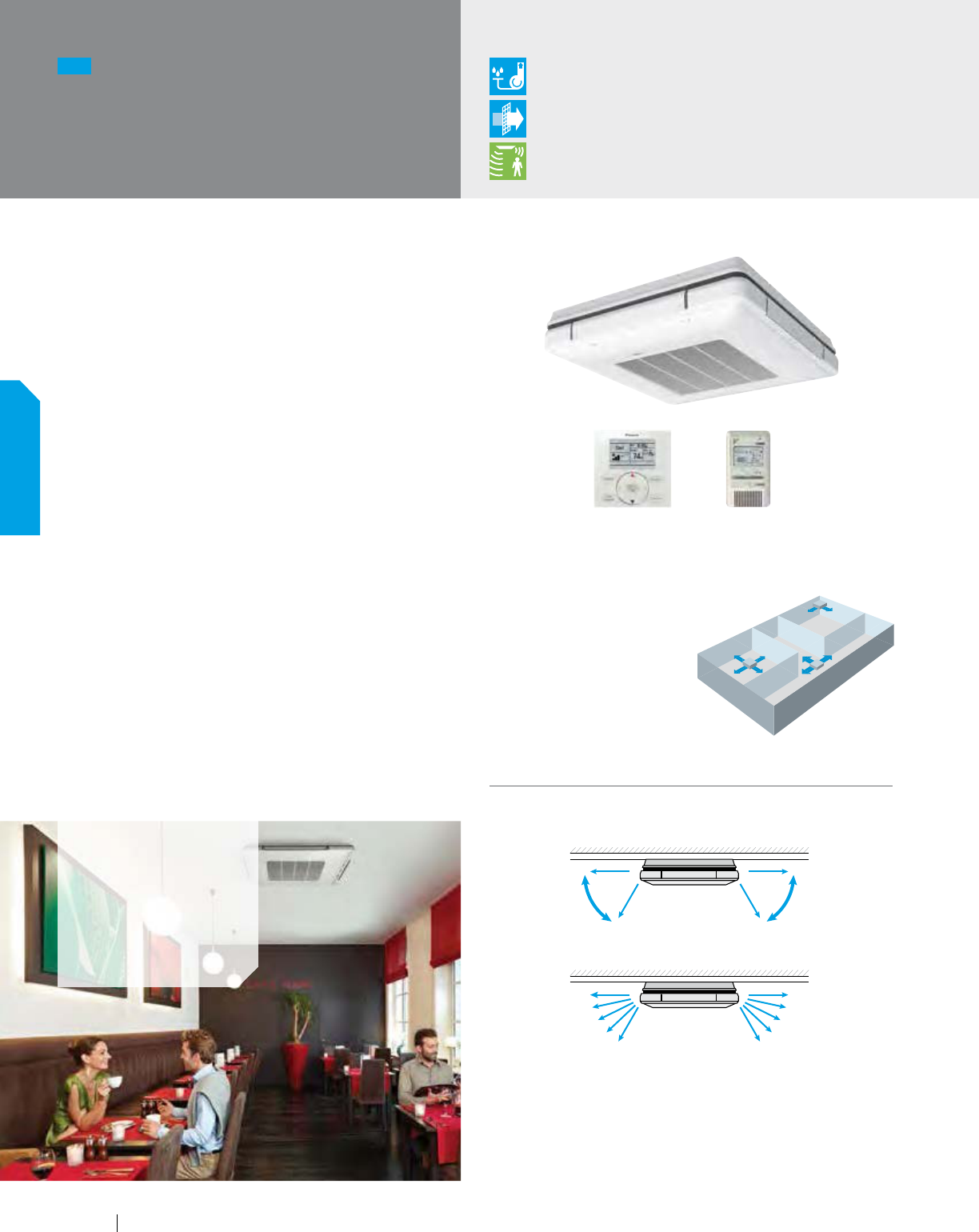
Slim, Stylish, Flexible
The unique 4-way ceiling-suspended cassette is an ideal solution
for rooms without a false ceiling, or minimal space above a false
ceiling, where adaptive comfort control is preferred.
The optional Sensor Kit (occupancy and surface temperature)
together with air temperature sensor and advanced control
functions enables the unit to provide an exceptional comfort
level, energy efficiency, and flexibility.
Features and Benefits
Very low unit height of under 8" makes it an
ideal solution for school, shops, restaurants
and offices with no or low false ceilings
Optional Sensor Kit enables input from three room sensors
to provide optimized occupant comfort and efficiency
Stylish unit blends easily with any interior, as the
air louvers close entirely when not in operation
Energy efficient fan motor
Individual air louver control — one or more louvers can
be easily closed via the remote controller when required
Ideal for both new and existing buildings
Can also be mounted partially recessed in a false ceiling
Same appearance and size for all capacity models
Standard drain pump with 19.5" lift
NEW
FXUQ-PVJU
4-Way Ceiling-Suspended
Cassette
Applications
Retail
Schools
Offices
Restaurants
0°
Auto Swing: Wide discharge angle: 0° to 60°
60°60°
0°
0°
60°60°
0°
Fixed angles: 5 levels
Condensate Pump
as Standard
Filter
Included
Optional Surface &
Occupancy Sensor Kit
Flexible Airflow Pattern
The four individually controlled air louvers
in the unit enables comfortable space
environment in a variety of
different room layouts.
Air from each louver can be set
to exhaust in 5 different angles
between 0 and 60 degrees, or set to
auto-swing.
BRC2A71 (option)BRC1E73 (option)
Airflow Angles
60
INDOOR UNITS
www.daikincomfort.com
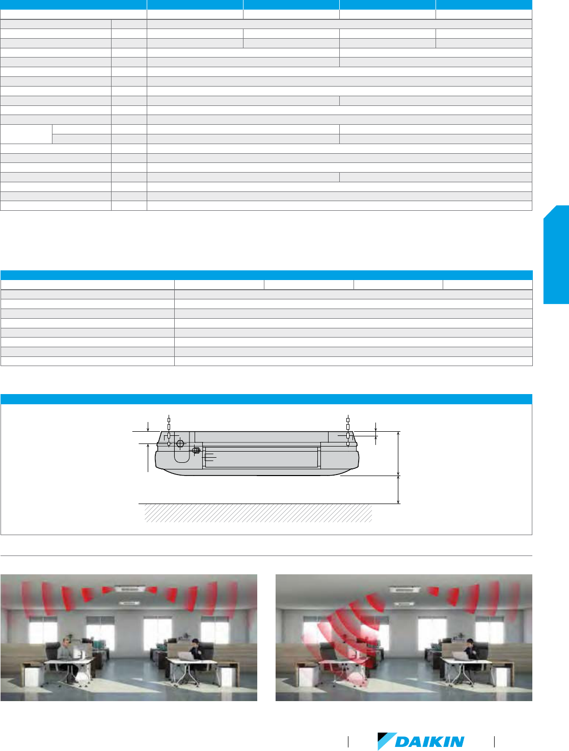
FXUQ-PVJU INSTALLATION SPACE
2-1/4"
7-13/16"
13/16"
100" or more
(Required space)
Nominal Conditions: Cooling Mode
Indoor: 80 °F DB / 67 °F WB
Outdoor: 95 °F DB
Pipe Length: 25 ft.
Level Difference: 0 ft.
H
eating Mode
Indoor: 70 °F DB
Outdoor: 47 °F DB / 43 °F WB
Pipe Length: 25 ft.
Level Difference: 0 ft.
No
te: Specifications are subject to change
without notice.
FXUQ-PVJU SPECIFICATIONS 1.5 TON 2 TON 2.5 TON 3 TON
Model Name FXUQ18PVJU FXUQ24PVJU FXUQ30PVJU FXUQ36PVJU
Power Supply (V/ph/Hz) 208-230/1/60
Rated Cooling Capacity BTU/h 18,000 24,000 30,000 36,000
Rated Heating Capacity BTU/h 20,000 27,000 34,000 40,000
Airflow Rate (H/M/L) CFM 795/689/565 1095/918/742
Weight lbs 58 60
Height in. 7-13/16
Width in. 37 3/8
Depth in. 37 3/8
Sound Pressure (H/M/L) dB(A) 40/38/36 47/44/40
Condensate Pump Lift in. 19.5
Condensate Pipe Connection in. O.D. VP20
Pipe
Connections
Gas in. 1/4 (Flare) 3/8 (Flare)
Liquid in. 1/2 (Flare) 5/8 (Flare)
Refrigerant R-410A
Refrigerant Control Electronic Expansion Valve
Maximum Overcurrent Protective Device A 15
Minimum Circuit Amps A 0.6 1.4
Protection Devices Fuse and Fan Motor Thermal Protector
External Finish White Casing
Standard Filter Type Resin Net (with Mold Resister)
FXUQ-PVJU ACCESSORIES
Model Name FXUQ18PVJU FXUQ24PVJU FXUQ30PVJU FXUQ36PVJU
Sealing Member of Air Discharge Outlet KDBHP49B140
Decoration Panel for Air Discharge KDBTP49B140
Replacement Long-Life Filter KAFP551K160
Remote Control (wired type) BRC1E73
Sensor Kit
2
BRE49B1F
Group Control Adapter Printed Circuit Board
1
KRP4A74
Installation Box for Adapter PCB KRP1BA97
Remote Sensor
2
KRCS01-48
¹ Installation box for Adapter PCB (KRP1BA97) is necessary. ² Remote Sensor can only be installed when Sensor Kit is not installed.
Air-flow from the indoor unit is automatically adjusted to always maintain a comfortable environment — even when occupancy changes.
Automatic air-direction control
VRV Product Catalog
61
INDOOR UNITS
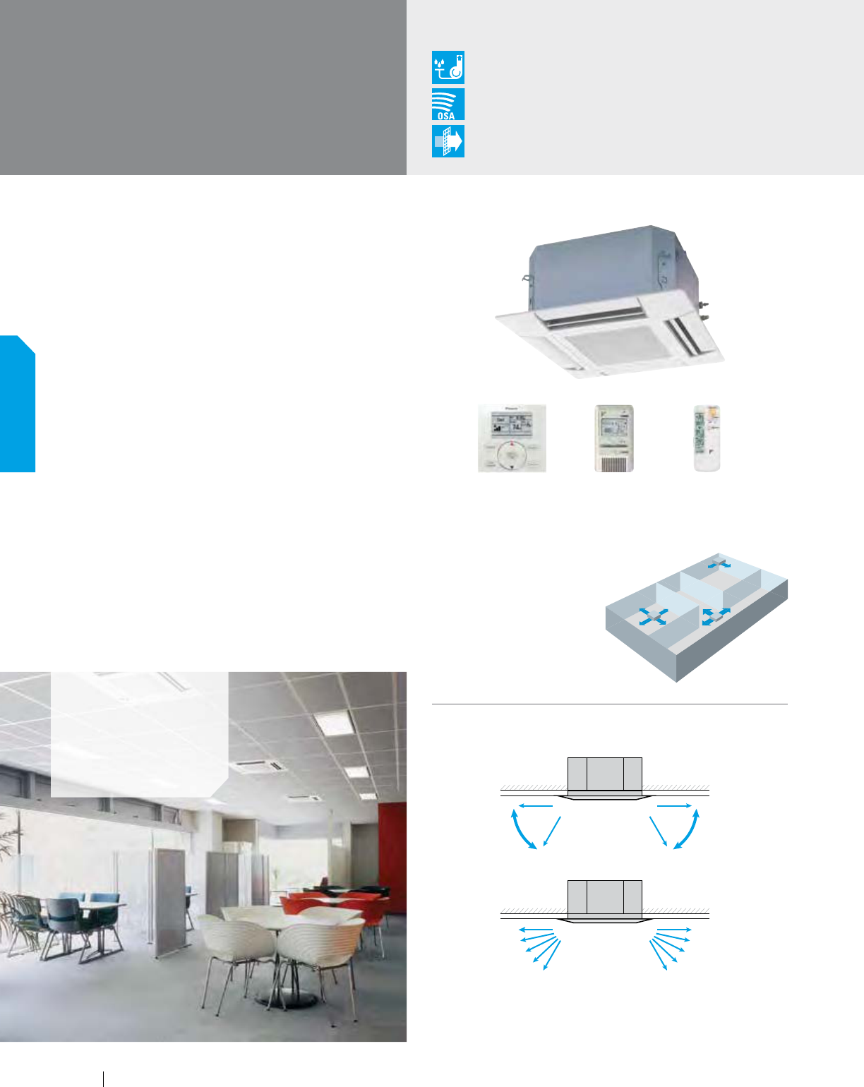
Elegant, Low-maintenance, Comfortable
The 2'x 2' 4-way Cassette is ideal for open plan applications
such as classrooms, offices and retail. It provides both low
noise and customizable comfort. Air can be distributed in any
of four directions and the 2'x 2' size of the unit makes layout and
installation very easy.
Features and Benefits
Fits in a standard 2'x 2' ceiling grid.
Sound pressure levels are as low as 29 dB(A)
Space-saving depth of units requires
only 11.6" of ceiling space
Three auto-swing positions to choose from — standard,
draft prevention and ceiling stain prevention
Simple installation with an easy-to-fit
decoration panel, easy height adjustment and
a suction grille that can rotate up to 90°
Easy-to-clean grille, washable long-life filter
Condensate pump inside the unit with
up to 21-1/2" lift as standard
Models range from 7.5 MBH to 18 MBH
FXZQ-MVJU9
2'x2' 4-Way
Ceiling-Mounted Cassette
Condensate Pump
as Standard
Outside Air
Integration Possible
Filter
Included
Applications
Retail
Schools
Offices
2-, 3-, and 4-way airflow patterns are available, enabling installation in the corner
of a room.
For 3-way or 2-way flow installation, the sealing member for air discharge outlet
(option) must be used to close each unused outlet.
Angles can be also set on site to prevent drafts (0°-35°) or soiling of the
ceiling (25°-60°), other than standard setting (0°-60°).
4-Way Flow 3-Way Flow
L-Shaped
2-Way Flow
Auto Swing: Wide discharge angle: 0° to 60°
0°
60°60°
0°
0°
60°60°
0°
Fixed Angles: 5 Levels
Airflow Angles
BRC2A71 (option) BRC7E830 (option)BRC1E73 (option)
Flexible Airflow Patterns
The four air louvers in the
unit enables comfortable
space environment in many
different room layouts.
62
INDOOR UNITS
www.daikincomfort.com
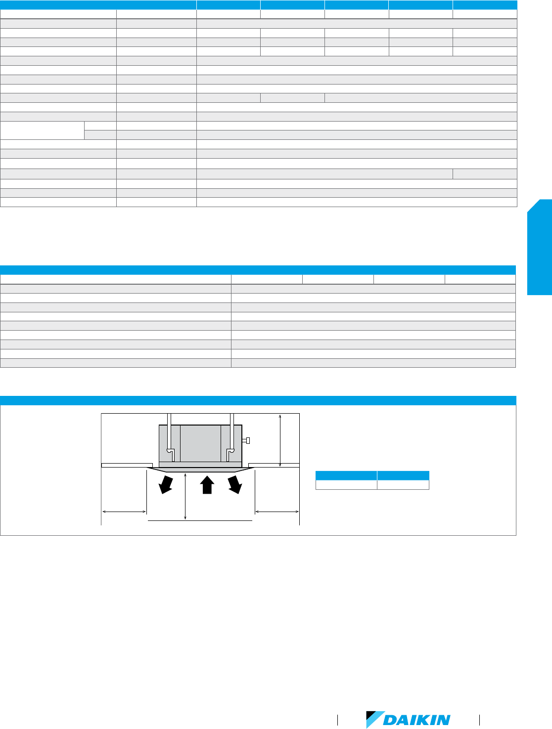
FXZQ-MVJU9 SPECIFICATIONS 0.6 TON 0.75 TON 1 TON 1.25 TON 1.5 TON
Model Name FXZQ07MVJU9 FXZQ09MVJU9 FXZQ12MVJU9 FXZQ15MVJU9 FXZQ18MVJU9
Power Supply V/ph/Hz 208-230/1/60
Rated Cooling Capacity BTU/h 7,500 9,500 12,000 15,000 18,000
Rated Heating Capacity BTU/h 8,700 11,100 14,000 17,500 21,000
Airflow Rate (H/L) CFM 320/247 335/265 335/265 388/282 495/353
Weight lbs 42
Height in. 11-1/4
Width in. 22-5/8
Depth in. 22-5/8
Sound Pressure (H/L) dB(A) 31/29 33/29 41/34
Condensate Pump Lift in. 21-1/2
Condensate Pipe Connection in. O.D. 1-1/32
Pipe Connections
Gas in. 1/2 (Flare)
Liquid in. 1/4 (Flare)
Refrigerant R-410A
Refrigerant Control Electronic Expansion Valve
Maximum Overcurrent Protective Device A 15
Minimum Circuit Amps A 0.8 0.9
Protection Devices Fuse and Fan Motor Thermal Protector
External Finish Galvanized Steel Plate
Standard Filter Type Resin Net (with Mold Resistant)
FXZQ-MVJU9 ACCESSORIES
Model Name FXZQ07MVJU9 FXZQ09MVJU9 FXZQ12MVJU9 FXZQ18MVJU9
Navigation Remote Controller
*
BRC1E73
Simplified Wired Remote Controller
*
BRC2A71
Remote Sensor Kit KRCS01-1B
Decoration Panel BYFQ60B8W1U
Wiring Adapter PCB (interface with aux/primary heater, humidifier, OA damper/fan) KRP1B72
Long-Life Replacement Filter KAFQ441BA60
Sealing Member of Air Discharge Outlet KDBHQ44B60
Panel Spacer KDBQ44B60
Fresh Air Intake Kit KDDQ44XA60
*
Optional face plates available to provide a more intuitive user interface and disable specific functions
FXZQ-MVJU9 INSTALLATION SPACE
*59" or
more
*59" or
more
H
Air
inlet
Air
discharge
Air
discharge
59" or more
* Leave 7-7/8" or more space on sides
where the air outlet is closed.
Nominal Conditions: Cooling Mode
Indoor: 80 °F DB / 67 °F WB
Outdoor: 95 °F DB
Pipe Length: 25 ft.
Level Difference: 0 ft.
H
eating Mode
Indoor: 70 °F DB
Outdoor: 47 °F DB / 43 °F WB
Pipe Length: 25 ft.
Level Difference: 0 ft.
No
te: Specifications are subject to change
without notice.
MODEL HEIGHT
FXZQ07-18MVJU9 11.6" or more
VRV Product Catalog
63
INDOOR UNITS
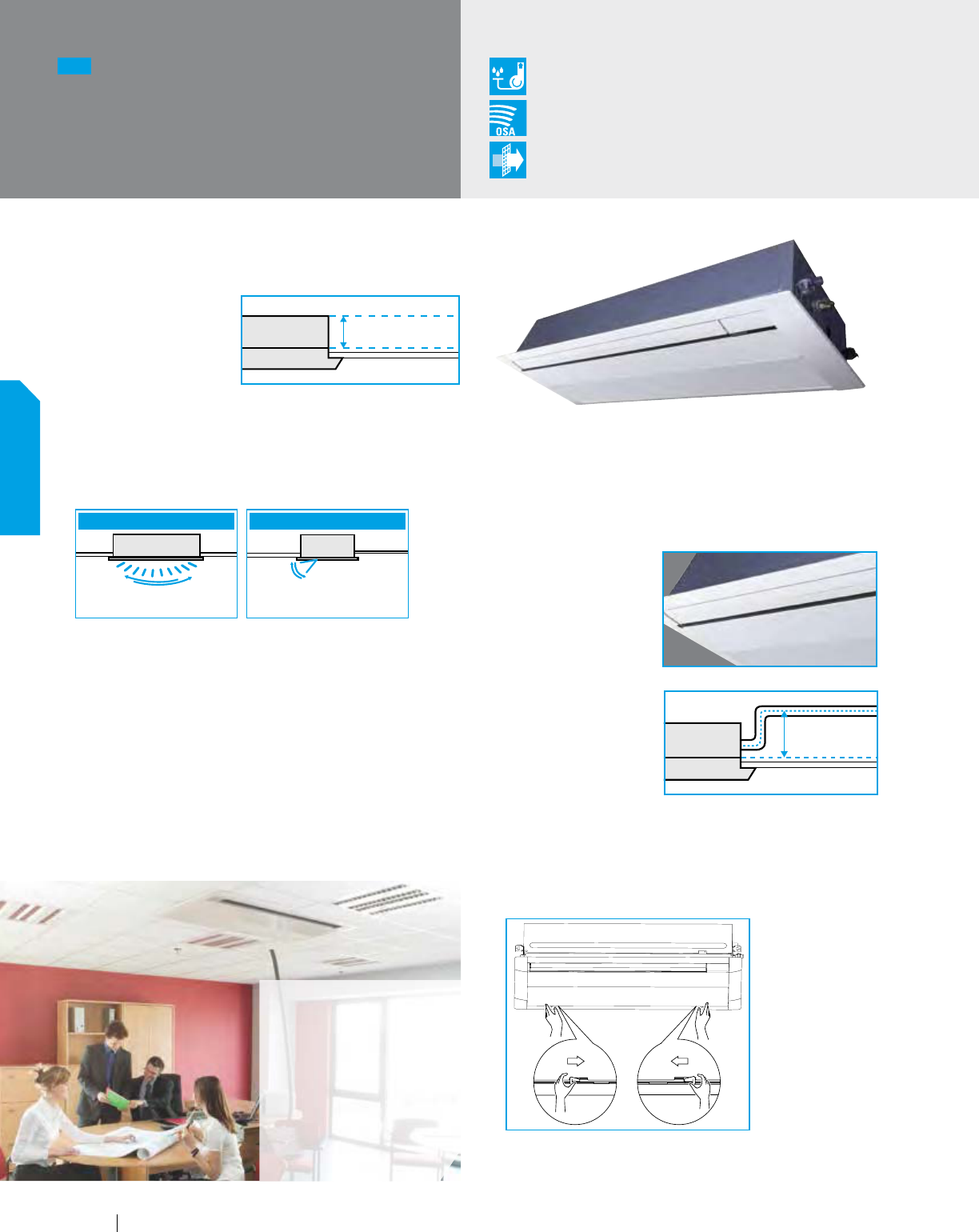
Slim and Compact Design for Installation Flexiblity
Features and Benefits
The main body of the
unit is optimized to be
a compact design.
Only 7-⅞" in height and
a width of 18-½" making it possible to use this style of indoor
unit in the tightest of spaces.
The innovative discharge air louver design forces air in
heating mode to ground level to improve the overall
space heating effect of the indoor unit.
The unit is equipped with both horizontal and vertical
louvers that can be freely adjusted with the remote
controller providing a capability to optimize the airflow
and throw to suit your room design.
The utilization of both a DC-style Fan Motor and integrated
Condensate Pump allow for improvements in energy
consumption as well as lower operating sound levels than
other styles of indoor units.
This Indoor unit can be set to 5 predetermined fan speeds
using the BRC1E73 wired remote controller, which allows
for optimum and comfortable airflow.
Condensate Pump
as Standard
Outside Air
Integration Possible
Filter
Included
Applications
Hotel Rooms
Offices
Residential
(Apartments,
Condominiums,
etc.)
A Ventilation Air knock-out is provided to allow up to
15% of the rated airflow through the unit to be pretreated
outside air.
The innovative “smooth finish” decoration panel design
helps to minimize dust and dirt build-up
and facilitates
easier cleaning.
The Indoor Unit is
equipped with a factory
installed condensate
pump with a lift
capacity of up to
33-7/16" (measured
from the bottom of
the unit).
The units are equipped
with customizable
auxiliary heat control
settings to facilitate the
On/Off control of an external auxiliary heat solution.
For ease of service and maintenance activities, it is
possible to access the main components of the unit
by only removing the decoration panel.
Overview of the vertical fins
to the right or left up to 45˚
Balance of horizontal fins to
frequent between 20˚ and 70˚
Front view Side view
7-⅞"
31-½"
NEW
FXEQ-PVJU
Ceiling-Mounted Cassette
(Single Flow)
64
INDOOR UNITS
www.daikincomfort.com
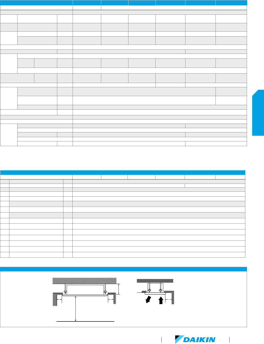
FXEQ-PVJU SPECIFICATIONS 0.6 TON 0.75 TON 1.0 TON 1.25 TON
1.5 TON 2 TON
MODEL
FXEQ07PVJU FXEQ09PVJU FXEQ12PVJU FXEQ15PVJU FXEQ18PVJU FXEQ24PVJU
Power Supply 1 phase 60Hz 208/230V
Cooling
capacity
*1,*3 Btu/h (kW) 7500 (2.5) 9500 (2.8) 12000 (3.5) 15000 (4.4) 18000 (5.3) 24000 (7.0)
Heating
capacity
*2,*3 Btu/h (kW) 8500 (2.5) 10500 (3.1) 13500 (4.0) 17000 (5.0) 20000 (5.9) 27000 (7.9)
Electrical
Min. circuit amps (MCA) A
0.3 0.4 0.4 0.5 0.5 0.7
Max. overcurrent
protection (MOP)
A
15 15 15 15 15 15
Casing/color Galvanized steel plate
Dimensions: (H x W x D) in. (mm)
7-⅞ x 18-½ x 33-1-1/16 (200 x 470 x 840) 7-⅞ x 18-½ x 48-13/16 (200 x 470 x 1240)
Fan
Type Sirocco fan
Air flow rate
(Dry coiI)
Cooling
(H/HM/M/ML/L)
CFM
(m
3
/min)
212/191/173/155/141
(6.0/5.4/4.9/4.4/4.0)
244/226/205/187/170
(6.9/6.4/5.8/5.3/4.8)
283/265/247/223/194
(8.0/7.5/7.0/6.3/5.5)
346/311/276/247/219
(9.8/8.8/7.8/7.0/6.2)
441/403/367/336/307
(12.5/11.4/10.4/9.5/8.7)
530/481/431/389/346
(15.0/13.6/12.2/11.0/9.8)
Drive Direct drive
Sound pressure level
Cooling
(H/HM/M/ML/L)
dBA 30/29/28/27/26 32/31/30/29/28 35/34/33/32/30 38/37/35/33/31 38/37/35/33/31 43/41/39/37/35
Weight lbs (kg) 37.5 (17) 39.7 (18) 50.7 (23)
Piping
connections
Liquid in. (mm)
ø ¼ (6.4) (flare connection) ø ⅜ (9.5)
(fIare connection)
Gas in. (mm)
ø ½ (12. 7) (flare connection)
ø ⅝ (15.9)
(flare connection)
Drain in. (mm) PVC26 (0.D. 1-1/32 (26) x I.D. 13/16 (20))
Drain pump Iift in. (mm)
25 (635)
Refrigerant control Electronic expansion valve
Connectable outdoor unit R-410A VRV Series
Decoration
paneI
(required
o
ption)
Model BYEP40AW1 BYEP63AW1
Color Fresh White
Dimensions (H x W x D) in. (mm)
3-3/16 x 21-
⅝ x 37-13/32 (80 x 550 x 950) 3-3/16 x 21-⅝ x 53-5/32 (80 x 550 x 1350)
Air filter Resin net (with mold resistant)
Weight Ibs (kg) 17.6 (8) 22 (10)
Note:
*
1. Nominal cooling capacities are based on the following conditions: return air temperature: 80.0˚ FDB (26.7˚C DB), 67.0˚ FWB (19.4˚CWB), outdoor temperature: 95.0˚ FDB (35.˚C DB)
equivalent ref. piping: 25ft. (7.6m) (Horizontal)
*
2. Nominal heating capacities are based on the following conditions: return air temperature: 70.0˚ FDB (21.1˚C DB), outdoor temperature: 47.0˚ FDB (8.3˚C DB), 43.0˚ FDB (6.1˚C WB)
equivalent ref. piping: 25ft. (7.6m) (Horizontal)
*
3 Capacities are net, including a deduction for cooling (an addition for heating) for indoor fan motor heat.
FXEQ-PVJU ACCESSORIES
MODEL
FXEQ07PVJU FXEQ09PVJU FXEQ12PVJU FXEQ15PVJU FXEQ18PVJU FXEQ24PVJU
No. Name of Option Note
1 Decoration panel
BYEP40AW1 BYEP63AW1
2 Wired remote controller BRC1E73
3 Simplified remote controller
BRC2A71
4 Remote sensor KRCS01-4B
5 Central remote controller DCS302C71
5-1 Electrical box 1 KJB311A A
6 Unified on/off controller DCS301C71
6-1 Electrical box 1 KJB212AA
7 Schedule timer DST301BA61
8 intelligent Touch controller DCS601C71
9 DIII-NET expander adaptor DTA109A51
10 Wiring adaptor printed circuit board 2 KRP1C75
11 Group control adaptor printed circuit board 2 KRP4A74
12 Adaptor mounting box KRP1B101
Note:
*
1. Electrical box (No.5-1/6-1) is required for controlIer (No. 5/6)
*
2. Adaptor mounting box (No.12) is necessary.
FXEQ-PVJU INSTALLATION SPACE
More than 6 (150)
More than 6 (150)
More than 6 (150)
Air outlet
Figure 2
Figure 1
[Ceiling]
Unit: [in. (mm)]
More than 10-15/64 (260)
More than 40(1000)
VRV Product Catalog
65
INDOOR UNITS
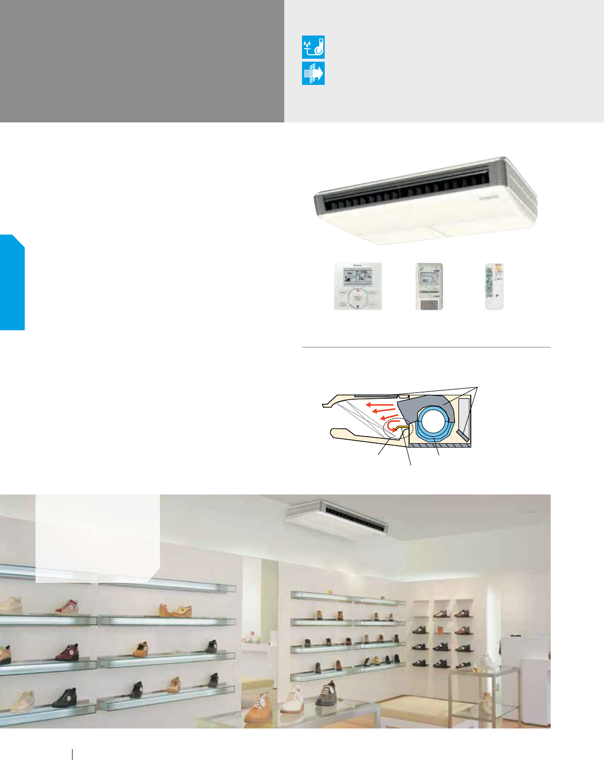
Slim, Efficient, Quiet, Easy to Maintain
With its slim, elegant design, the FXHQ ceiling-suspended
unit is a great fit for any light commercial space. Wide air
openings provide a comfortable airflow and an innovative stream
fan ensures quiet operation, making it ideal for retail stores,
restaurants, classrooms and conference rooms.
Features and Benefits
One of our slimmest indoor units (less than
8") fits within any interior design
Wide air discharge outlet distributes a comfortable airflow
throughout the entire space with throw of up to 25 ft.
Innovative stream fan technology keeps
sound pressure levels low
Smooth flat louver design makes cleaning simple
Long-life filter is standard
Models range from 12 MBH to 36 MBH
FXHQ-MVJU
Ceiling-Suspended Unit
Applications
Retail/shops
Offices
Restaurants
Uses the quiet stream fan and many more advanced technologies.
Sound absorption
member
Turbulent flow
is produced
Straightening vane
Quiet stream fan
Quiet Stream Fan (side view)
BRC2A71 (option) BRC7E83 (option)BRC1E73 (option)
Optional
Condensate Pump
Filter
Included
66
INDOOR UNITS
www.daikincomfort.com
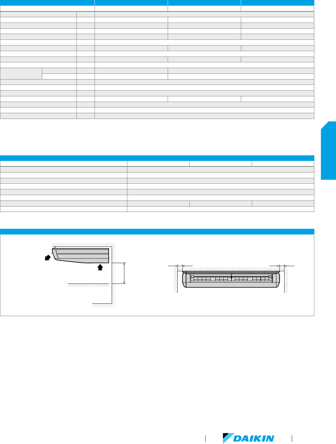
FXHQ-MVJU SPECIFICATIONS 1 TON 2 TON 3 TON
Model Name FXHQ12MVJU FXHQ24MVJU FXHQ36MVJU
Power Supply V/ph/Hz 208-230/1/60
Rated Cooling Capacity BTU/h 12,000 24,000 36,000
Rated Heating Capacity BTU/h 13,500 27,000 40,000
Airflow Rate (H/L) CFM 410/340 710/600 830/670
Weight lbs 55 80 90
Height in. 7-11/16
Width in. 37-13/16 55-1/8 62-5/8
Depth in. 26-3/4
Sound Pressure (H/L) dB(A) 42/33 44/36 46/41
Condensate Pipe Connection in. O.D. 1
Pipe Connections
Gas in. 1/2 (Flare) 5/8 (Flare)
Liquid in. 1/4 (Flare) 3/8 (Flare)
Refrigerant R-410A
Refrigerant Control Electronic Expansion Valve
Maximum Overcurrent Protective Device A 15
Minimum Circuit Amps A 0.8 1.0 1.4
Protection Devices Fuse and Fan Motor Thermal Protector
External Finish White Casing
Standard Filter Type Resin Net (with Mold Resistant)
FXHQ-MVJU ACCESSORIES
Model Name FXHQ12MVJU FXHQ24MVJU FXHQ36MVJU
Navigation Remote Controller
*
BRC1E73
Simplified Wired Remote Controller
*
BRC2A71
Wireless Remote Controller BRC7E83
Remote Sensor Kit KRCS01-1B
Wiring Adapter PCB (interface with aux/primary heater, humidifier, OA damper/fan) KRP1C74
Group Control Adapter PCB (connects to external BMS) KRP4A72
Replacement long-life filter KAFJ501D56 K AFJ501D112 KAFJ501D160
Condensate Pump DACA-CP3-1
*
Optional face plates available to provide a more intuitive user interface and disable specific functions
FXHQ-MVJU INSTALLATION SPACE
Air outlet
Air inlet
12" or more
Obstruction
Requ
ired service space
Floor
1-3/16" or more 1-3/16" or more
Nominal Conditions: Cooling Mode
Indoor: 80 °F DB / 67 °F WB
Outdoor: 95 °F DB
Pipe Length: 25 ft.
Level Difference: 0 ft.
H
eating Mode
Indoor: 70 °F DB
Outdoor: 47 °F DB / 43 °F WB
Pipe Length: 25 ft.
Level Difference: 0 ft.
No
te: Specifications are subject to change
without notice.
VRV Product Catalog
67
INDOOR UNITS
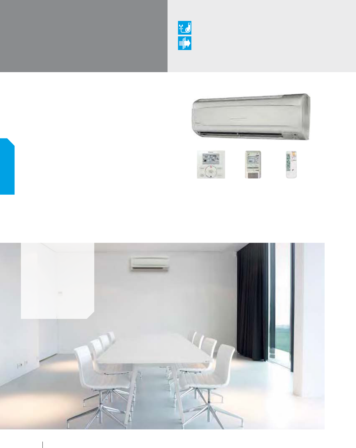
Stylish, Compact, Convenient, Comfortable
Daikin's wall-mounted units are ideal for cooling or heating
smaller zones such as stores, offices, and restaurants. The
compact, stylish design lets the unit blend discreetly into any
interior design, and airflow can be supplied in any of five different
directions and easily programmed via remote control.
Features and Benefits
Auto-swing mechanism ensures efficient air distribution via
louvers that automatically close when the unit is turned off
Wide air discharge outlet distributes a comfortable
airflow throughout the entire space
Horizontal louvers and front panel can
be easily removed for cleaning
Drain pipe can be easily hidden from sight
Models range from 7.5 MBH to 24 MBH
FXAQ-PVJU
Wall-Mounted Unit
Applications
Retail
Restaurants
Offices
Hotels
Multi-family
residences
BRC2A71 (option) BRC7E818 (option)BRC1E73 (option)
Optional
Condensate Pump
Filter
Included
68
INDOOR UNITS
www.daikincomfort.com
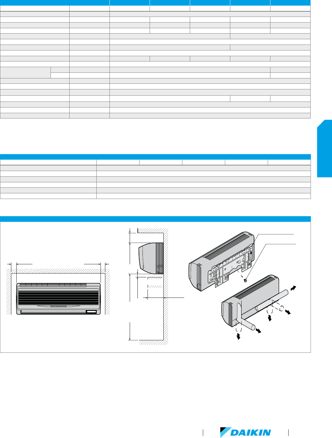
FXAQ-PVJU SPECIFICATIONS 0.6 TON 0.75 TON 1 TON 1.5 TON 2 TON
Model Name FXAQ07PVJU FXAQ09PVJU FXAQ12PVJU FXAQ18PVJU FXAQ24PVJU
Power Supply V/ph/Hz 208-230/1/60
Rated Cooling Capacity BTU/h 7,500 9,500 12,000 18,000 24,000
Rated Heating Capacity BTU/h 8,500 10,500 13,500 20,000 27,000
Airflow Rate (H/L) CFM 260/160 280/175 300/180 500/400 635/470
Weight lbs 25 31
Height in. 11-3/8
Width in. 31-1/4 41-3/8
Depth in. 9
Sound Pressure (H/L) dB(A) 36/31 37/ 31 38/31 43/37 47/40
Condensate Pipe Connection in. O.D. 11/16
Pipe Connections
Gas in. 1/2 (Flare) 5/8 (Flare)
Liquid in. 1/4 (Flare) 3/8 (Flare)
Refrigerant R-410A
Refrigerant Control Electronic Expansion Valve
Maximum Overcurrent Protective Device A 15
Minimum Circuit Amps A 0.4 0.5 0.6
Protection Devices Fuse and Fan Motor Thermal Protector
External Finish White Casing
Standard Filter Type Resin Net (washable)
FXAQ-PVJU ACCESSORIES
Model Name FXAQ07PVJU FXAQ09PVJU FXAQ12PVJU FXAQ18PVJU FXAQ24PVJU
Navigation Remote Controller
*
BRC1E73
Simplified Wired Remote Controller
*
BRC2A71
Wireless Remote Controller BRC7E818
Remote Sensor Kit KRCS01-1B
Group Control Adapter PCB (Connects to external BMS) KRP4A71
Condensate Pump DACA-CP1-1
*
Optional face plates available to provide a more intuitive user interface and disable specific functions
FXAQ-PVJU INSTALLATION SPACE
Fig.1
≥ 2" ≥ 2"
Fig.2
≥ 3-1/2"
≥ 1-1/4"
Floor
Obstruction
≤ 4-3/4"
≥ 100" (from floor)
For installation
in high places.
Installation panel (1)
Temporary screw
(In case of 12 type)
Left pi
pe
Back-left pipe
Back-right pipe
Bottom-left pipe
Bottom-right pipe
Fig.3
Nominal Conditions: Cooling Mode
Indoor: 80 °F DB / 67 °F WB
Outdoor: 95 °F DB
Pipe Length: 25 ft.
Level Difference: 0 ft.
H
eating Mode
Indoor: 70 °F DB
Outdoor: 47 °F DB / 43 °F WB
Pipe Length: 25 ft.
Level Difference: 0 ft.
No
te: Specifications are subject to change
without notice.
VRV Product Catalog
69
INDOOR UNITS
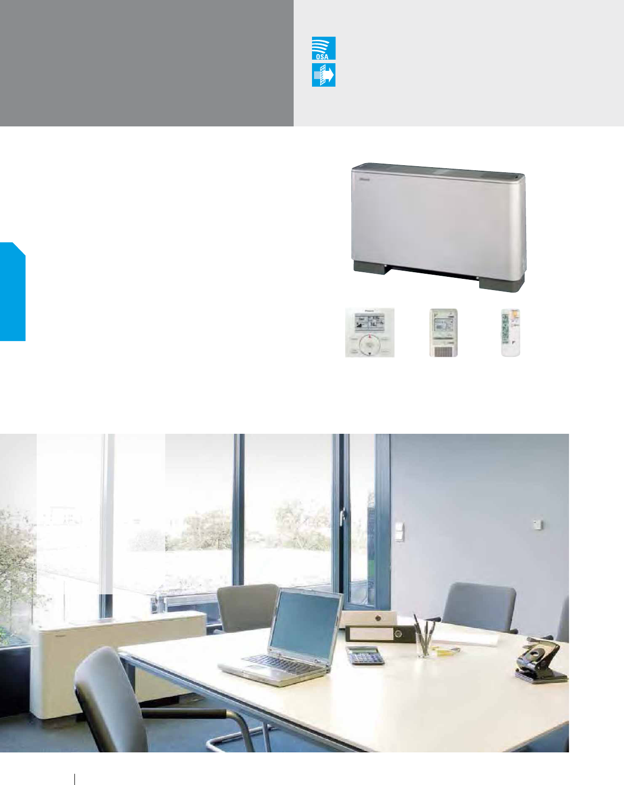
Versatile, Logical, Durable, Quiet
The ideal way to save space, our floor-standing units can easily
be installed along a perimeter wall. The air distribution from these
models will allow you to find the right balance for classrooms,
churches, office hallways or similar spaces.
Features and Benefits
Ideal for installation beneath a window
Unit requires minimal installation space
Fitted with a washable long-life filter
Remote-control options available
Space-saving unit can be freestanding or wall-mounted
Models range from 7.5 MBH to 24 MBH
FXLQ-MVJU9
Floor-Standing Unit
Outside Air
Integration Possible
Filter
Included
Applications
Multi-family
residences
Single-family
residences
Churches
Historic buildings
Schools
Offices
BRC2A71 (option) BRC4C82 (option)BRC1E73 (option)
70
INDOOR UNITS
www.daikincomfort.com
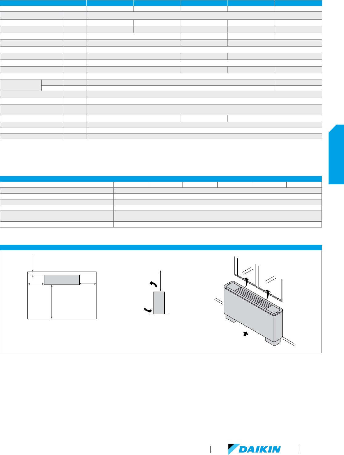
FXLQ-MVJU9 SPECIFICATIONS 0.6 TON 0.75 TON 1 TON 1.5 TON 2 TON
Model Name FXLQ07MVJU9 FXLQ09MVJU9 FXLQ12MVJU9 FXLQ18MVJU9 FXLQ24MVJU9
Power Supply V/ph/Hz 208-230/1/60
Rated Cooling Capacity BTU/h 7,500 9,500 12,000 18,000 24,000
Rated Heating Capacity BTU/h 8,500 10,500 13,500 20,000 27,000
Airflow Rate (H/L) CFM 245/210 280/210 490/380 560/420
Weight lbs 58 66 80
Height in. 23-5/8
Width in. 39-3/8 44 -7/8 55 -7/8
Depth in. 8-3/4
Sound Pressure (H/L) dB(A) 35/32 36/33 40/35 41/36
Condensate Pipe Connection in. O.D. 27/32
Pipe Connections
Gas in. 1/2 (Flare) 5/8 (Flare)
Liquid in. 1/4 (Flare) 3/8 (Flare)
Refrigerant R-410A
Refrigerant Control Electronic Expansion Valve
Maximum Overcurrent
Protective Device
A 15
Minimum Circuit Amps A 0.3 0.5 0.6
Protection Devices Fuse and Fan Motor Thermal Protector
External Finish Ivory White Casing
Standard Filter Type Resin Net (with Mold Resistant)
FXLQ-MVJU9 ACCESSORIES
Model Name FXLQ12MVJU9 FXLQ18MVJU9 FXLQ24MVJU9 FXNQ12MVJU9 FXNQ18MVJU9 FXNQ24MVJU9
Navigation Remote Controller
*
BRC1E73
Simplified Wired Remote Controller
*
BRC2A71
Wireless Remote Controller BRC4C82
Remote Sensor Kit KRCS01-1B
Wiring Adapter PCB (interface with aux/primary heater,
humidifier, OA damper/fan)
KRP1C74
Group Control Adapter PCB (connects to external BMS) KRP4A71
*
Optional face plates available to provide a more intuitive user interface and disable specific functions
FXLQ-MVJU9 INSTALLATION SPACE
Base
4" or more4" or more
3/4" or
more
40" or more
70" or more
Air flow
direction
Air inlet
direction
Front
side
Window
Nominal Conditions: Cooling Mode
Indoor: 80 °F DB / 67 °F WB
Outdoor: 95 °F DB
Pipe Length: 25 ft.
Level Difference: 0 ft.
H
eating Mode
Indoor: 70 °F DB
Outdoor: 47 °F DB / 43 °F WB
Pipe Length: 25 ft.
Level Difference: 0 ft.
No
te: Specifications are subject to change
without notice.
VRV Product Catalog
71
INDOOR UNITS

www.daikincomfort.com72

VRV Product Catalog
73
Outdoor Units
Outdoor Units
1
Maximum 34 tons for Heat Pump
2
Complete warranty details available from your local distributor or manufacturer's representative or at www.daikincomfort.com.
Air-Cooled Condensers
Heat Pump & Heat Recovery
6 to 38
1
Tons 208-230V/60Hz/3ph or 460V/60Hz/3ph
Daikin's VRV IV systems integrate
advanced technology to provide comfort
control to help maximize energy efficiency
and reliability. Currently available in heat
pump and heat recovery configurations,
VRV IV provides a solution for multi-family
residential to large commercial applications
desiring heating or cooling. VRV IV is
optimized for low total Life Cycle Cost
(LCC) with larger capacity single modules (now range up to
14 Tons), improved seasonal efficiency, as compared to VRV
III, with automatic and customizable Variable Refrigerant
Temperature (VRT) climate tuning and outstanding warranty
2
with 10 year compressor and parts limited warranty as standard.
The VRV IV is the first variable refrigerant flow (VRF) system to
be assembled in North America.
Heat Recovery
6 to 12 Tons 208-230V/60Hz/3ph or 6 to 10 Tons 480V/60Hz/3ph
Advanced continuous heating during defrost cycle and oil return
for single module systems
Variable Refrigerant Temperature
(VRT) control
Extended operating range with
heating function down to -4°F
ambient air temperature
Air-Cooled Condensers,
1 Phase Power Supply
Heat Pump
3 and 4 Tons 208-230V/60Hz/1ph
Ideal for residential and light commercial
applications, VRV III-S air cooled systems are
available in 3 and 4 tons and can operate up to 8
fan coil units. These systems provide individual
zone control and advanced zoning capabilities in
an innovative space saving design.
NEW
Water-Cooled Condensers
Heat Pump or Heat Recovery
6 to 21 Tons 208-230V/60Hz/3ph or 460V/60Hz/3ph
Great for both light and large commercial
applications, the VRV IV W-Series
provides cold climate capabilities
in a lightweight, compact design.
Available as a unified heat pump or heat
recovery solution, the VRV IV W-Series
offers an energy-saving alternative to
centralized systems.
an innovative space saving design.
Advanced continuous heating during defrost cycle and oil return
www.daikincomfort.com74
OUTDOOR UNITS
Local assembly of products
enables Daikin to react fast to
changes in the marketplace and
truly optimize the product for the
North American market.
VRV Product Catalog
75
OUTDOOR UNITS
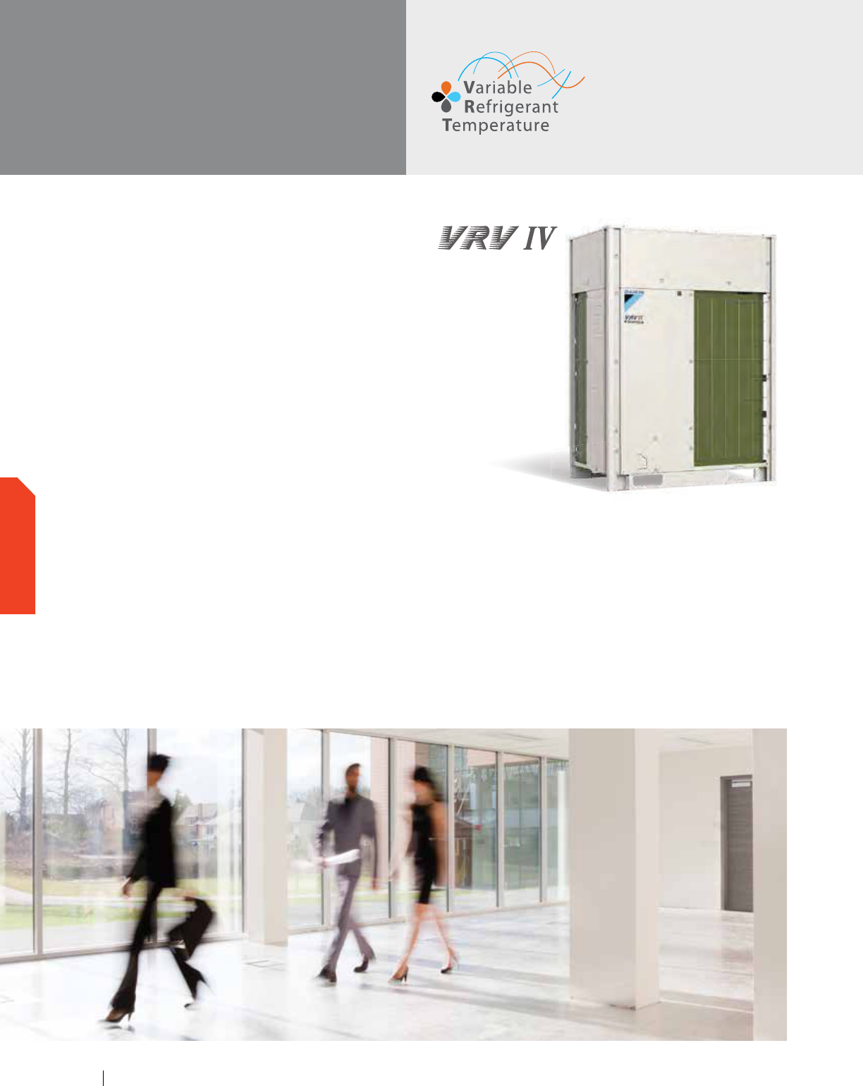
Daikin’s VRV IV systems integrate advanced technology to
provide comfort control to help maximize energy efficiency and
reliability. VRV IV provides a heating and cooling solution for
multi-family residential to large commercial applications. Daikin
VRV IV is the first variable refrigerant flow (VRF) system to be
assembled in North America.
Features and Benefits
Total comfort solution for heating, cooling, ventilation
and controls
All inverter compressors and inverter fan motors optimize part
load efficiency.
Redesigned and optimized for low total Life Cycle Cost (LCC)
New single/multiple port branch selector boxes provide
compact dimensions and a wide range of product offerings
(single, 4, 6, 8, 10 and 12 port options)
Reduced install cost and increased flexibility as compared to
VRV III with larger capacity single modules up to 14 Tons and
system capacity up to 38 Tons
Efficiency improved over VRV III by an average of 21% with
IEER Values now up to 29.3
Improved seasonal efficiency as compared to VRV III with
automatic and customizable Variable Refrigerant Temperature
(VRT) climate tuning
Outstanding warranty
*
with 10 year compressor and parts
limited warranty as standard
Reduced commissioning time vs. VRV III with VRV configurator
software and Graphical User Interface (GUI)
Design flexibility with long piping lengths up to 3,280 ft. total
and up to 100 ft. vertical separation between indoor units
Take advantage of Daikin’s unique zone and centralized controls
that are optimized for the specific needs of North America
*
Complete warranty details available from your local distributor
or manufacturer’s representative or at www.daikincomfort.com.
VRV IV
Air-Cooled
Heat Recovery
www.daikincomfort.com76
OUTDOOR UNITS
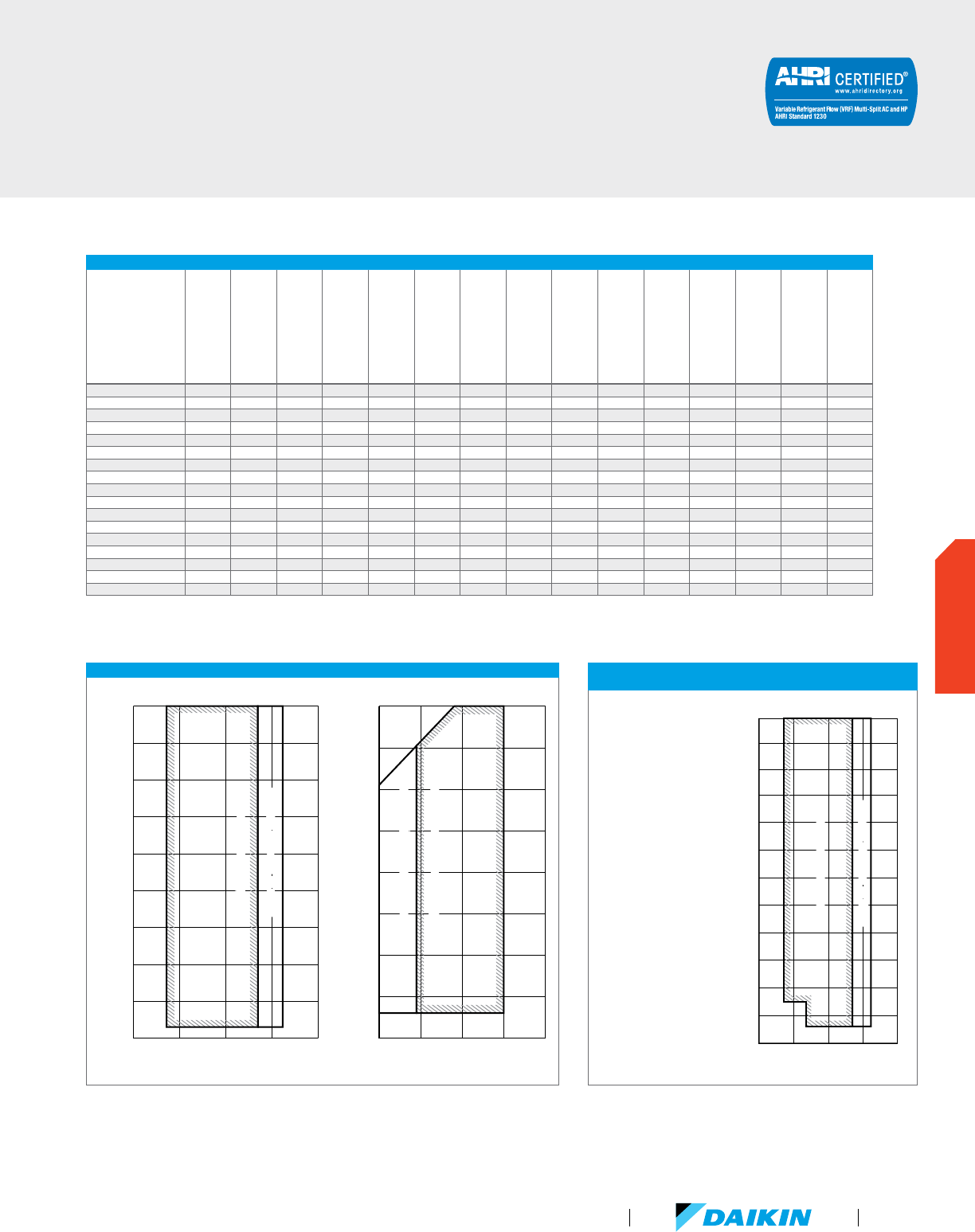
VRV IV CERTIFIED DATA - HEAT RECOVERY, 208-230V/60HZ/3PH AND 460V/60HZ/3PH
Product #
IEER Non-Ducted
IEER Ducted
IEER Mixed
SCHE Non-Ducted
SCHE Ducted
SCHE Mixed
COP @ 47°F Non-Ducted
COP @ 47°F Ducted
COP @ 47°F Mixed
COP @ 17°F Non-Ducted
COP @ 17°F Ducted
COP @ 17°F Mixed
EER Non-Ducted
EER Ducted
EER Mixed
REYQ72T 26.20 20.80 23.50 27.80 22.60 25.20 4.29 3.82 4.06 2.77 2.63 2.70 15.80 13.40 14.60
REYQ96T 29.30 21.00 25.15 27.30 23.00 25.15 4.25 3.72 3.99 2.63 2.31 2.47 15.10 13.10 14.10
REYQ120T 25.40 20.70 23.05 27.90 25.10 26.50 3.98 3.51 3.75 2.54 2.32 2.43 13.90 12.60 13.25
REYQ144T 24.20 20.70 22.45 25.50 23.80 24.65 3.81 3.55 3.68 2.56 2.35 2.46 12.90 11.90 12.40
REYQ168T 22.00 19.50 20.75 26.60 22.80 24.70 3.77 3.33 3.55 2.32 2.15 2.24 11.70 11.30 11.50
REYQ192T 22.90 20.40 21.65 26.60 22.90 24.75 3.84 3.67 3.76 2.55 2.38 2.47 12.50 12.60 12.55
REYQ216T 22.90 20.20 21.55 25.60 22.50 24.05 3.73 3.67 3.70 2.45 2.28 2.37 12.50 12.40 12.45
REYQ240T 21.90 19.20 20.55 25.60 22.70 24.15 3.67 3.55 3.61 2.48 2.31 2.40 12.20 11.60 11.90
REYQ264T 21.60 18.10 19.85 24.40 22.00 23.20 3.55 3.38 3.47 2.42 2.26 2.34 11.80 10.50 11.15
REYQ288T 21.40 18.20 19.80 23.30 21.40 22.35 3.51 3.26 3.39 2.41 2.24 2.33 11.80 10.90 11.35
REYQ312T 20.20 17.8 0 19.00 23.60 20.30 21.95 3.56 3.22 3.39 2.41 2.24 2.33 11.30 10.60 10.95
REYQ336T 19.00 17.00 18.00 23.20 20.40 21.80 3.52 3.20 3.36 2.18 2.06 2.12 10.70 10.00 10.35
REYQ360T 19.60 17.90 18.75 22.60 20.20 21.40 3.51 3.31 3.41 2.42 2.17 2.30 10.80 11.00 10.90
REYQ384T 18.30 16.60 17.45 22.40 18.70 20.55 3.21 3.21 3.21 2.34 2.06 2.20 9.80 9.80 9.80
REYQ408T 17.20 16.50 16.85 21.80 18.30 20.05 3.21 3.20 3.21 2.09 2.06 2.08 9.80 9.70 9.75
REYQ432T 16.20 16.50 16.35 21.10 18.10 19.60 3.21 3.20 3.21 2.08 2.06 2.07 9.80 9.70 9.75
REYQ456T 16.20 15.90 16.05 20.90 17.9 0 19.40 3.21 3.20 3.21 2.07 2.05 2.06 9.50 9.50 9.50
Certified efficiency data in accordance with ANSI/AHRI Standard 1230 2010, “Performance Rating of Variable Refrigerant Flow (VRF) Multi-Split Air Conditioning and Heat Pump Equipment” for the VRV
Series. The VRV IV Series has been designed and optimized to meet or exceed the latest minimum efficiency requirements in 10 C.F.R. Part 431 as determined by the U.S. Department of Energy (DOE) and
baseline efficiencies as defined by ASHRAE 90.1 2010. Systems under 65MBH are currently certified to AHRI 210/240. IEER ratings are as defined in ASHRAE 90.1 2010.
TECHNICAL COOLING FEATURE FOR VRV IV REYQ-T
HEAT RECOVERY OUTDOOR UNITS
Technical Cooling - Cooling
operation extended from
23°F ambient air temperature
down to -4°F
The Technical Cooling feature
is engaged by field settings on
the outdoor unit and on branch
selector boxes. It requires
addition of wind covers to
the unit and allows operation
down to -4° FDB ambient
temperature in cooling mode.
See the Engineering Data book
for complete application rules
and contact your local Daikin
representative for wind cover
specification requirements.
DETAILED OPERATION RANGES FOR VRV IV REYQ-T HEAT RECOVERY OUTDOOR UNITS
50 60 70 80 90
Indoor temperature (˚F WB)
110
100
90
Cooling
Outdoor temperature (˚F DB)
20
80
70
60
50
40
30
Range for pull-down operationRange for pull-down operation
Range for continuous operation
Range for continuous operation
50 60 70 80
90
Indoor temperature (˚F DB)
60
50
Heating
Outdoor temperature (˚F WB)
-20
40
30
20
10
0
-10
Range for continuous operation Range for continuous operation
Range for warming up operation
Range for warming up operation
60 70 80
Indoor temperature (˚F WB)
110
100
90
Ambient temperature (˚F DB)
20
10
0
-10
80
70
60
50
40
30
Range for pull-down operationRange for pull-down operation
Range for continuous operation
Range for continuous operation
Cooling
VRV Product Catalog
77
OUTDOOR UNITS
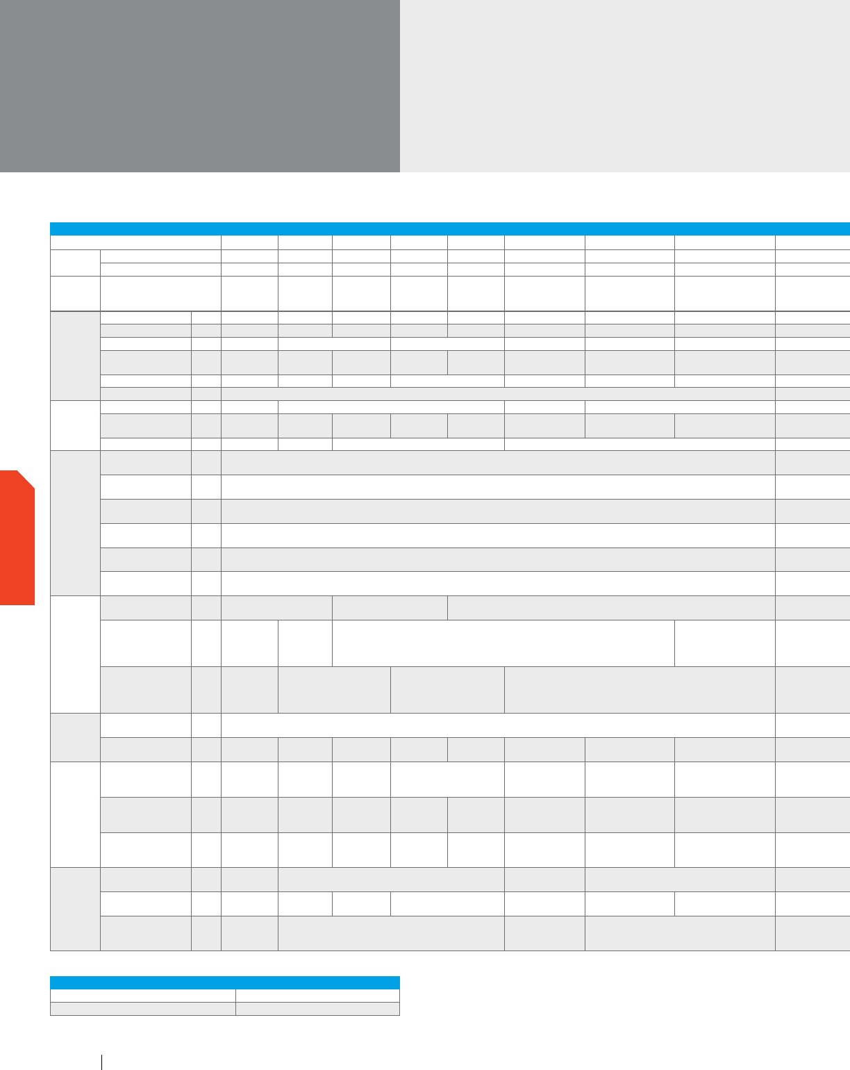
TECHNICAL DATA FOR VRV IV REYQ-TTJU/TYDN HEAT RECOVERY OUTDOOR UNITS
6 Ton 8 Ton 10 Ton 12 Ton
14 Ton
16 Ton 18 Ton 20 Ton 2 2 Ton 24 Ton 26 Ton 28 Ton 30 Ton 32 Ton 34 Ton 36 Ton 38 Ton
Model
208-230V/3Ph/60Hz REYQ72TTJU
REYQ96TTJU REYQ120TTJU REYQ144TTJU REYQ168T TJU
REYQ192TTJU REYQ216TTJU REYQ240TTJU REYQ264TTJU
REYQ288TTJU
REYQ312TTJU
REYQ336TTJU
REYQ360TTJU REYQ384T TJU REYQ408TTJU REYQ432TTJU REYQ456TTJU
460V/3Ph/60Hz
REYQ72TYDN
REYQ96TYDN
REYQ120TYDN
REYQ144TYDN REYQ168TYDN
REYQ192TYDN REYQ216TYDN REYQ240TYDN REYQ264TYDN
REYQ288TYDN
REYQ312TYDN
REYQ336TYDN
REYQ360TYDN REYQ384TYDN REYQ408TYDN REYQ432TYDN REYQ456TYDN
Combination
1 x REYQ120T
1 x REYQ72T
1 x R
EYQ120T
1 x REYQ96T
1 x REYQ144T
1 x REYQ96T
1 x REYQ144T
1 x REYQ120T
2 x REYQ144T
1 x REYQ168T
1 x REYQ144T
2 x REYQ168T 3 x REYQ120T
1 x REYQ168T
1 x REYQ120T
1 x REYQ96T
1 x R
EYQ168T
1 x REYQ144T
1 x REYQ96T
3 x REYQ144T
1 x REYQ168T
2 x REYQ144T
Performance
Rated Cooling Capacity BTU/h 67,000 90,000 111,000 134,000 156,000 180,000 200,000 222,000
246,000 268,000 290,000 312,000 334,000 356,000 380,000 400,000 415,000
Rated Heating Capacity BTU/h 75,000 100,000 126,000 150,000 176,000 200,000 226,000 250,000 276,000 300,000 326,000 352,000 376,000 415,000 415,000 425,000 435,000
Sound Pressure dB(A) 58 61 65 63 64 66 66 68 66 68 69 70
IEER (Ducted /
Non-Ducted)
20.8 / 26.2 21.0 / 29.3 20.7 / 25.4 20.7 / 24.2 19.5 / 22.0 20.4 / 22.9 20.2 / 22.9 19.2 / 21.9
18.1 / 21.6 18.2 / 21.4 17.8 / 20.2 17.0 / 19.0 17.9 / 19.6 16.6 / 18.3 16.5 / 17.2 16.5 / 16.2 15.9 / 16.2
Airflow CFM 5,544 5,827 6,286 8,228 5,544 + 6,286 5,827 + 6,286 5,827 + 8,228 6,286 + 8,228 8,228 + 8,228 8,228 + 8,228 6,286 + 6,286 + 6,286 5,827 + 6,286 + 8,228 5,827 + 8,228 + 8,228 8,228 + 8,228 + 8,228
Fan ESP, Standard/Max in. WG 0.12 / 0.32 0.12/0.32
Compressor
Compressors, all inverter Qty 1 2 3 4
4 6
Revolutions per minute RPM 3600 3630, 3630 4470, 4470 4440, 4440 5190, 5190 4080, (4290, 4290) (4170, 4170) x 2 (4050, 4050), (4110, 4110)
(4710, 4710),
(4800, 4800)
(4740, 4740)
x 2
(5190, 5190) x 2 (5010, 5010) x 3 (5070, 5070) x 2, (5160, 5160)
(5040, 5040),
(5130, 5130) x 2
(5220, 5220) x 3 (5730, 5730) x 3
Capacity Control Range % 15-100 11-100 10-100 5-100 5-100 3-100
Refrigerant
Piping,
Layout
Maximum Vertical Pipe
Length Above Unit
ft. 164 (295 With Field Setting)
164 (295 With Field Setting)
Maximum Vertical Pipe
Length Below Unit
ft. 131 (195 With Field Setting)
131 (195 With Field Setting)
Maximum Vertical Pipe
Length Between IDU
ft. 100
100
Maximum Actual
Pipe Length
ft. 541
541
Maximum Equivalent
Pipe Length
ft. 620
620
Maximum Total Pipe
Length
ft. 3,282
3,282
Refrigerant
Piping,
Connections
Liquid Pipe, Main Line in.
Φ3/8 (9.5) C1220T
(Brazing Connection)
Φ1/2 (12.7) C1220T
(Brazing Connection)
Φ5/8 (15.9) C1220T (Brazing Connection)
Φ3/4 (19.1) C1220T (Brazing Connection)
Suction Gas Pipe,
Main Line
in.
Φ3/4 (19.1)
C1220T
(Brazing
Connection)
Φ7/8 (22.2)
C1220T
(Brazing
Connection)
Φ1-1/8 (28.6) C1220T (Brazing Connection)
Φ1-3/8 (34.9) C1220T
(Brazing Connection)
Φ1-3/8 (34.9) C1220T (Brazing Connection) Φ1-5/8 (41.3) C1220T (Brazing Connection)
Discharge Gas Pipe,
Main Line
in.
Φ5/8 (15.9)
C1220T
(Brazing
Connection)
Φ3/4 (19.1) C1220T
(Brazing Connection)
Φ7/8 (22.2) C1220T
(Brazing Connection)
Φ1-1/8 (28.6) C1220T (Brazing Connection)
Φ1-1/8 (28.6) C1220T (Brazing Connection) Φ1-3/8 (34.9) C1220T (Brazing Connection)
Connection
Ratio
Standard Connectable
Indoor Unit Ratio
% 50 - 200
50 - 200
Maximum Number of
Indoor Units
Qty 12 16 20 25 29 33 37 41
45 49 54 58 64
Electrical
Maximum Overcurrent
Protection, MOP
(REYQ-TT / REYQ-TY)
A 35/20 45/25 50/25 70/40 35 + 50 / 20 + 25 45 + 50 / 25 + 25 45 + 70 / 25 + 40
50 + 70 / 25 + 40 70 + 70 / 40 + 40 50 + 50 + 50 / 25 + 25 + 25 45 + 50 + 70 / 25 + 25 + 40 45 + 70 + 70 / 25 + 40 + 40
70 + 70 + 70 /
40 + 40 + 40
7
0 + 70 + 70 /
40 + 40 + 40
Minimum Circuit
Amps, MCA
(REYQ-TT / REYQ-TY)
A 30.2 / 15.2 38 / 21.1 43 / 21.1 55 / 31.9 61.9 / 36.1 30.2 + 43 / 15.2 + 21.1 38 + 43 / 21.1 + 21.1 38 + 55 / 21.1 + 31.9
43 + 55 / 21.1
+ 31.9
55 + 55 /
31.9 + 31.9
55 + 61.9 /
31.9 + 36.1
61.9 + 61.9 /
36.1 + 36.1
43 + 43 + 43 /
21.1 + 21.1 + 21.1
38 + 43 + 61.9 / 21.1 + 21.1 + 21.1
38 + 55 + 61.9 /
21.1 + 31.9 + 36.1
55 + 55 + 55 /
31.9 + 31.9 + 31.9
55 + 55 + 61.9 /
31.9 + 31.9 + 36.1
Compressor Rated
Load Amps, RLA
(REYQ-TT / REYQ-TY)
A 20.7 / 9.4
13.7 + 13.7 /
6.2 + 6.2
15 + 15 /
6.8 + 6.8
16.2 + 22.6 /
7.3 + 10.3
17.4 + 24.4 /
7.9 + 11.1
20.7 + (15 + 15) /
9.4 + (6.8 + 6.8)
(13.7 + 13.7) + (15 + 15) /
(6.2 + 6.2) + (6.8 + 6.8)
(13.7 + 13.7) + (16.2 + 22.6) /
(6.2 + 6.2) + (7.3 + 10.3)
(15 + 15) + (16.2 +
22.6) / (6.8 + 6.8)
+ (7.3 + 10.3)
(16.2 + 22.6
x 2 /
(7.3 + 10.3) x 2
(16.2 + 22.6) + (17.4
+ 24.4) / (7.3 + 10.3)
+ (7.9 + 11.1)
(17.4 + 24.4)
x 2 / (7.9 +
11.1) x 2
(15 + 15) x 3 /
(6.8 + 6.8) x 3
(13.7 + 13.7) + (16.2 + 22.6) + (17.4
+ 24.4) / (6.2 + 6.2) + (6.8 + 6.8) +
(7.9 + 11.1)
(13.7 + 13.7) + (16.2 + 22.6)
+ (17.4 + 24.4) / (6.2 + 6.2) +
(7.3 + 10.3) + (7.9 + 11.1)
(16.2 + 22.6) x 3 /
(7.3 + 10.3) x 3
(16.2 + 22.6) x 2 +
(17.4 + 24.4) / (7.3 +
10.3) x 2 + (7.9 + 11.1)
Unit
Factory Refrigerant
Charge
lbs 21.9 25.8 21.9 + 25.8 25.8 + 25.8
25.8 + 25.8 25.8 + 25.8 + 25.8
Weight (REYQ-TT /
REYQ-TY)
lbs 507 / 527 703 / 717 703 / 717 780 / 794 507 + 703 / 527 + 717 703 + 703 / 717 + 717 703 + 780 / 717 + 794
703 + 780 / 717
+ 794
780 + 780 / 794 + 794
703 + 703 + 703
/ 717 + 717 + 717
703 + 703 + 780 / 717 + 717 + 794
780 + 780 + 780
/ 717 + 794 + 794
780 + 780 + 780
/ 794 + 794 + 794
Dimensions (H x W x D) in.
66-11/16 x
36-11/16 x
30-3/16
66-11/16 x 48-7/8 x 30-3/16
(66-11/16 x 36-11/16 x
30-3/16) + (66-11/16 x
36-11/16 x 30-3/16)
(66-11/16 x 48-7/8 x 30-3/16) +
(66-11/16 x 48-7/8 x 30-3/16)
(66-11/16 x 48-7/8 x 30-3/16) + (66-11/16 x 48-7/8 x 30-3/16) (66-11/16 x 48-7/8 x 30-3/16) + (66-11/16 x 48-7/8 x 30-3/16) + (66-11/16 x 48-7/8 x 30-3/16)
OPERATION RANGE FOR ALL VRV IV HEAT RECOVERY OUTDOOR UNITS
Cooling °F DB 23 – 122
Heating °F WB -13 – 60
VRV IV
Air-Cooled
Heat Recovery (continued)
www.daikincomfort.com78
OUTDOOR UNITS
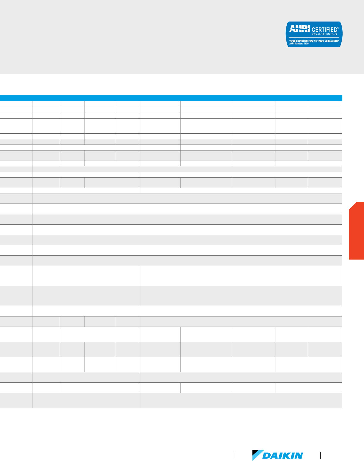
TECHNICAL DATA FOR VRV IV REYQ-TTJU/TYDN HEAT RECOVERY OUTDOOR UNITS
6 Ton 8 Ton 10 Ton 12 Ton
14 Ton
16 Ton 18 Ton 20 Ton 2 2 Ton 24 Ton 26 Ton 28 Ton 30 Ton 32 Ton 34 Ton 36 Ton 38 Ton
Model
208-230V/3Ph/60Hz REYQ72TTJU
REYQ96TTJU REYQ120TTJU REYQ144TTJU REYQ168T TJU
REYQ192TTJU REYQ216TTJU REYQ240TTJU REYQ264TTJU
REYQ288TTJU
REYQ312TTJU
REYQ336TTJU
REYQ360TTJU REYQ384T TJU REYQ408TTJU REYQ432TTJU REYQ456TTJU
460V/3Ph/60Hz
REYQ72TYDN
REYQ96TYDN
REYQ120TYDN
REYQ144TYDN REYQ168TYDN
REYQ192TYDN REYQ216TYDN REYQ240TYDN REYQ264TYDN
REYQ288TYDN
REYQ312TYDN
REYQ336TYDN
REYQ360TYDN REYQ384TYDN REYQ408TYDN REYQ432TYDN REYQ456TYDN
Combination
1 x REYQ120T
1 x REYQ72T
1 x R
EYQ120T
1 x REYQ96T
1 x REYQ144T
1 x REYQ96T
1 x REYQ144T
1 x REYQ120T
2 x REYQ144T
1 x REYQ168T
1 x REYQ144T
2 x REYQ168T 3 x REYQ120T
1 x REYQ168T
1 x REYQ120T
1 x REYQ96T
1 x R
EYQ168T
1 x REYQ144T
1 x REYQ96T
3 x REYQ144T
1 x REYQ168T
2 x REYQ144T
Performance
Rated Cooling Capacity BTU/h 67,000 90,000 111,000 134,000 156,000 180,000 200,000 222,000
246,000 268,000 290,000 312,000 334,000 356,000 380,000 400,000 415,000
Rated Heating Capacity BTU/h 75,000 100,000 126,000 150,000 176,000 200,000 226,000 250,000 276,000 300,000 326,000 352,000 376,000 415,000 415,000 425,000 435,000
Sound Pressure dB(A) 58 61 65 63 64 66 66 68 66 68 69 70
IEER (Ducted /
Non-Ducted)
20.8 / 26.2 21.0 / 29.3 20.7 / 25.4 20.7 / 24.2 19.5 / 22.0 20.4 / 22.9 20.2 / 22.9 19.2 / 21.9
18.1 / 21.6 18.2 / 21.4 17.8 / 20.2 17.0 / 19.0 17.9 / 19.6 16.6 / 18.3 16.5 / 17.2 16.5 / 16.2 15.9 / 16.2
Airflow CFM 5,544 5,827 6,286 8,228 5,544 + 6,286 5,827 + 6,286 5,827 + 8,228 6,286 + 8,228 8,228 + 8,228 8,228 + 8,228 6,286 + 6,286 + 6,286 5,827 + 6,286 + 8,228 5,827 + 8,228 + 8,228 8,228 + 8,228 + 8,228
Fan ESP, Standard/Max in. WG 0.12 / 0.32 0.12/0.32
Compressor
Compressors, all inverter Qty 1 2 3 4
4 6
Revolutions per minute RPM 3600 3630, 3630 4470, 4470 4440, 4440 5190, 5190 4080, (4290, 4290) (4170, 4170) x 2 (4050, 4050), (4110, 4110)
(4710, 4710),
(4800, 4800)
(4740, 4740)
x 2
(5190, 5190) x 2 (5010, 5010) x 3 (5070, 5070) x 2, (5160, 5160)
(5040, 5040),
(5130, 5130) x 2
(5220, 5220) x 3 (5730, 5730) x 3
Capacity Control Range % 15-100 11-100 10-100 5-100 5-100 3-100
Refrigerant
Piping,
Layout
Maximum Vertical Pipe
Length Above Unit
ft. 164 (295 With Field Setting)
164 (295 With Field Setting)
Maximum Vertical Pipe
Length Below Unit
ft. 131 (195 With Field Setting)
131 (195 With Field Setting)
Maximum Vertical Pipe
Length Between IDU
ft. 100
100
Maximum Actual
Pipe Length
ft. 541
541
Maximum Equivalent
Pipe Length
ft. 620
620
Maximum Total Pipe
Length
ft. 3,282
3,282
Refrigerant
Piping,
Connections
Liquid Pipe, Main Line in.
Φ3/8 (9.5) C1220T
(Brazing Connection)
Φ1/2 (12.7) C1220T
(Brazing Connection)
Φ5/8 (15.9) C1220T (Brazing Connection)
Φ3/4 (19.1) C1220T (Brazing Connection)
Suction Gas Pipe,
Main Line
in.
Φ3/4 (19.1)
C1220T
(Brazing
Connection)
Φ7/8 (22.2)
C1220T
(Brazing
Connection)
Φ1-1/8 (28.6) C1220T (Brazing Connection)
Φ1-3/8 (34.9) C1220T
(Brazing Connection)
Φ1-3/8 (34.9) C1220T (Brazing Connection) Φ1-5/8 (41.3) C1220T (Brazing Connection)
Discharge Gas Pipe,
Main Line
in.
Φ5/8 (15.9)
C1220T
(Brazing
Connection)
Φ3/4 (19.1) C1220T
(Brazing Connection)
Φ7/8 (22.2) C1220T
(Brazing Connection)
Φ1-1/8 (28.6) C1220T (Brazing Connection)
Φ1-1/8 (28.6) C1220T (Brazing Connection) Φ1-3/8 (34.9) C1220T (Brazing Connection)
Connection
Ratio
Standard Connectable
Indoor Unit Ratio
% 50 - 200
50 - 200
Maximum Number of
Indoor Units
Qty 12 16 20 25 29 33 37 41
45 49 54 58 64
Electrical
Maximum Overcurrent
Protection, MOP
(REYQ-TT / REYQ-TY)
A 35/20 45/25 50/25 70/40 35 + 50 / 20 + 25 45 + 50 / 25 + 25 45 + 70 / 25 + 40
50 + 70 / 25 + 40 70 + 70 / 40 + 40 50 + 50 + 50 / 25 + 25 + 25 45 + 50 + 70 / 25 + 25 + 40 45 + 70 + 70 / 25 + 40 + 40
70 + 70 + 70 /
40 + 40 + 40
7
0 + 70 + 70 /
40 + 40 + 40
Minimum Circuit
Amps, MCA
(REYQ-TT / REYQ-TY)
A 30.2 / 15.2 38 / 21.1 43 / 21.1 55 / 31.9 61.9 / 36.1 30.2 + 43 / 15.2 + 21.1 38 + 43 / 21.1 + 21.1 38 + 55 / 21.1 + 31.9
43 + 55 / 21.1
+ 31.9
55 + 55 /
31.9 + 31.9
55 + 61.9 /
31.9 + 36.1
61.9 + 61.9 /
36.1 + 36.1
43 + 43 + 43 /
21.1 + 21.1 + 21.1
38 + 43 + 61.9 / 21.1 + 21.1 + 21.1
38 + 55 + 61.9 /
21.1 + 31.9 + 36.1
55 + 55 + 55 /
31.9 + 31.9 + 31.9
55 + 55 + 61.9 /
31.9 + 31.9 + 36.1
Compressor Rated
Load Amps, RLA
(REYQ-TT / REYQ-TY)
A 20.7 / 9.4
13.7 + 13.7 /
6.2 + 6.2
15 + 15 /
6.8 + 6.8
16.2 + 22.6 /
7.3 + 10.3
17.4 + 24.4 /
7.9 + 11.1
20.7 + (15 + 15) /
9.4 + (6.8 + 6.8)
(13.7 + 13.7) + (15 + 15) /
(6.2 + 6.2) + (6.8 + 6.8)
(13.7 + 13.7) + (16.2 + 22.6) /
(6.2 + 6.2) + (7.3 + 10.3)
(15 + 15) + (16.2 +
22.6) / (6.8 + 6.8)
+ (7.3 + 10.3)
(16.2 + 22.6
x 2 /
(7.3 + 10.3) x 2
(16.2 + 22.6) + (17.4
+ 24.4) / (7.3 + 10.3)
+ (7.9 + 11.1)
(17.4 + 24.4)
x 2 / (7.9 +
11.1) x 2
(15 + 15) x 3 /
(6.8 + 6.8) x 3
(13.7 + 13.7) + (16.2 + 22.6) + (17.4
+ 24.4) / (6.2 + 6.2) + (6.8 + 6.8) +
(7.9 + 11.1)
(13.7 + 13.7) + (16.2 + 22.6)
+ (17.4 + 24.4) / (6.2 + 6.2) +
(7.3 + 10.3) + (7.9 + 11.1)
(16.2 + 22.6) x 3 /
(7.3 + 10.3) x 3
(16.2 + 22.6) x 2 +
(17.4 + 24.4) / (7.3 +
10.3) x 2 + (7.9 + 11.1)
Unit
Factory Refrigerant
Charge
lbs 21.9 25.8 21.9 + 25.8 25.8 + 25.8
25.8 + 25.8 25.8 + 25.8 + 25.8
Weight (REYQ-TT /
REYQ-TY)
lbs 507 / 527 703 / 717 703 / 717 780 / 794 507 + 703 / 527 + 717 703 + 703 / 717 + 717 703 + 780 / 717 + 794
703 + 780 / 717
+ 794
780 + 780 / 794 + 794
703 + 703 + 703
/ 717 + 717 + 717
703 + 703 + 780 / 717 + 717 + 794
780 + 780 + 780
/ 717 + 794 + 794
780 + 780 + 780
/ 794 + 794 + 794
Dimensions (H x W x D) in.
66-11/16 x
36-11/16 x
30-3/16
66-11/16 x 48-7/8 x 30-3/16
(66-11/16 x 36-11/16 x
30-3/16) + (66-11/16 x
36-11/16 x 30-3/16)
(66-11/16 x 48-7/8 x 30-3/16) +
(66-11/16 x 48-7/8 x 30-3/16)
(66-11/16 x 48-7/8 x 30-3/16) + (66-11/16 x 48-7/8 x 30-3/16) (66-11/16 x 48-7/8 x 30-3/16) + (66-11/16 x 48-7/8 x 30-3/16) + (66-11/16 x 48-7/8 x 30-3/16)
For additional technical information please refer to specific Engineering Data Books.
VRV Product Catalog
79
OUTDOOR UNITS
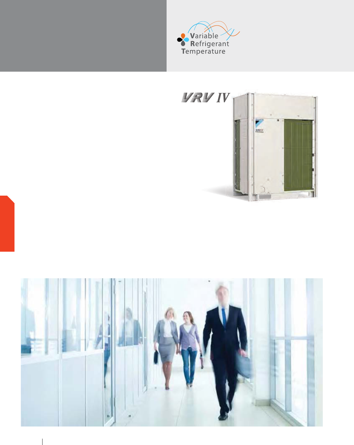
VRV IV
Air-Cooled
Heat Pump
Daikin’s VRV IV systems integrate advanced technology to
provide comfort control to help maximize energy efficiency and
reliability. VRV IV provides a solution for multi-family residential
to large commercial applications desiring heating or cooling. The
VRV IV is the first variable refrigerant flow (VRF) system to be
assembled in North America.
Features and Benefits
Total comfort solution for heating, cooling, ventilation
and controls
Redesigned and optimized for total Life Cycle Cost (LCC)
Reduced install cost and increased flexibility as compared to
VRV III with larger capacity single modules up to 14 Tons and
system capacity up to 34 Tons
Efficiency improved over VRV III by an average of 11% with
IEER Values now up to 28
Improved seasonal efficiency as compared to VRV III with
automatic and customizable Variable Refrigerant Temperature
(VRT) climate tuning
Outstanding warranty* with 10 year compressor and parts
limited warranty as standard
Reduced commissioning time vs. VRV III with VRV configurator
software and Graphical User Interface (GUI)
Design flexibility with long piping lengths up to 3,280 ft. total
and 100 ft. vertical separation between indoor units
Take advantage of Daikin’s unique zone and centralized controls
that are optimized for the specific needs of North America
*
Complete warranty details available from your local distributor
or manufacturer’s representative or at www.daikincomfort.com.
www.daikincomfort.com80
OUTDOOR UNITS
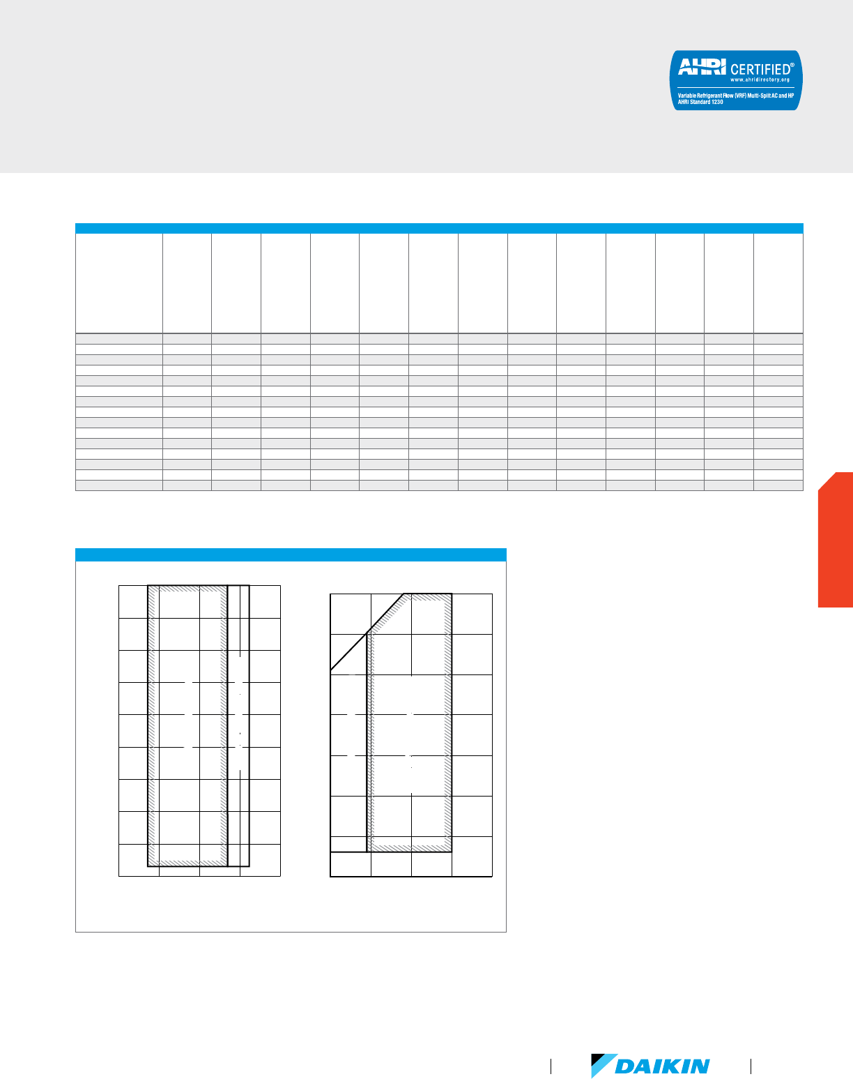
VRV IV CERTIFIED DATA - HEAT PUMP, 208-230V/60HZ/3PH AND 460V/60HZ/3PH
Product #
Capacity (Tons)
IEER Non-Ducted
IEER Ducted
IEER Mixed
COP @ 47°F Non-Ducted
COP @ 47°F Ducted
COP @ 47°F Mixed
COP @ 17°F Non-Ducted
COP @ 17°F Ducted
COP @ 17°F Mixed
EER Non-Ducted
EER Ducted
EER Mixed
RXYQ72T 6 26.50 22.80 24.65 4.21 3.58 3.90 2.49 2.25 2.37 15.00 13.50 14.25
RXYQ96T 8 28.00 22.70 25.35 4.59 3.99 4.29 2.86 2.61 2.74 15.10 13.00 14.05
RXYQ120T 10 23.50 21.40 22.45 3.79 3.46 3.63 2.61 2.58 2.60 13.20 12.10 12.65
RXYQ144T 12 24.10 21.00 22.55 4.10 3.72 3.91 2.33 2.20 2.27 12.30 11.50 11.90
RXYQ168T 14 22.10 19.80 20.95 3.74 3.49 3.62 2.27 2.27 2.31 10.60 10.60 10.60
RXYQ192T 16 22.20 20.70 21.45 3.80 3.60 3.70 2.62 2.40 2.34 11.90 12.30 12.10
RXYQ216T 18 20.50 20.00 20.25 3.83 3.65 3.74 2.62 2.48 2.55 11.60 11.70 11.65
RXYQ240T 20 20.80 18.40 19.60 3.63 3.55 3.59 2.62 2.43 2.53 11.50 11.60 11.55
RXYQ264T 22 20.30 19.30 19.80 3.33 3.35 3.34 2.43 2.30 2.37 10.90 10.50 10.70
RXYQ288T 24 20.10 19.30 19.70 3.25 3.31 3.28 2.07 2.13 2.10 10.50 10.50 10.50
RXYQ312T 26 19.90 18.80 19.35 3.30 3.26 3.28 2.32 2.20 2.26 9.80 9.80 9.80
RXYQ336T 28 19.50 19.00 19.00 3.22 3.20 3.21 2.38 2.27 2.33 9.50 9.50 9.50
RXYQ360T 30 19.40 18.50 18.95 3.46 3.25 3.36 2.47 2.41 2.44 10.30 10.90 10.60
RXYQ384T 32 20.40 18.50 19.45 3.30 3.26 3.28 2.28 2.28 2.28 9.50 10.00 9.75
RXYQ408T 34 20.90 19.00 19.95 3.24 3.24 3.24 2.18 2.10 2.14 9.50 9.50 9.50
Certified efficiency data in accordance with ANSI/AHRI Standard 1230 2010, “Performance Rating of Variable Refrigerant Flow (VRF) Multi-Split Air Conditioning and Heat Pump Equipment” for the VRV Series. The
VRV IV Series has been designed and optimized to meet or exceed the latest minimum efficiency requirements in 10 C.F.R. Part 431 as determined by the U.S. Department of Energy (DOE) and baseline efficiencies as
defined by ASHRAE 90.1 2010. Systems under 65MBH are currently certified to AHRI 210/240. IEER ratings are as defined in ASHRAE 90.1 2010.
DETAILED OPERATION RANGES FOR VRV IV RXYQ-T HEAT PUMP OUTDOOR UNITS
See the Engineering Data book for complete application rules.
50 60 70 80 90
Indoor temperature (˚F WB)
110
100
90
Cooling
Outdoor temperature (˚F DB)
20
80
70
60
50
40
30
Range for pull-down operationRange for pull-down operation
Range for continuous operation
Range for continuous operation
50 60 70 80
90
Indoor temperature (˚F DB)
60
50
Heating
Outdoor temperature (˚F WB)
40
30
20
10
0
-10
Range for continuous operation Range for continuous operation
Range for warming up operation Range for warming up operation
VRV Product Catalog
81
OUTDOOR UNITS
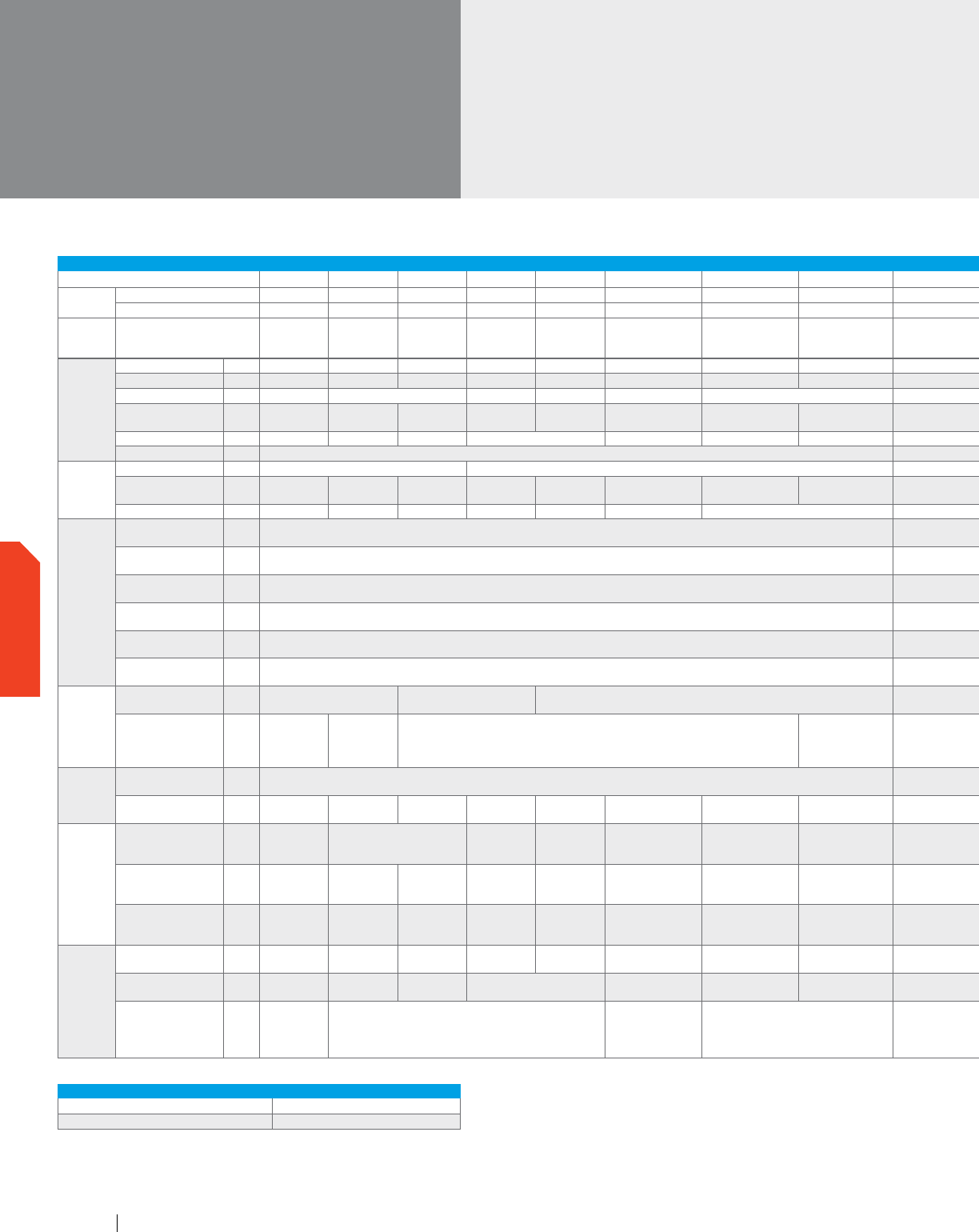
VRV IV
Air-Cooled
Heat Pump (continued)
TECHNICAL DATA FOR VRV IV RXYQ-TTJU/TYDN HEAT PUMP OUTDOOR UNITS
6 Ton 8 Ton 10 Ton 12 Ton
14 Ton
16 Ton 18 Ton 20 Ton 22 Ton 24 Ton 26 Ton 28 Ton 3 0 Ton 32 Ton 34 Ton
Model
208-230V/3Ph/60Hz RXYQ72TTJU RXYQ96TTJU
RXYQ120TTJU
RX YQ144TTJU
RX YQ168TTJU
RX YQ192TTJU RXYQ216TTJU RXYQ240TTJU RXYQ264TTJU RXYQ288TTJU RXYQ312TTJU RXYQ336TTJU RXYQ360TTJU RXYQ384TTJU RXYQ408TTJU
460V/3Ph/60Hz RXYQ72TYDN
RXYQ96TYDN
RXYQ120TYDN
RXYQ144TYDN
RXYQ168TYDN
RXYQ192TYDN RXYQ216TYDN RXYQ240TYDN RXYQ264TYDN RXYQ288TYDN RXYQ312TYDN RXYQ336TYDN RXYQ360TYDN RXYQ384TYDN RXYQ408TYDN
Combination
1 x RXYQ120T
1 x RXYQ72T
1 x R
XYQ120T
1 x RXYQ96T
2 x RXYQ120T
1 x RXYQ144T
1 x RXYQ120T
2 x RXYQ144T
1 x RXYQ168T
1 x RXYQ144T
2 x RXYQ168T 3 x RXYQ120T
1 x RXYQ168T
1 x RXYQ120T
1 x RXYQ96T
1 x R
XYQ168T
1 x RXYQ144T
1 x RXYQ96T
Performance
Rated Cooling Capacity BTU/h 69,000 92,000 114,000 138,000 160,000 184,000 206,000 228,000
251,000 274,000 297,000 320,000 342,000 365,000 380,000
Rated Heating Capacity BTU/h 77,000 103,000 129,000 154,000 180,000 206,000 231,000 257,000 283,000 308,000 334,000 360,000 385,000 411,000 436,000
Sound Pressure dB(A) 58 61 64 65 63 64 66 67 68 66 68
IEER (Ducted /
Non-Ducted)
22.8 / 26.5 22.7 / 28 21.4 / 23.5 21 / 24.1 19.8 / 22.1 20.7 / 22.2 20 / 20.5 18.4 / 20.8
19.3 / 20.3 19.3 / 20.1 18.8 / 19.9 18.5 / 19.5 18.5 / 19.4 18.5 / 20.4 19.0 / 20.9
Airflow CFM 5,544 5,827 6286 8,228 5544 + 6286 5827 + 6286 6286 + 6286 6286 + 8228 8228 + 8228 6286 + 6286 + 6286 5827 + 6286 + 8228 5827 + 8228 + 8228
Fan ESP, Standard/Max in. WG 0.12 / 0.32 0.12 / 0.32
Compressor
Compressors, all inverter Qty 1 2
3 4 3 4 5
Revolutions per minute RPM 7668 7650 7746 7008 + 7608 7680 + 8280 7668, 7746 7650, 7746 7746, 7746 7746, (7008, 7608)
(7008, 7608),
(7008, 7608)
(
7008, 7608), (7680, 8280)
(7680, 8280),
(7680, 8280)
7746, 7746, 7746 7650, 7746, (7680, 8280) 7650, (7008, 7608), (7680, 8280)
Capacity Control Range % 20-100 16-100 15-100 11-100 10-100 17-100 15-100 13-100 11-100 10-100 15-100 13-100 12-100
Refrigerant
Piping,
Layout
Maximum Vertical Pipe
Length Above Unit
ft. 164 (295 With Field Setting)
164 (295 With Field Setting)
Maximum Vertical Pipe
Length Below Unit
ft. 131 (295 With Field Setting)
131 (295 With Field Setting)
Maximum Vertical Pipe
Length Between IDU
ft. 100
100
Maximum Actual
Pipe Length
ft. 541
541
Maximum Equivalent
Pipe Length
ft. 620
620
Maximum Total Pipe
Length
ft. 3,282
3,282
Refrigerant
Piping,
Connections
Liquid Pipe, Main Line in.
Φ3/8 (9.5) C1220T
(Brazing Connection)
Φ1
/2 (12.7) C1220T
(Brazing Connection)
Φ5/8 (15.9) C1220T (Brazing Connection) Φ3/4 (19.1) C1220T (Brazing Connection)
Suction Gas Pipe,
Main Line
in.
Φ3/4 (19.1)
C1220T
(Brazing
Connection)
Φ7/8 (22.2)
C1220T
(Brazing
Connection)
Φ1-1/8 (28.6) C1220T (Brazing Connection)
Φ1-3/8 (34.9) C1220T
(Brazing Connection)
Φ1-3/8 (34.9) C1220T (Brazing Connection) Φ1-5/8 (41.3) C1220T (Brazing Connection)
Connection
Ratio
Standard Connectable
Indoor Unit Ratio
% 50 - 200
50 - 200
Maximum Number of
Indoor Units
Qty 12 16 20 25 29 33 37 41
45 49 54 58 62 64
Electrical
Maximum Overcurrent
Protection, MOP
(RXYQ-TT / RXYQ-T Y)
A 35 / 20 45 / 25 60 / 35 60 / 35 35 + 45 / 20 + 25 45 + 45 / 25+25 45 + 45 / 25 + 25
45 + 60 / 25 + 35 60 + 60 / 35 + 35 45 + 45 + 45 / 25 + 25 + 25 45 + 45 + 60 / 25 + 25 + 35 45 + 60 + 60 / 25 + 35 + 35
Minimum Circuit Amps,
MCA
(RXYQ-TT / RXYQ-T Y)
A
27.6 /
12.3
36.3 /
20.6
36.3 /
20.6
55.1 /
25.9
55.1 /
25.9
27.6 + 36.3 /
12.3 + 20.6
36.3 + 36.3 /
20.6 + 20.6
36.3 + 36.3 /
20.6 + 20.6
36.3 + 55.1 / 20.6 + 25.9 55.1 + 55.1 / 25.9 + 25.9
36.3 + 36.3 + 36.3 /
20.6 + 20.6 + 20.6
3
6.3 + 36.3 + 55.1 /
20.6 + 20.6 + 25.9
36.3 + 55.1 + 55.1 /
20.6 + 25.9 + 25.9
Compressor Rated Load
Amps, RLA
(RXYQ-TT / RXYQ-T Y)
A
15.7 /
7.1
23.8 /
10.2
26.2 /
11.7
16.7 + 16.7 /
7.6 + 7.6
18.8 + 18.8 /
8.5 + 8.5
15.7 + 26.2 /
7.1 + 11.7
23.8 + 26.2 /
10.2 + 11.7
26.2 + 26.2 /
11.7 + 11.7
26.2 + (16.7 + 16.7) /
11.7 + (7.6 + 7.6)
(16.7 + 16.7) x 2 /
(7.6 + 7.6) x 2
(16.7 + 16.7) +
(18.8 + 18.8) /
(7.6 + 7.6) + (8.5 + 8.5)
(
18.8 + 18.8) x
2 / (8.5 + 8.5) x 2
26.2 + 26.2 + 26.2 /
11.7 + 11.7 + 11.7
23.8 + 26.2 + (18.8 + 18.8) /
10.2 + 11.7 + (8.5 + 8.5)
23.8 + (16.7 + 16.37) +
(18.8 + 18.8) / 10.2 + (7.6 + 7.6)
+ (8.5 + 8.5)
Unit
Factory Refrigerant
Charge
lbs 13 22.7 22.9 18.1 17.2 13.0 + 22.9 22.7 + 22.9 22.9 + 22.9
22.9 + 18.1 18.1 + 18.1 18.1 + 17.2 17.2 + 17.2 22.9 + 22.9 + 22.9 22.7 + 22.9 + 17.2 22.7 + 18.1 + 17.2
Weight (RXYQ-TT /
RXYQ-TY)
lbs 435 / 451 525 / 553 528 / 556 695 / 709 435 + 528 / 451 + 556 525 + 528 / 553 + 556 528 + 528 / 566 + 556
528 + 695 / 556 + 709 695 + 695 / 709 + 709
528 + 528 + 528 /
556 + 556 + 556
5
25 + 528 + 695 /
553 + 556 + 709
525 + 695 + 695 /
553 + 709 + 709
Dimensions (H x W x D) in.
66-11/16 ×
36-11/16 ×
30-3/16
66-11/16 × 48-7/8 × 30-3/16
66-11/16 × 36-11/16 ×
30-3/16 +
66-11/16 × 48-7/8 ×
30-3/16
66-11/16 × 48-7/8 × 30-3/16 +
66-11/16 × 48-7/8 × 30-3/16
(66-11/16 x 48-7/8 x 30-3/16) + (66-11/16 x 48-7/8 x 30-3/16) (66-11/16 x 48-7/8 x 30-3/16) + (66-11/16 x 48-7/8 x 30-3/16) + (66-11/16 x 48-7/8 x 30-3/16)
OPERATION RANGE FOR ALL VRV IV HEAT PUMP OUTDOOR UNITS
Cooling °F DB 23 – 122
Heating °F WB -4 – 60
www.daikincomfort.com82
OUTDOOR UNITS
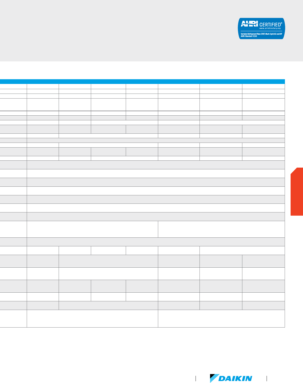
TECHNICAL DATA FOR VRV IV RXYQ-TTJU/TYDN HEAT PUMP OUTDOOR UNITS
6 Ton 8 Ton 10 Ton 12 Ton
14 Ton
16 Ton 18 Ton 20 Ton 22 Ton 24 Ton 26 Ton 28 Ton 3 0 Ton 32 Ton 34 Ton
Model
208-230V/3Ph/60Hz RXYQ72TTJU RXYQ96TTJU
RXYQ120TTJU
RX YQ144TTJU
RX YQ168TTJU
RX YQ192TTJU RXYQ216TTJU RXYQ240TTJU RXYQ264TTJU RXYQ288TTJU RXYQ312TTJU RXYQ336TTJU RXYQ360TTJU RXYQ384TTJU RXYQ408TTJU
460V/3Ph/60Hz RXYQ72TYDN
RXYQ96TYDN
RXYQ120TYDN
RXYQ144TYDN
RXYQ168TYDN
RXYQ192TYDN RXYQ216TYDN RXYQ240TYDN RXYQ264TYDN RXYQ288TYDN RXYQ312TYDN RXYQ336TYDN RXYQ360TYDN RXYQ384TYDN RXYQ408TYDN
Combination
1 x RXYQ120T
1 x RXYQ72T
1 x R
XYQ120T
1 x RXYQ96T
2 x RXYQ120T
1 x RXYQ144T
1 x RXYQ120T
2 x RXYQ144T
1 x RXYQ168T
1 x RXYQ144T
2 x RXYQ168T 3 x RXYQ120T
1 x RXYQ168T
1 x RXYQ120T
1 x RXYQ96T
1 x R
XYQ168T
1 x RXYQ144T
1 x RXYQ96T
Performance
Rated Cooling Capacity BTU/h 69,000 92,000 114,000 138,000 160,000 184,000 206,000 228,000
251,000 274,000 297,000 320,000 342,000 365,000 380,000
Rated Heating Capacity BTU/h 77,000 103,000 129,000 154,000 180,000 206,000 231,000 257,000 283,000 308,000 334,000 360,000 385,000 411,000 436,000
Sound Pressure dB(A) 58 61 64 65 63 64 66 67 68 66 68
IEER (Ducted /
Non-Ducted)
22.8 / 26.5 22.7 / 28 21.4 / 23.5 21 / 24.1 19.8 / 22.1 20.7 / 22.2 20 / 20.5 18.4 / 20.8
19.3 / 20.3 19.3 / 20.1 18.8 / 19.9 18.5 / 19.5 18.5 / 19.4 18.5 / 20.4 19.0 / 20.9
Airflow CFM 5,544 5,827 6286 8,228 5544 + 6286 5827 + 6286 6286 + 6286 6286 + 8228 8228 + 8228 6286 + 6286 + 6286 5827 + 6286 + 8228 5827 + 8228 + 8228
Fan ESP, Standard/Max in. WG 0.12 / 0.32 0.12 / 0.32
Compressor
Compressors, all inverter Qty 1 2
3 4 3 4 5
Revolutions per minute RPM 7668 7650 7746 7008 + 7608 7680 + 8280 7668, 7746 7650, 7746 7746, 7746 7746, (7008, 7608)
(7008, 7608),
(7008, 7608)
(
7008, 7608), (7680, 8280)
(7680, 8280),
(7680, 8280)
7746, 7746, 7746 7650, 7746, (7680, 8280) 7650, (7008, 7608), (7680, 8280)
Capacity Control Range % 20-100 16-100 15-100 11-100 10-100 17-100 15-100 13-100 11-100 10-100 15-100 13-100 12-100
Refrigerant
Piping,
Layout
Maximum Vertical Pipe
Length Above Unit
ft. 164 (295 With Field Setting)
164 (295 With Field Setting)
Maximum Vertical Pipe
Length Below Unit
ft. 131 (295 With Field Setting)
131 (295 With Field Setting)
Maximum Vertical Pipe
Length Between IDU
ft. 100
100
Maximum Actual
Pipe Length
ft. 541
541
Maximum Equivalent
Pipe Length
ft. 620
620
Maximum Total Pipe
Length
ft. 3,282
3,282
Refrigerant
Piping,
Connections
Liquid Pipe, Main Line in.
Φ3/8 (9.5) C1220T
(Brazing Connection)
Φ1
/2 (12.7) C1220T
(Brazing Connection)
Φ5/8 (15.9) C1220T (Brazing Connection) Φ3/4 (19.1) C1220T (Brazing Connection)
Suction Gas Pipe,
Main Line
in.
Φ3/4 (19.1)
C1220T
(Brazing
Connection)
Φ7/8 (22.2)
C1220T
(Brazing
Connection)
Φ1-1/8 (28.6) C1220T (Brazing Connection)
Φ1-3/8 (34.9) C1220T
(Brazing Connection)
Φ1-3/8 (34.9) C1220T (Brazing Connection) Φ1-5/8 (41.3) C1220T (Brazing Connection)
Connection
Ratio
Standard Connectable
Indoor Unit Ratio
% 50 - 200
50 - 200
Maximum Number of
Indoor Units
Qty 12 16 20 25 29 33 37 41
45 49 54 58 62 64
Electrical
Maximum Overcurrent
Protection, MOP
(RXYQ-TT / RXYQ-T Y)
A 35 / 20 45 / 25 60 / 35 60 / 35 35 + 45 / 20 + 25 45 + 45 / 25+25 45 + 45 / 25 + 25
45 + 60 / 25 + 35 60 + 60 / 35 + 35 45 + 45 + 45 / 25 + 25 + 25 45 + 45 + 60 / 25 + 25 + 35 45 + 60 + 60 / 25 + 35 + 35
Minimum Circuit Amps,
MCA
(RXYQ-TT / RXYQ-T Y)
A
27.6 /
12.3
36.3 /
20.6
36.3 /
20.6
55.1 /
25.9
55.1 /
25.9
27.6 + 36.3 /
12.3 + 20.6
36.3 + 36.3 /
20.6 + 20.6
36.3 + 36.3 /
20.6 + 20.6
36.3 + 55.1 / 20.6 + 25.9 55.1 + 55.1 / 25.9 + 25.9
36.3 + 36.3 + 36.3 /
20.6 + 20.6 + 20.6
3
6.3 + 36.3 + 55.1 /
20.6 + 20.6 + 25.9
36.3 + 55.1 + 55.1 /
20.6 + 25.9 + 25.9
Compressor Rated Load
Amps, RLA
(RXYQ-TT / RXYQ-T Y)
A
15.7 /
7.1
23.8 /
10.2
26.2 /
11.7
16.7 + 16.7 /
7.6 + 7.6
18.8 + 18.8 /
8.5 + 8.5
15.7 + 26.2 /
7.1 + 11.7
23.8 + 26.2 /
10.2 + 11.7
26.2 + 26.2 /
11.7 + 11.7
26.2 + (16.7 + 16.7) /
11.7 + (7.6 + 7.6)
(16.7 + 16.7) x 2 /
(7.6 + 7.6) x 2
(16.7 + 16.7) +
(18.8 + 18.8) /
(7.6 + 7.6) + (8.5 + 8.5)
(
18.8 + 18.8) x
2 / (8.5 + 8.5) x 2
26.2 + 26.2 + 26.2 /
11.7 + 11.7 + 11.7
23.8 + 26.2 + (18.8 + 18.8) /
10.2 + 11.7 + (8.5 + 8.5)
23.8 + (16.7 + 16.37) +
(18.8 + 18.8) / 10.2 + (7.6 + 7.6)
+ (8.5 + 8.5)
Unit
Factory Refrigerant
Charge
lbs 13 22.7 22.9 18.1 17.2 13.0 + 22.9 22.7 + 22.9 22.9 + 22.9
22.9 + 18.1 18.1 + 18.1 18.1 + 17.2 17.2 + 17.2 22.9 + 22.9 + 22.9 22.7 + 22.9 + 17.2 22.7 + 18.1 + 17.2
Weight (RXYQ-TT /
RXYQ-TY)
lbs 435 / 451 525 / 553 528 / 556 695 / 709 435 + 528 / 451 + 556 525 + 528 / 553 + 556 528 + 528 / 566 + 556
528 + 695 / 556 + 709 695 + 695 / 709 + 709
528 + 528 + 528 /
556 + 556 + 556
5
25 + 528 + 695 /
553 + 556 + 709
525 + 695 + 695 /
553 + 709 + 709
Dimensions (H x W x D) in.
66-11/16 ×
36-11/16 ×
30-3/16
66-11/16 × 48-7/8 × 30-3/16
66-11/16 × 36-11/16 ×
30-3/16 +
66-11/16 × 48-7/8 ×
30-3/16
66-11/16 × 48-7/8 × 30-3/16 +
66-11/16 × 48-7/8 × 30-3/16
(66-11/16 x 48-7/8 x 30-3/16) + (66-11/16 x 48-7/8 x 30-3/16) (66-11/16 x 48-7/8 x 30-3/16) + (66-11/16 x 48-7/8 x 30-3/16) + (66-11/16 x 48-7/8 x 30-3/16)
For additional technical information please refer to specific Engineering Data Books.
VRV Product Catalog
83
OUTDOOR UNITS
VRV-III PC
Air-Cooled
Heat Recovery
Daikin’s VRV III systems integrate advanced technology to
provide comfort control to help maximize energy efficiency.
Available in heat recovery configurations, VRV III provides a
solution for residential to large commercial applications desiring
heating, cooling, or simultaneous operation.
Features and Benefits
Advanced continuous heating during defrost cycle
and oil return for single module systems
Variable Refrigerant Temperature (VRT) control
Extended operating range with heating
function -4°F ambient air temperature
VRV III PC CERTIFIED DATA - HEAT RECOVERY, 208-230V/60HZ/3PH AND 460V/3PH/60HZ
Product #
Capacity (Tons)
IEER Non-Ducted
IEER Ducted
IEER Mixed
COP @ 47°F Non-Ducted
COP @ 47°F Ducted
COP @ 47°F Mixed
COP @ 17°F Non-Ducted
COP @ 17°F Ducted
COP @ 17°F Mixed
EER Non-Ducted
EER Ducted
EER Mixed
REYQ72PC 6 25.1 18.7 21.9 4.2 3.6 3.9 2.95 2.4 2.7 15.4 12.3 13.9
REYQ96PC 8 22.9 17.6 20.3 3.7 3.4 3.6 2.7 2.4 2.6 13.2 11.0 12.1
REYQ120PC 10 21.3 15.3 18.3 3.6 3.2 3.4 2.6 2.95 2.4 12.1 10.9 11.5
REYQ144PCTJ 12 18.9 15.3 17.1 3.6 3.2 3.4 2.95 2.95 2.3 11.2 10.0 10.6
Certified efficiency data in accordance with ANSI/AHRI Standard 1230 2010, “Performance Rating of Variable Refrigerant Flow (VRF) Multi-Split Air Conditioning and Heat Pump Equipment” for the VRV Series. The
VRV III Series has been designed and optimized to meet or exceed the latest minimum efficiency requirements in 10 C.F.R. Part 431 as determined by the U.S. Department of Energy (DOE) and baseline efficiencies as
defined by ASHRAE 90.1 2010. Systems under 65MBH are currently certified to AHRI 210/240. IEER ratings are as defined in ASHRAE 90.1 2010.
www.daikincomfort.com84
OUTDOOR UNITS
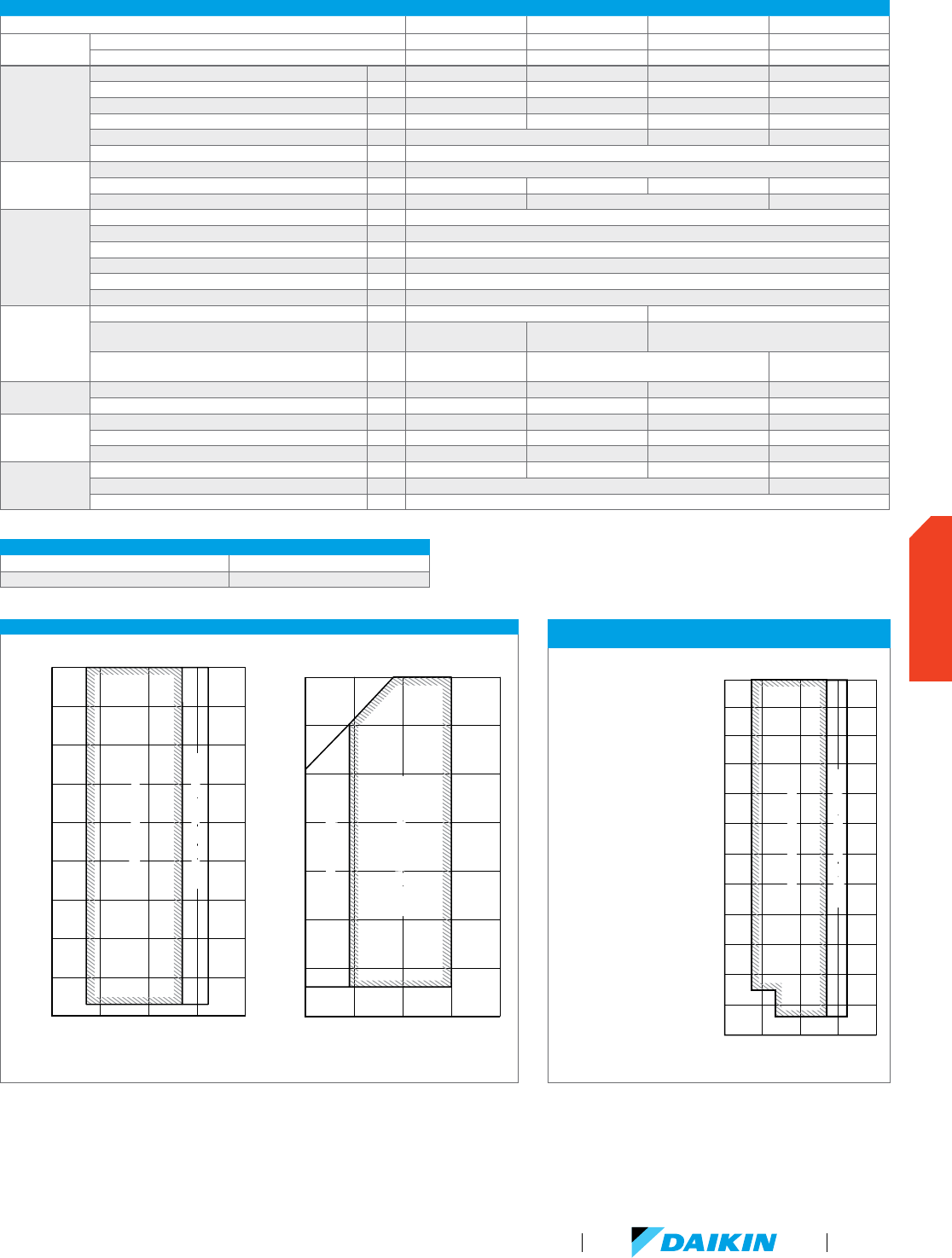
For additional technical information please refer to specific Engineering Data Books.
OPERATION RANGE FOR ALL VRV III PC HEAT RECOVERY OUTDOOR UNITS
Cooling °F DB 23 – 122
Heating °F WB -4 – 60
TECHNICAL COOLING FEATURE FOR
VRV III PC (REYQ-PC) HEAT RECOVERY OUTDOOR UNITS
Technical Cooling - Cooling
operation extended from
23°F ambient air temperature
down to -4°F
The Technical Cooling feature
is engaged by field settings
on the outdoor unit and on
branch selector boxes. It
requires addition of wind
covers to the unit and allows
operation down to -4° FDB
ambient temperature in
cooling mode.
See the Engineering Data
book for complete application
rules and contact your local
Daikin representative for
wind cover specification
requirements.
DETAILED OPERATION RANGES FOR VRV III PC (REYQ-PC) HEAT RECOVERY OUTDOOR UNITS
See the Engineering Data book for complete application rules.
50 60 70 80 90
Indoor temperature (˚F WB)
110
100
90
Cooling
Outdoor temperature (˚F DB)
20
80
70
60
50
40
30
Range for pull-down operationRange for pull-down operation
Range for continuous operation
Range for continuous operation
50 60 70 80
90
Indoor temperature (˚F DB)
60
50
Heating
Outdoor temperature (˚F WB)
40
30
20
10
0
-10
Range for continuous operation Range for continuous operation
Range for warming up operation Range for warming up operation
60 70 80
Indoor temperature (˚F WB)
110
100
90
Ambient temperature (˚F DB)
20
10
0
-10
80
70
60
50
40
30
Range for pull-down operationRange for pull-down operation
Range for continuous operation
Range for continuous operation
Cooling
TECHNICAL DATA FOR VRV III PC REYQ-PC HEAT RECOVERY OUTDOOR UNITS
6 Ton 8 Ton 10 Ton 12 Ton
Model
208-230V/3Ph/60Hz REYQ72PCTJ REYQ96PCTJ REYQ120PCTJ REYQ144PCTJ
460V/3Ph/60Hz REYQ72PCYD REYQ96PCYD REYQ120PCYD –
Performance
Rated Cooling Capacity BTU/h 69,000 92,000 114,000 138,000
Rated Heating Capacity BTU/h 77,000 103,000 129,000 154,000
Sound Pressure (REYQ-PCT / REYQ-PCY) dB(A) 58 / 58 58 / 61 60 / 61 62 / –
IEER (Ducted / Non-Ducted) 18.7 / 25.1 17.6 / 22.9 15.3 / 21.3 15.3 / 18.9
Airflow CFM 6,700 7,410 8,300
Fan ESP, Standard/Max in. WG 0.12 / 0.32
Compressor
Compressors, standard / inverter Qty 2
Revolutions per minute RPM 3720, 2900 6300, 2900 6300, 2900 7980, 7880
Capacity Control Range % 20–100 14–100 10–100
Refrigerant Piping,
Layout
Maximum Vertical Pipe Length Above Unit ft. 131 (295 With Field Setting)
Maximum Vertical Pipe Length Below Unit ft. 164 (295 With Field Setting)
Maximum Vertical Pipe Length Between IDU ft. 49
Maximum Actual Pipe Length ft. 541
Maximum Equivalent Pipe Length ft. 620
Maximum Total Pipe Length ft. 3,282
Refrigerant Piping,
Connections
Liquid Pipe, Main Line in.
Φ3/8 (9.5) C1220T (Brazing Connection) Φ1/2 (12.7) C1220T (Brazing Connection)
Suction Gas Pipe, Main Line in.
Φ3/4 (19.1) C1220T
(Brazing Connection)
Φ7/8 (22.2) C1220T
(Brazing Connection)
Φ1-1/8 (28.6) C1220T (Brazing Connection)
Discharge Gas Pipe, Main Line in.
Φ5/8 (15.9) C1220T
(Brazing Connection)
Φ3/4 (19.1) C1220T (Brazing Connection)
Φ7/8 (22.2) C1220T
(Brazing Connection)
Connection Ratio
Standard Connectable Indoor Unit Ratio % 36–93 48–124 60–156 72–187
Maximum Number of Indoor Units Qty 12 16 20 25
Electrical
Maximum Overcurrent Protection, MOP (REYQ-PCT / REYQ-PCY) A 40 / 20 45 / 25 50 / 25 80 / –
Minimum Circuit Amps, MCA (REYQ-PCT / REYQ-PCY) A 36.1 / 16.0 43.8 / 20.4 44.2 / 20.5 72.2 / –
Compressor Rated Load Amps, RLA (REYQ-PCT / REYQ-PCY) A 4.8 + 14.0 / 2.4 + 7.0 8.4 + 14.0 / 4.2 + 7.0 12.0 + 13.6 / 6.0 + 6.8 14.3 + 14.3 / –
Unit
Factory Refrigerant Charge lbs 22.7 23.4 23.8 24.5
Weight (REYQ-PCT / REYQ-PCY) lbs 730 / 732 747
Dimensions (H x W x D) in. 66-1/8 x 51-3/16 x 30-1/8
VRV Product Catalog
85
OUTDOOR UNITS
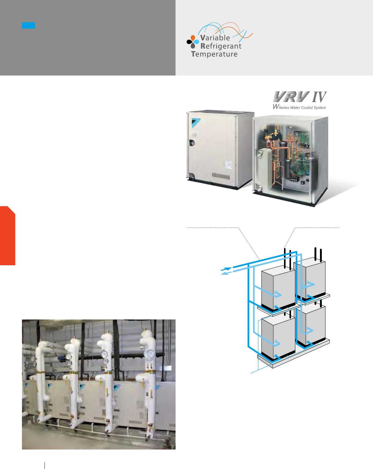
VRV IV W-Series systems are equivalent to 4-pipe chilled water
systems, but also offer a viable alternative to Water Source Heat
Pump solutions. Each connected indoor unit can provide heating
and cooling independently to suit zone requirements making
these systems suitable for both open plan, or cellular applications
with different operation requirements.
Features and Benefits
Reliability, comfort and efficiency working together hand-
in-hand - All VRV IV W-Series incorporate Daikin’s unique
“variable speed” scroll compressor at the heart of the system.
This provides the exact capacity where and when it is
needed, along with outstanding reliability and high part-load
operational efficiency.
Compact and lightweight
-
Compact lightweight casing
-
Height: 39-3/8",
-
Weight: 330 lbs.
-
Install in a mechanical room, double-decker style if needed.
Increased efficiency with Variable Refrigerant
Temperature (VRT) Control
Wide water temperature opera on range - Can be applied
to both geothermal and boiler/tower applications as standard
with condenser water inlet temperature as low as 14°F in
heating and 27°F in cooling is possible.
NEW
VRV IV W-Series
Heat Pump
or Heat Recovery
Need high res
The VRV IV W-Series design is based on a modular design
concept. It is composed of unified condensing units that require
simply connecting a two-pipe refrigerant network for heat
pump applications or a three-pipe refrigerant network for heat
recovery applications. All water-cooled condensers are of the
same dimensions, and are available in 6 tons and 7 tons. This
is a simple system that allows manifolding together up to three
condensers to form one system of up to 21 tons (252 MBH). The
condensers are designed for internal mounting only.
Water side
Connects to cooling tower
and/or boiler combination or
set up as geothermal.
Refrigerant side
Connects to Daikin’s
line-up of VRV indoor
units
The condensers are smaller
and can be stacked, reducing
the installation space and
increasing the customers'
usable square footage.
www.daikincomfort.com86
OUTDOOR UNITS
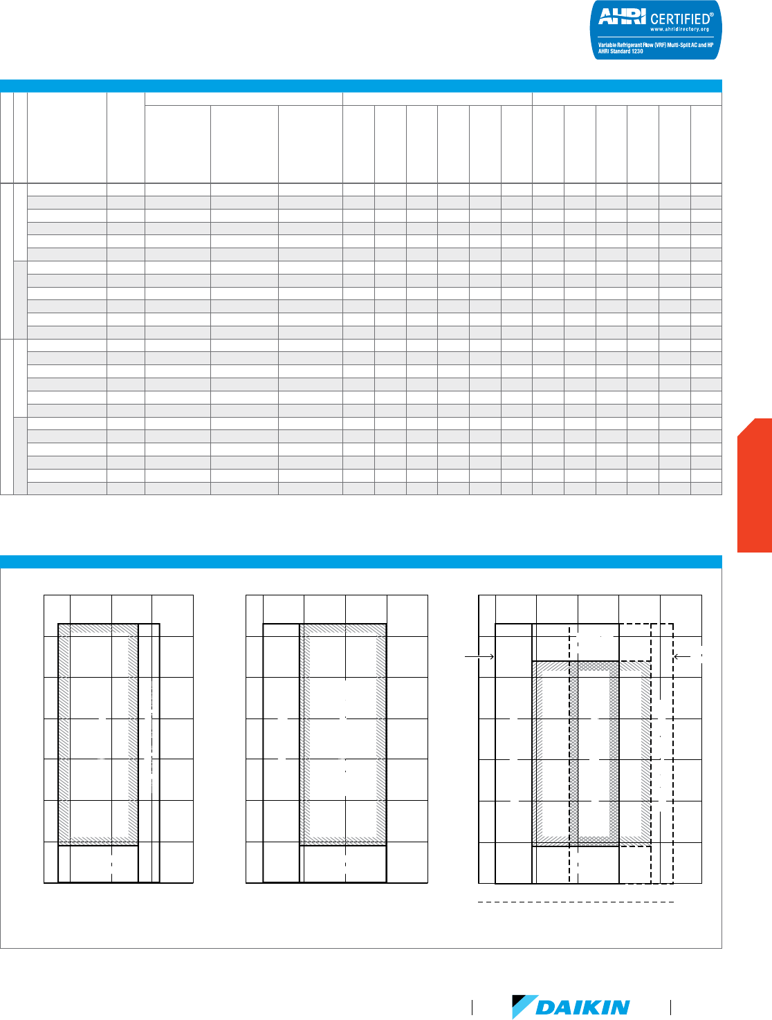
VRV-IV W-SERIES CERTIFIED DATA
System Type
Function
System Name
Tonnage
Condensing Unit Models Part Load Full Load
Unit 1
Unit 2
Unit 3
IEER Non-Ducted
IEER Ducted
IEER Mixed
SCHE Non-Ducted
SCHE Ducted
SCHE Mixed
IEER Non-Ducted
IEER Ducted
IEER Mixed
COP @ 68°F
Non-Ducted
COP @ 68°F
Ducted
COP @ 68°F Mixed
VRV IV W-Series 460V
Heat Pump
RWEYQ72PCYD 6 Tons RWEYQ72PCYD 24.1 22.3 23.2 14.0 14.0 14.0 4.89 4.78 4.89
RWEYQ84PCYD 7 Tons RWEYQ84PCYD 22.5 21.3 21.9 13.4 13.2 13.3 4.70 4.50 4.60
RWEYQ144PCYD 12 Tons RWEYQ72PCYD RWEYQ72PCYD 23.7 22.3 23.0 14.6 14.4 14.5 4.97 4.97 4.97
RWEYQ168PCYD 14 Tons RWEYQ84PCYD RWEYQ84PCYD 23.1 21.3 22.2 12.7 12.7 12.7 4.38 4.38 4.38
RWEYQ216PCYD 18 Tons RWEYQ72PCYD RWEYQ72PCYD RWEYQ72PCYD 22.7 22.2 22.5 14.5 14.5 14.5 4.80 4.91 4.86
RWEYQ252PCYD 21 Tons RWEYQ84PCYD RWEYQ84PCYD RWEYQ84PCYD 21.5 20.0 20.8 12.8 12.8 12.8 4.48 4.48 4.48
Heat Recovery
RWEYQ72PCYD 6 Tons RWEYQ72PCYD 24.1 22.3 23.2 17.8 19.2 18.5 14.0 14.0 14.0 4.89 4.78
RWEYQ84PCYD 7 Tons RWEYQ84PCYD 22.5 21.3 21.9 17.0 17.7 17.3 13.4 13.2 13.3 4.70 4.50
RWEYQ144PCYD 12 Tons RWEYQ72PCYD RWEYQ72PCYD 23.7 22.3 23.0 17.7 19.3 18.5 14.6 14.4 14.5 4.97 4.97
RWEYQ168PCYD 14 Tons RWEYQ84PCYD RWEYQ84PCYD 23.1 21.3 22.2 17.0 17.8 17.4 12.7 12.7 12.7 4.38 4.38
RWEYQ216PCYD 18 Tons RWEYQ72PCYD RWEYQ72PCYD RWEYQ72PCYD 22.2 20.9 21.5 17.8 17.4 17.6 13.3 13.4 13.3 4.80 4.91
RWEYQ252PCYD 21 Tons RWEYQ84PCYD RWEYQ84PCYD RWEYQ84PCYD 21.0 19.3 20.1 15.6 15.8 15.7 12.8 12.4 12.6 4.48 4.48
VRV IV W-Series 208/230V
Heat Pump
RWEYQ72PCTJ 6 Tons RWEYQ72PCTJ 24.1 22.3 23.2 14.0 14.0 14.0 4.89 4.78
RWEYQ84PCTJ 7 Tons RWEYQ84PCTJ 22.5 21.3 21.9 13.4 13.2 13.3 4.70 4.50 4.60
RWEYQ144PCTJ 12 Tons RWEYQ72PCTJ RWEYQ72PCTJ 23.7 22.3 23.0 14.6 14.4 14.5 4.97 4.97 4.97
RWEYQ168PCTJ 14 Tons RWEYQ84PCTJ RWEYQ84PCTJ 23.1 21.3 22.2 12.7 12.7 12.7 4.38 4.38 4.38
RWEYQ216PCTJ 18 Tons RWEYQ72PCTJ RWEYQ72PCTJ RWEYQ72PCTJ 22.2 20.9 21.5 13.3 13.4 13.3 4.80 4.91 4.86
RWEYQ252PCTJ 21 Tons RWEYQ84PCTJ RWEYQ84PCTJ RWEYQ84PCTJ 21.0 19.3 20.1 12.8 12.4 12.6 4.48 4.48 4.48
Heat Recovery
RWEYQ72PCTJ 6 Tons RWEYQ72PCTJ 24.1 22.3 23.2 17.8 19.2 18.5 14.0 14.0 14.0 4.89 4.78
RWEYQ84PCTJ 7 Tons RWEYQ84PCTJ 22.5 21.3 21.9 17.0 17.7 17.3 13.4 13.2 13.3 4.70 4.50
RWEYQ144PCTJ 12 Tons RWEYQ72PCTJ RWEYQ72PCTJ 23.7 22.3 23.0 17.7 19.3 18.5 14.6 14.4 14.5 4.97 4.97
RWEYQ168PCTJ 14 Tons RWEYQ84PCTJ RWEYQ84PCTJ 23.1 21.3 22.2 17.0 17.8 17.4 12.7 12.7 12.7 4.38 4.38
RWEYQ216PCTJ 18 Tons RWEYQ72PCTJ RWEYQ72PCTJ RWEYQ72PCTJ 22.2 20.9 21.5 17.8 17.4 17.6 13.3 13.4 13.3 4.80 4.91
RWEYQ252PCTJ 21 Tons RWEYQ84PCTJ RWEYQ84PCTJ RWEYQ84PCTJ 21.0 19.3 20.1 15.6 15.8 15.7 12.8 12.4 12.6 4.48 4.48
Certified efficiency data in accordance with ANSI/AHRI Standard 1230 2010, “Performance Rating of Variable Refrigerant Flow (VRF) Multi-Split Air Conditioning and Heat Pump Equipment” for the VRV IV W-Series.
The VRV IV W-Series has been designed and optimized to meet or exceed the latest minimum efficiency requirements in 10 C.F.R. Part 431 as determined by the U.S. Department of Energy (DOE) and baseline efficiencies
as defined by ASHRAE 90.1 2010. Systems under 65MBH are currently certified to AHRI 210/240. IEER ratings are as defined in ASHRAE 90.1 2010.
DETAILED STANDARD OPERATION RANGES FOR VRV IV W-SERIES CONDENSING UNITS
See the Engineering Data book for complete application rules
60 70 80 90
Indoor temperature (˚F WB)
110
120
100
90
Cooling
Inlet water temperature (˚F)
80
70
60
50
Range for pull-down operationRange for pull-down operation
Range for continuous operation
Range for continuous operation
Range for
operation
Range for
operation
6050 70 80 90
Indoor temperature (˚F DB)
110
120
100
90
Heating
Inlet water temperature (˚F)
80
70
60
50
Range for warming up operation Range for warming up operation
Range for
operation
Range for
operation
Range for continuous operation Range for continuous operation
50 59 80 (Heating unit / ˚F DB)
Cooling & Heating
Inlet water temperature (˚F)
120
100
90
80
70
60
50
Indoor temperature
57 77 82
(Cooling unit / ˚F WB)
110
Range for
operation
Range for
operation
Range for continuous operation Range for continuous operation
Range for warming up operation
Range for warming up operation
Range for pull-down operation
Range for pull-down operation
Range for
operation
Range for
operation
Heating
Range
Cooling
Range
Cooling
Range
VRV Product Catalog
87
OUTDOOR UNITS
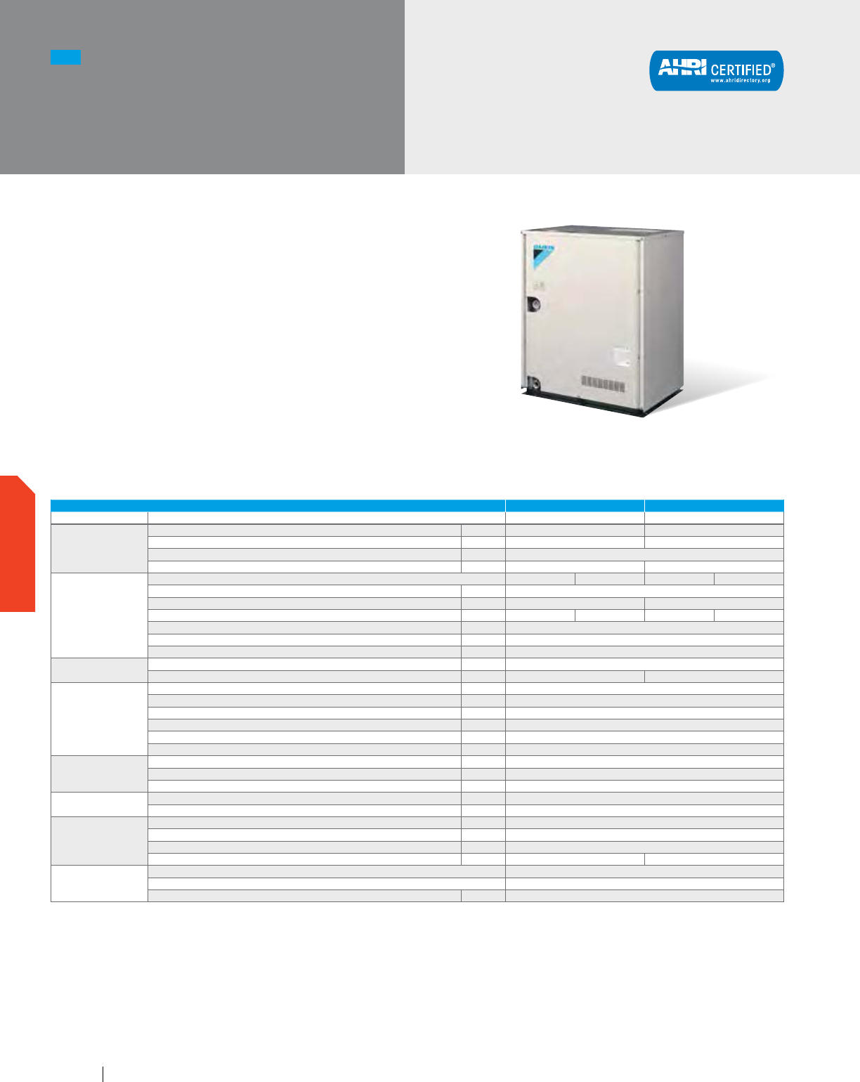
¹ Indoor temp.: 80°FDB, 67°FWB/inlet water temp.: 85°F/
Equivalent piping length : 25 ft., level difference : 0 ft.
² Indoor temp.: 70°FDB, 60°FWB/inlet water temp.: 70°F/
Equivalent piping length: 25 ft., level difference : 0 ft.
3
Please note that a water strainer is required for each condensing
unit model and now must be field supplied (strainer specification =
50 mesh).
4
Application rules apply below 48°F. Please contact your local
Daikin office for design assistance and approval.
5
The minimum cooling EWT is 34°F when the condensing unit is
located below the indoor units.
NEW
VRV IV W-Series
Single Module System
208-230V
RWEYQ-PCTJ
A modular, energy-saving and reliable
alternative to centralized equipment.
Features and Benefits
Compact lightweight casing at 39-3/8"
in height and 330 lbs. in weight
Small condensers can be stacked for reduced installation space
and increased usable square footage
Larger single-system capacity and modular concept ensures
wider application range for accommodating floor-by-floor loads
of commercial buildings
Can be applied to both geothermal and boiler/tower applications
as standard with condenser water inlet temperature as low as
14°F in heating and 27°F in cooling is possible
VRV IV W-SERIES UNIFIED HEAT PUMP AND HEAT RECOVERY 6 TON 7 TON
Model Name RWEYQ72PCTJ RWEYQ84PCTJ
Performance
Rated Cooling Capacity ¹ BTU/h 64,000 80,000
Rated Heating Capacity ² BTU/h 77,000 90,000
Power V/ph/Hz 208-230/3/60
Sound Pressure Level @ 3 ft. dB(A) 50 51
Refrigerant Piping
System Configuration Heat Pump Heat Recovery Heat Pump Heat Recovery
Liquid Pipe (Main Line) in. 3/8
Suction Gas Pipe (Main Line) in. 3/4 7/8
Discharge Gas Pipe (Main Line) in. N/A 5/8 N/A 3/4
Vertical Pipe Length (if unit is below FCU) ft. 164 (130)
Actual Pipe Length (Equivalent Length) ft. 390 (459)
Total Pipe Length ft. 980
Connection Ratio
Standard Connectable Indoor Unit Ratio % 50 - 130
Maximum Number of Indoor Units Qty. 12 14
Water Side
(Standard)
BPHE Inlet Pipe (Female Thread) in. 1-1/4 FPT
BPHE Outlet Pipe (Female Thread) in. 1-1/4 FPT
Drain Pipe (Female Thread) in. 1/2 FPS
Maximum System Water Pressure (BPHE) psi 285
Standard Inlet Water Temperature Range °F 50 - 113
Recommended Inlet Water Flow Rate per Module (minimum)
3
gpm 16.4 ~ 39.5 (13.2)
Water Side
(Geothermal)
Inlet Water Temperature Range Cooling
4
°F 27 (34
5
) - 113
Inlet Water Temperature Range Heating °F 14 - 113
Water Flow Rate gpm 21 - 40
Unit
Weight lbs. 330
Dimensions (H x W x D) in. 39-3/8 x 30-3/4 x 21-11/16
Electrical
Voltage Range (min - max) V/ph/Hz 187 - 253
Maximum Overcurrent Protection (MOP) A 30
Minimum Circuit Amps (MCA) A 22.4
Compressor Rated Load Amps (RLA) A 11.6 15.4
Compressor
Compressor Type Daikin G-Type Scroll
Compressor Set-Up 1 INV
Compressor Capacity Control % 23 - 100
www.daikincomfort.com88
OUTDOOR UNITS
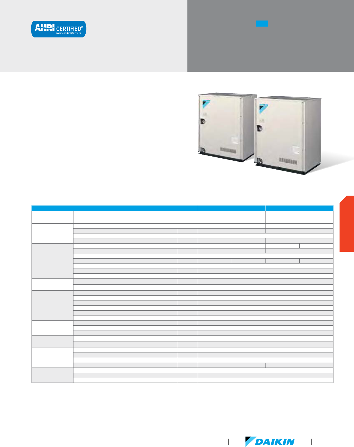
A modular, energy-saving and reliable
alternative to centralized equipment.
Features and Benefits
Compact lightweight casing at 39-3/8"
in height and 330 lbs. in weight per module
Small condensers can be stacked for reduced installation space
and increased usable square footage
Larger single-system capacity and modular concept ensures
wider application range for accommodating floor-by-floor loads
of commercial buildings
Can be applied to both geothermal and boiler/tower applications
as standard with condenser water inlet temperature as low as
14°F in heating and 27°F in cooling is possible
NEW
VRV IV W-Series
Double Module System
208-230V
RWEYQ-PCTJ
VRV IV W-SERIES UNIFIED HEAT PUMP AND HEAT RECOVERY 12 TON 14 TON
Model
Name RWEYQ144PCTJ RWEYQ168PCTJ
Combination 2 x RWEYQ72PCTJ 2 x RWEYQ84PCTJ
Performance
Rated Cooling Capacity ¹ BTU/h 138,000 160,000
Rated Heating Capacity ² BTU/h 154,000 180,000
Power V/ph/Hz 208-230/3/60
Sound Pressure Level @ 3 ft. dB(A) 53 54
Refrigerant Piping
System Configuration Heat Pump Heat Recovery Heat Pump Heat Recovery
Liquid Pipe (Main Line) in. 1/2 5/8
Suction Gas Pipe (Main Line) in. 1-1/8
Discharge Gas Pipe (Main Line) in. N/A 7/8 N/A 7/8
Vertical Pipe Length (if unit is below FCU) ft. 164 (130)
Actual Pipe Length (Equivalent Length) ft. 390 (459)
Total Pipe Length ft. 980
Connection Ratio
Standard Connectable Indoor Unit Ratio % 50 - 130
Maximum Number of Indoor Units Qty. 20
Water Side
(Standard)
B
PHE Inlet Pipe (Female Thread) in. 2 x (1-1/4 FPT)
BPHE Outlet Pipe (Female Thread) in. 2 x (1-1/4 FPT)
Drain Pipe (Female Thread) in. 2 x (1/2 FPS)
Maximum System Water Pressure (BPHE) psi 285
Standard Inlet Water Temperature Range °F 50 - 113
Recommended Inlet Water Flow Rate per Module (minimum)
3
gpm 16.4 ~ 39.5 (13.2)
Water Side
(Geothermal)
Inlet Water Temperature Range Cooling
4
°F 27 (34
5
) - 113
Inlet Water Temperature Range Heating °F 14 - 113
Water Flow Rate gpm 21 - 40
Unit
Weight lbs. 2 x 330
Dimensions (H x W x D) in. 39-3/8 x (30-3/4 x 2) x 21-11/16
Electrical
Voltage Range (min - max) V/ph/Hz 187 - 253
Maximum Overcurrent Protection (MOP) A 30 + 30
Minimum Circuit Amps (MCA) A 22.4 + 22.4
Compressor Rated Load Amps (RLA) A 11.6 + 11.6 15.4 + 15.4
Compressor
Compressor Type Daikin G-Type Scroll
Compressor Set-Up 1 INV + 1 INV
Compressor Capacity Control % 11 - 100
¹ Indoor temp.: 80°FDB, 67°FWB/inlet water temp.: 85°F/
Equivalent piping length : 25 ft., level difference : 0 ft.
² Indoor temp.: 70°FDB, 60°FWB/inlet water temp.: 70°F/
Equivalent piping length: 25 ft., level difference : 0 ft.
3
Please note that a water strainer is required for each condensing
unit model and now must be field supplied (strainer specification =
50 mesh).
4
Application rules apply below 48°F. Please contact your local Daikin
office for design assistance and approval.
5
The minimum cooling EWT is 34°F when the condensing unit is
located below the indoor units.
VRV Product Catalog
89
OUTDOOR UNITS
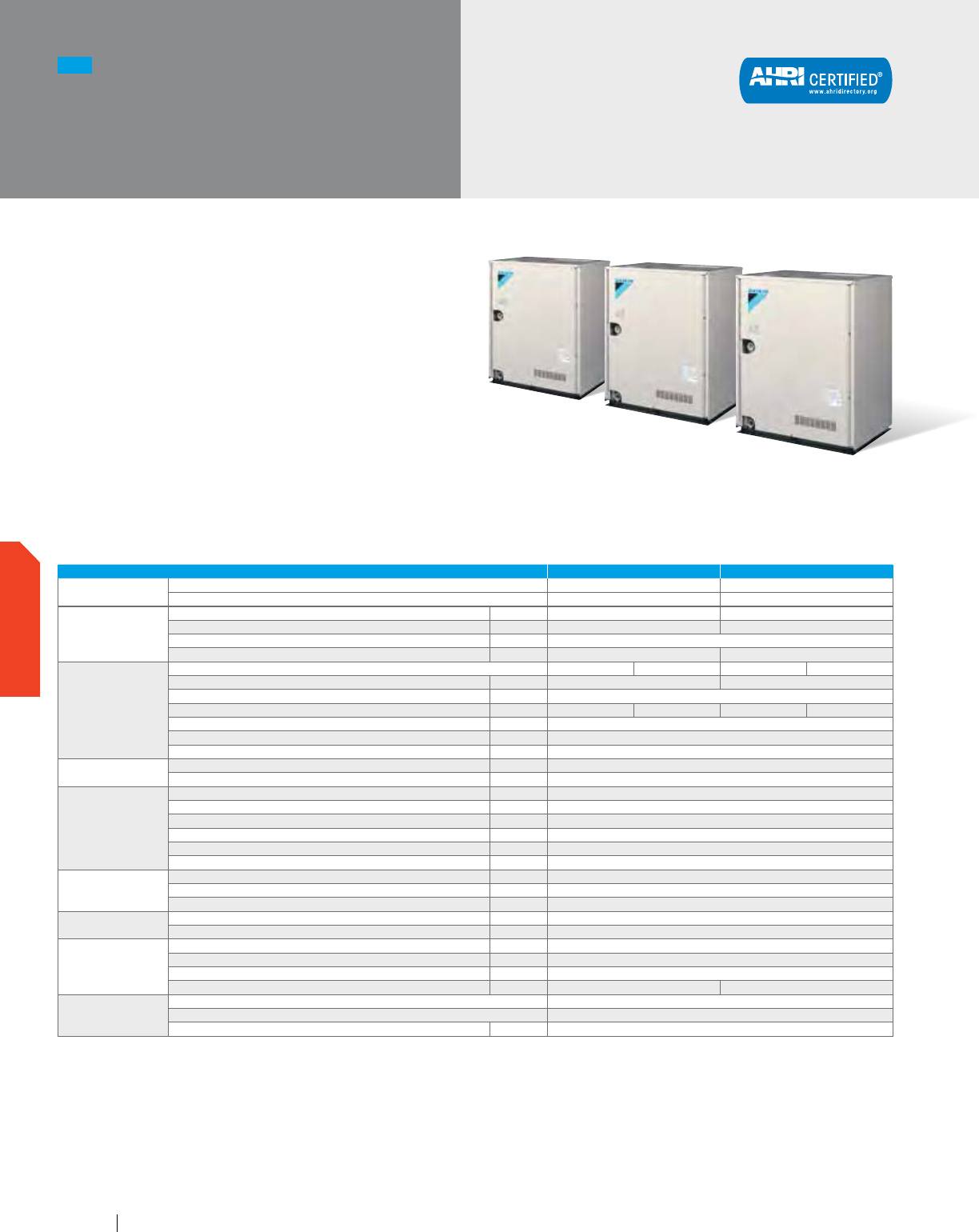
NEW
VRV IV W-Series
Triple Module System
208-230V
RWEYQ-PCTJ
A modular, energy-saving and reliable
alternative to centralized equipment.
Features and Benefits
Compact lightweight casing at 39-3/8"
in height and 330 lbs. in weight per module
Small condensers can be stacked for reduced installation
space and increased usable square footage
Larger single-system capacity and modular concept
ensures wider application range for accommodating
floor-by-floor loads of commercial buildings
Standard VRV IV W-Series systems can operate
with condenser water temperatures down to 50°F
but this can be extended to 14°F in heating
¹ Indoor temp.: 80°FDB, 67°FWB/inlet water temp.: 85°F/
Equivalent piping length: 25 ft., level difference: 0 ft.
² Indoor temp.: 70°FDB, 60°FWB/inlet water temp.: 70°F/
Equivalent piping length: 25 ft., level difference: 0 ft.
3
Please note that a water strainer is required for each condensing
unit model and now must be field supplied (strainer specification
= 50 mesh).
4
Application rules apply below 48°F. Please contact your local
Daikin office for design assistance and approval.
5
The minimum cooling EWT is 34°F when the condensing unit is
located below the indoor units.
VRV IV W-SERIES UNIFIED HEAT PUMP AND HEAT RECOVERY 18 TON 21 TON
Model
Name RWEYQ216PCTJ RWEYQ252PCTJ
Combination 3 x RWEYQ72PCTJ 3 x RWEYQ84PCTJ
Performance
Rated Cooling Capacity¹ BTU/h 206,000 240,000
Rated Heating Capacity² BTU/h 232,000 270,500
Power V/ph/Hz 208-230/3/60
Sound Pressure Level @ 3 ft. dB(A) 56 57
Refrigerant Piping
System Configuration Heat Pump Heat Recovery Heat Pump Heat Recovery
Liquid Pipe (Main Line) in. 5/8 3/4
Suction Gas Pipe (Main Line) in. 1-3/8
Discharge Gas Pipe (Main Line) in. N/A 1-1/8 N/A 1-1/8
Vertical Pipe Length (if unit is below FCU) ft. 164 (130)
Actual Pipe Length (Equivalent Length) ft. 390 (459)
Total Pipe Length ft. 980
Connection Ratio
Standard Connectable Indoor Unit Ratio % 50 - 130
Maximum Number of Indoor Units Qty. 22
Water Side
(Standard)
BPHE Inlet Pipe (Female Thread) in. 3 x (1-1/4 FPT)
BPHE Outlet Pipe (Female Thread) in. 3 x (1-1/4 FPT)
Drain Pipe (Female Thread) in. 3 x (1/2 FPS)
Maximum System Water Pressure (BPHE) psi 285
Standard Inlet Water Temperature Range °F 50 - 113
Recommended Inlet Water Flow Rate per Module (minimum)
3
gpm 16.4 ~ 39.5 (13.2)
Water Side
(Geothermal)
Inlet Water Temperature Range Cooling
4
°F 27 (34
5
) - 113
Inlet Water Temperature Range Heating °F 14 - 113
Water Flow Rate gpm 21 - 40
Unit
Weight lbs. 3 x 330
Dimensions (H x W x D) in. 39-3/8 x (30-3/4 x 3) x 21-11/16
Electrical
Voltage Range (min - max) V/ph/Hz 187 - 253
Maximum Overcurrent Protection (MOP) A 30 + 30 + 30
Minimum Circuit Amps (MCA) A 22.4 + 22.4 + 22.4
Compressor Rated Load Amps (RLA) A 11.6 + 11.6 + 11.6 15.4 + 15.4 + 15.4
Compressor
Compressor Type Daikin G-Type Scroll
Compressor Set-Up 1 INV + 1 INV + 1 INV
Compressor Capacity Control % 8 - 100
www.daikincomfort.com90
OUTDOOR UNITS
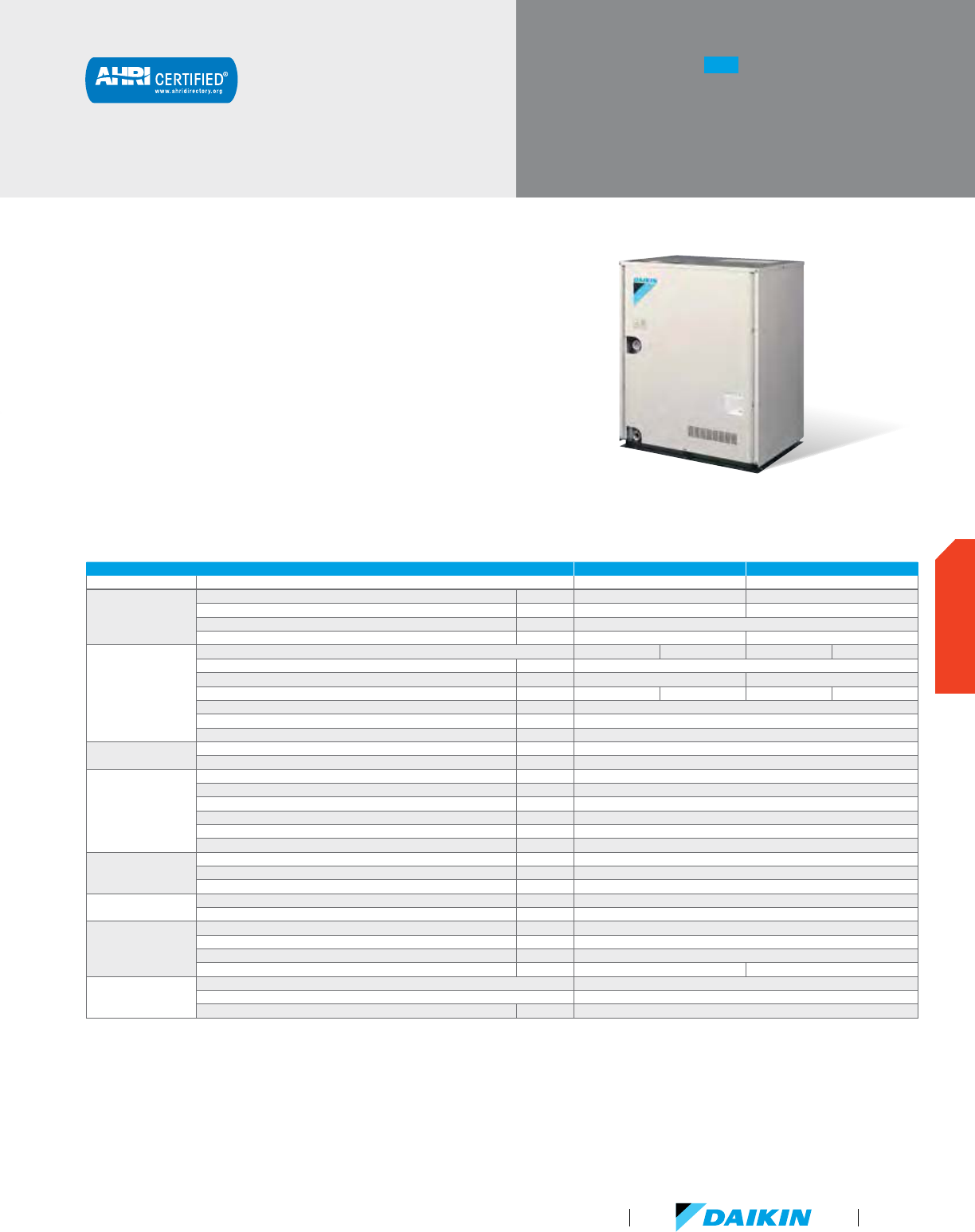
NEW
VRV IV W-Series
Single Module System
460V
A modular, energy-saving and reliable
alternative to centralized equipment.
Features and Benefits
Compact lightweight casing at 39-3/8"
in height and 343 lbs. in weight
Small condensers can be stacked for reduced installation
space and increased usable square footage
Larger single-system capacity and modular concept
ensures wider application range for accommodating
floor-by-floor loads of commercial buildings
Standard VRV IV W-Series systems can operate
with condenser water temperatures down to 50°F
but this can be extended to 14°F in heating
RWEYQ-PCYD
VRV IV W-SERIES UNIFIED HEAT PUMP AND HEAT RECOVERY 6 TONS 7 TONS
Model Name RWEYQ72PCYD RWEYQ84PCYD
Performance
Rated Cooling Capacity¹ BTU/h 69,000 80,000
Rated Heating Capacity² BTU/h 77,000 90,000
Power V/ph/Hz 460/3/60
Sound Pressure Level @ 3 ft. dB(A) 50 51
Refrigerant Piping
System Configuration Heat Pump Heat Recovery Heat Pump Heat Recovery
Liquid Pipe (Main Line) in. 3/8
Suction Gas Pipe (Main Line) in. 3/4 7/8
Discharge Gas Pipe (Main Line) in. N/A 5/8 N/A 3/4
Vertical Pipe Length (if unit is below FCU) ft. 164 (130)
Actual Pipe Length (Equivalent Length) ft. 390 (459)
Total Pipe Length ft. 980
Connection Ratio
Standard Connectable Indoor Unit Ratio % 50 - 130
Maximum Number of Indoor Units Qty. 12
Water Side
(Standard)
BPHE Inlet Pipe (Female Thread) in. 1-1/4 FPT
BPHE Outlet Pipe (Female Thread) in. 1-1/4 FPT
Drain Pipe (Female Thread) in. 1/2 FPS
Maximum System Water Pressure (BPHE) psi 285
Standard Inlet Water Temperature Range °F 50 - 113
Recommended Inlet Water Flow Rate per Module (minimum)
3
gpm 16.4 ~ 39.5 (13.2)
Water Side
(Geothermal)
Inlet Water Temperature Range Cooling
4
°F 27 (34
5
) - 113
Inlet Water Temperature Range Heating °F 14 - 113
Water Flow Rate gpm 21 - 40
Unit
Weight lbs. 343
Dimensions (H x W x D) in. 39-3/8 x 30-3/4 x 21-11/16
Electrical
Voltage Range (min - max) V/ph/Hz 414 - 506
Maximum Overcurrent Protection (MOP) A 15
Minimum Circuit Amps (MCA) A 10.2
Compressor Rated Load Amps (RLA) A 5.3 7.0
Compressor
Compressor Type Daikin G-Type Scroll
Compressor Set-Up 1 INV
Compressor Capacity Control % 23 - 100
¹ Indoor temp.: 80°FDB, 67°FWB/inlet water temp.: 85°F/
Equivalent piping length: 25 ft., level difference: 0 ft.
² Indoor temp.: 70°FDB, 60°FWB/inlet water temp.: 70°F/
Equivalent piping length: 25 ft., level difference: 0 ft.
3
Please note that a water strainer is required for each condensing
unit model and now must be field supplied (strainer specification
= 50 mesh).
4
Application rules apply below 48°F. Please contact your local
Daikin office for design assistance and approval.
5
The minimum cooling EWT is 34°F when the condensing unit is
located below the indoor units.
VRV Product Catalog
91
OUTDOOR UNITS
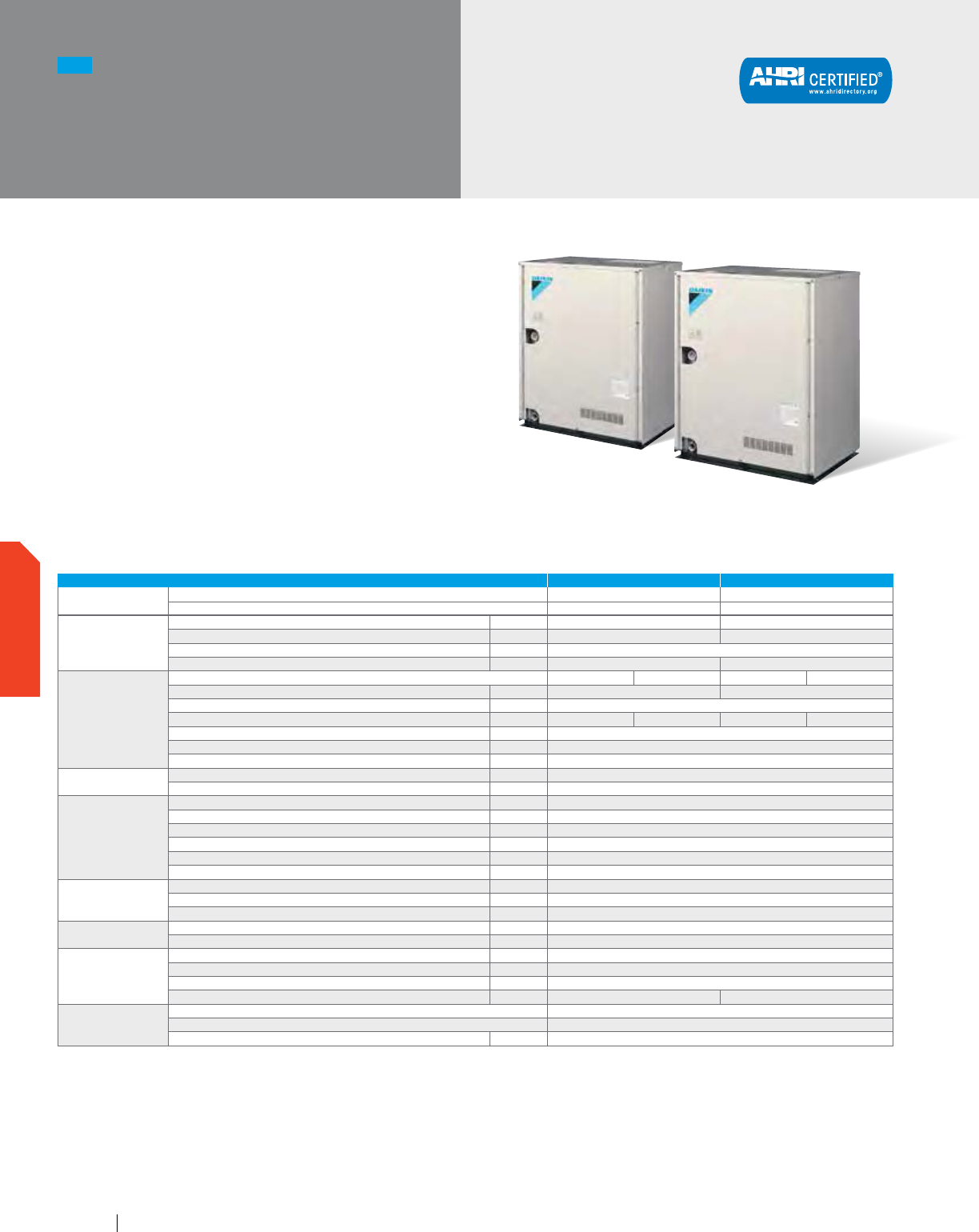
A modular, energy-saving and reliable
alternative to centralized equipment.
Features and Benefits
Compact lightweight casing at 39-3/8"
in height and 343 lbs. in weight per module
Small condensers can be stacked for reduced installation
space and increased usable square footage
Larger single-system capacity and modular concept
ensures wider application range for accommodating
floor-by-floor loads of commercial buildings
Standard VRV IV W-Series systems can operate
with condenser water temperatures down to 50°F
but this can be extended to 14°F in heating
RWEYQ-PCYD
NEW
VRV IV W-Series
Double Module
System 460V
VRV IV W-SERIES UNIFIED HEAT PUMP AND HEAT RECOVERY 12 TON 14 TON
Model
Name RWEYQ144PCYD RWEYQ168PCYD
Combination 2 x RWEYQ72PCYD 2 x RWEYQ84PCYD
Performance
Rated Cooling Capacity¹ BTU/h 138,000 160,000
Rated Heating Capacity² BTU/h 154,000 180,000
Power V/ph/Hz 460/3/60
Sound Pressure Level @ 3 ft. dB(A) 53 54
Refrigerant Piping
System Configuration Heat Pump Heat Recovery Heat Pump Heat Recovery
Liquid Pipe (Main Line) in. 1/2 5/8
Suction Gas Pipe (Main Line) in. 1-1/8
Discharge Gas Pipe (Main Line) in. N/A 7/8 N/A 7/8
Vertical Pipe Length (if unit is below FCU) ft. 164 (130)
Actual Pipe Length (Equivalent Length) ft. 390 (459)
Total Pipe Length ft. 980
Connection Ratio
Standard Connectable Indoor Unit Ratio % 50 - 130
Maximum Number of Indoor Units Qty. 20
Water Side
(Standard)
BPHE Inlet Pipe (Female Thread) in. 2 x (1-1/4 FPT)
BPHE Outlet Pipe (Female Thread) in. 2 x (1-1/4 FPT)
Drain Pipe (Female Thread) in. 2 x (1/2 FPS)
Maximum System Water Pressure (BPHE) psi 285
Standard Inlet Water Temperature Range °F 50 - 113
Recommended Inlet Water Flow Rate per Module (minimum)
3
gpm 16.4 ~ 39.5 (13.2)
Water Side
(Geothermal)
Inlet Water Temperature Range Cooling
4
°F 27 (34
5
) - 113
Inlet Water Temperature Range Heating °F 14 - 113
Water Flow Rate gpm 21 - 40
Unit
Weight lbs. 2 x 343
Dimensions (H x W x D) in. 39-3/8 x (30-3/4 x 2) x 21-11/16
Electrical
Voltage Range (min - max) V/ph/Hz 414 - 506
Maximum Overcurrent Protection (MOP) A 15 + 15
Minimum Circuit Amps (MCA) A 10.2 + 10.2
Compressor Rated Load Amps (RLA) A 5.3 + 5.3 7.0 + 7.0
Compressor
Compressor Type Daikin G-Type Scroll
Compressor Set-Up 1 INV + 1 INV
Compressor Capacity Control % 11 - 100
¹ Indoor temp.: 80°FDB, 67°FWB/inlet water temp.: 85°F/
Equivalent piping length: 25 ft., level difference: 0 ft.
² Indoor temp.: 70°FDB, 60°FWB/inlet water temp.: 70°F/
Equivalent piping length: 25 ft., level difference: 0 ft.
3
Please note that a water strainer is required for each condensing
unit model and now must be field supplied (strainer specification
= 50 mesh).
4
Application rules apply below 48°F. Please contact your local
Daikin office for design assistance and approval.
5
The minimum cooling EWT is 34°F when the condensing unit is
located below the indoor units.
www.daikincomfort.com92
OUTDOOR UNITS
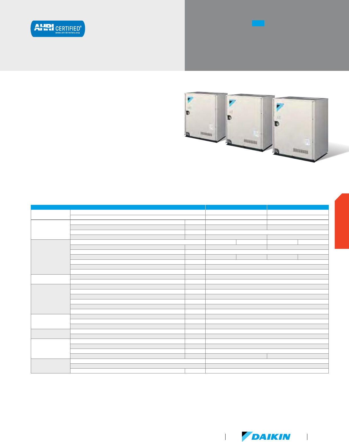
RWEYQ-PCYD
A modular, energy-saving and reliable
alternative to centralized equipment.
Features and Benefits
Compact lightweight casing at 39-3/8"
in height and 343 lbs. in weight per module
Small condensers can be stacked for reduced installation
space and increased usable square footage
Larger single-system capacity and modular concept
ensures wider application range for accommodating
floor-by-floor loads of commercial buildings
Standard VRV IV W-Series systems can operate
with condenser water temperatures down to 50°F
but this can be extended to 14°F in heating
NEW
VRV IV W-Series
Triple Module System
460V
VRV IV W-SERIES UNIFIED HEAT PUMP AND HEAT RECOVERY 18 TONS 21 TONS
Model
Name RWEYQ216PCYD RWEYQ252PCYD
Combination 3 x RWEYQ72PCYD 3 x RWEYQ84PCYD
Performance
Rated Cooling Capacity¹ BTU/h 206,000 240,000
Rated Heating Capacity² BTU/h 232,000 270,500
Power V/ph/Hz 460/3/60
Sound Pressure Level @ 3 ft. dB(A) 56 57
Refrigerant Piping
System Configuration Heat Pump Heat Recovery Heat Pump Heat Recovery
Liquid Pipe (Main Line) in. 5/8 3/4
Suction Gas Pipe (Main Line) in. 1-3/4
Discharge Gas Pipe (Main Line) in. N/A 1-1/8 N/A 1-1/8
Vertical Pipe Length (if unit is below FCU) ft. 164 (130)
Actual Pipe Length (Equivalent Length) ft. 390 (459)
Total Pipe Length ft. 980
Connection Ratio
Standard Connectable Indoor Unit Ratio % 50 - 130
Maximum Number of Indoor Units Qty. 22
Water Side
(Standard)
BPHE Inlet Pipe (Female Thread) in. 3 x (1-1/4 FPT)
BPHE Outlet Pipe (Female Thread) in. 3 x (1-1/4 FPT)
Drain Pipe (Female Thread) in. 3 x (1/2 FPS)
Maximum System Water Pressure (BPHE) psi 285
Standard Inlet Water Temperature Range °F 50 - 113
Recommended Inlet Water Flow Rate per Module (minimum)
3
gpm 16.4 ~ 39.5 (13.2)
Water Side
(Geothermal)
Inlet Water Temperature Range Cooling
4
°F 27 (34
5
) - 113
Inlet Water Temperature Range Heating °F 14 - 113
Water Flow Rate gpm 21 - 40
Unit
Weight lbs. 3 x 343
Dimensions (H x W x D) in. 39-3/8 x (30-3/4 x 3) x 21-11/16
Electrical
Voltage Range (min - max) V/ph/Hz 414 - 506
Maximum Overcurrent Protection (MOP) A 15 + 15 + 15
Minimum Circuit Amps (MCA) A 10.2 + 10.2 + 10.2
Compressor Rated Load Amps (RLA) A 5.3 + 5.3 + 5.3 7.0 + 7.0 + 7.0
Compressor
Compressor Type Daikin G-Type Scroll
Compressor Set-Up 1 INV + 1 INV + 1 INV
Compressor Capacity Control % 8 - 100
¹ Indoor temp.: 80°FDB, 67°FWB/inlet water temp.: 85°F/
Equivalent piping length: 25 ft., level difference: 0 ft.
² Indoor temp.: 70°FDB, 60°FWB/inlet water temp.: 70°F/
Equivalent piping length: 25 ft., level difference: 0 ft.
3
Please note that a water strainer is required for each condensing
unit model and now must be field supplied (strainer specification
= 50 mesh).
4
Application rules apply below 48°F. Please contact your local
Daikin office for design assistance and approval.
5
The minimum cooling EWT is 34°F when the condensing unit is
located below the indoor units.
VRV Product Catalog
93
OUTDOOR UNITS
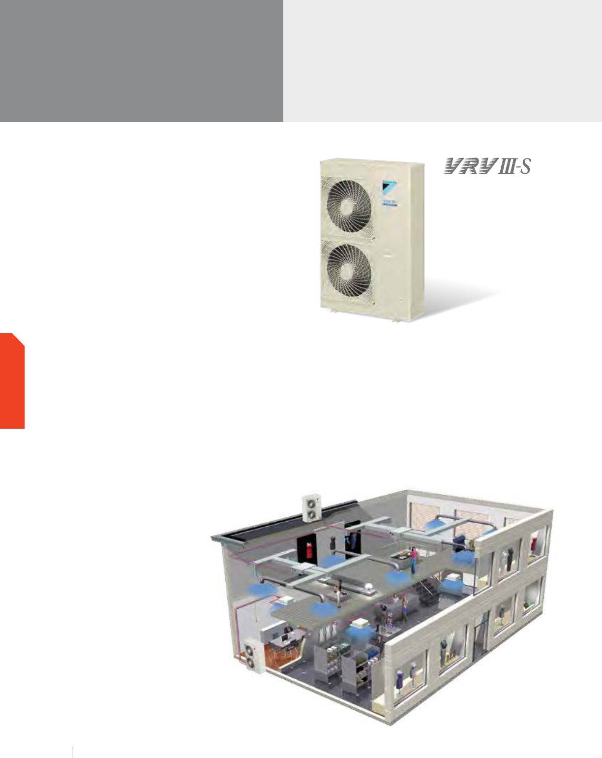
VRV III-S
Heat Pump
208-230V
VRV III-S systems are equipped with built-in intelligence which
provide independent zoning control to help maximize flexibility
and energy savings. With the ability to connect up to eight indoor
units to one outdoor unit, the space saving VRV III-S system
is ideal for most light commercial and residential applications.
Light Commercial
A highly efficient solution for small commercial applications, the
VRV III-S provides cooling and heating for up to 8 zones. With
many different indoor unit options to choose from, systems can
be paired with a mix of ducted and duct-free indoor units for a
customizable system for almost any application.
Designed for flexibility and versatility, the VRV III-S system
provides long piping lengths (up to 1000 ft. actual piping length
one way), making it an accommodating and space-saving solution
for almost any floor layout.
Features and Benefits
Single phase technology
Smaller capacity for precise temperature control
Space saving design and flexible indoor unit
option offer quick and easy installation
Superior energy efficiency, especially
under part load conditions
Soft sound levels for comfort
Single supplier reliability
Straightforward maintenance and
service with self-diagnostic functions
Residential
VRV III-S provides an intelligent alternative for both renovated
and new construction homes. Connecting up to eight zones on
a single outdoor unit, this system provides design flexibility in a
compact, space-saving design.
Indoor units offer speed control with quiet operating sound
levels as low as 28 dB(A) with outdoor units having built-in
noise reducing features. Activate the night set mode feature
and operating sounds progressively reduce 3 B(A) for quieter
and gentler cooler or heating.
www.daikincomfort.com
94
OUTDOOR UNITS
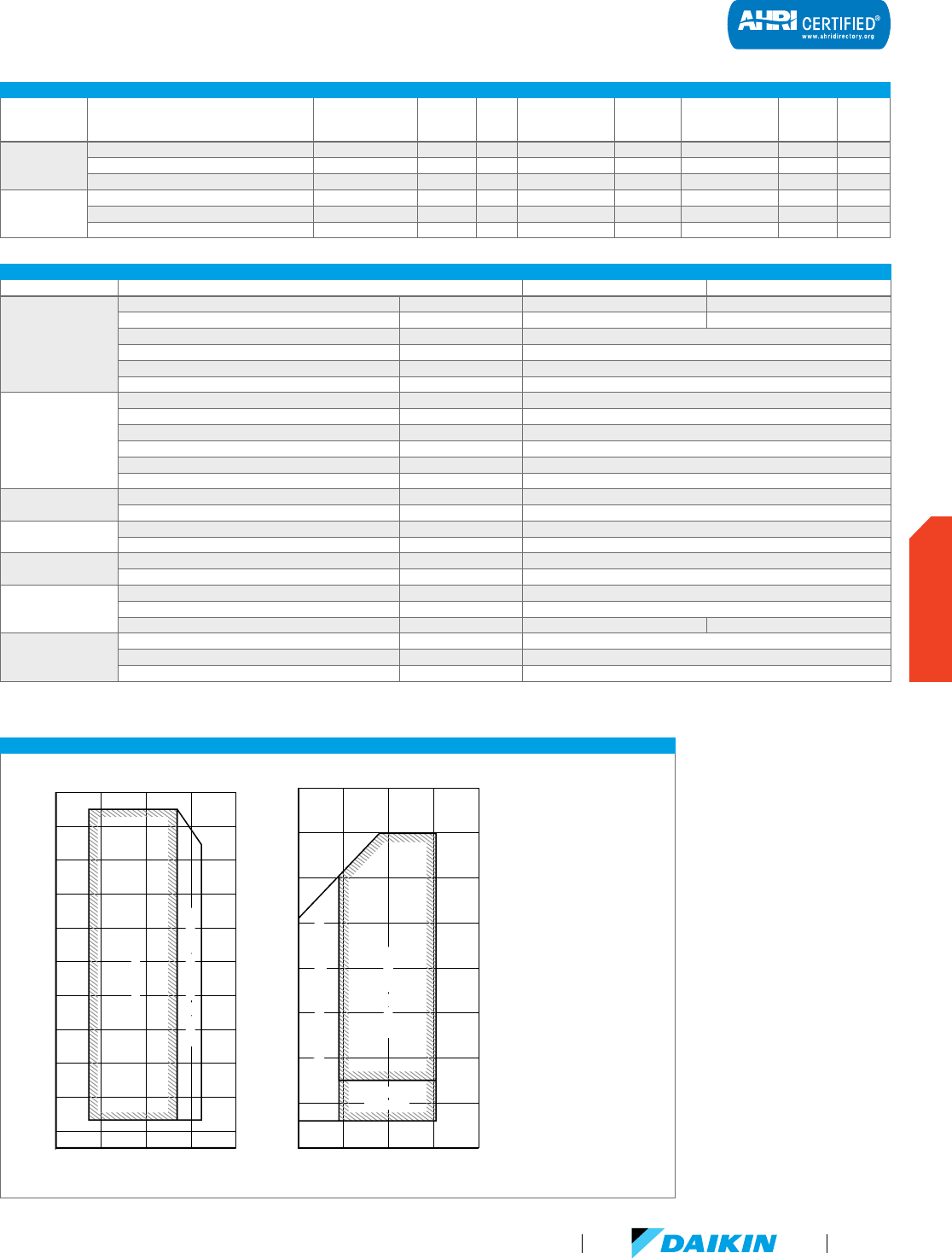
VRV III-S 208-230V HEAT PUMP
Model Name RXYMQ36PVJU RXYMQ48PVJU
Performance
Rated Cooling Capacity BTU/h 36,000 47,500
Rated Heating Capacity BTU/hw 42,000 52,500
Operating Range - Cooling °F DB 23 - 115
Operating Range - Heating °F DB/°F WB 0 - 64 / -5 - 60
Power V/ph/Hz 208-230/1/60
Sound Pressure Level @ 3 ft. dB(A) 58
Refrigerant Piping
Refrigerant Type and Quantity (lbs.) R-410A (8.8)
Liquid Pipe (Main Line) in. 3/8 (Flare)
Suction Gas Pipe (Main Line) in. 5/8 (Flare)
Vertical Pipe Length ft. 164
Actual Pipe Length (Equivalent Length) ft. 492
Total Piping Length ft. 984
Connection Ratio
Connectable Indoor Unit Ratio % 50 - 130%
Number of Indoor Units Qty. 6
Unit
Weight lbs. 283
Dimensions (H x W x D) in. 52-15/16 x 35-7/16 x 12-5/8
Fan
Airflow CFM 3,740
Fan Motor Output and Quantity kW (Qty.) 0.07 (2)
Electrical
Maximum Overcurrent Protection (MOP) A 30.0
Minimum Circuit Amps (MCA) A 2 7.0
Compressor Rated Load Amps (RLA) A 17.6 23.3
Compressor
Compressor Type Daikin G-Type Scroll
Compressor Set-Up 1 INV
Compressor Capacity Control % 29 - 100
DETAILED OPERATION RANGES FOR VRV III-S (RXYMQ-PVJU) HEAT PUMP OUTDOOR UNITS
50 60 70 80 90 50 60 70 80 90
Indoor temperature (˚F WB)Indoor temperature (˚F DB)
Cooling
Heating
Outdoor temperature (˚F DB)
Outdoor temperature (˚F WB)
Range for warming up operation
Range for warming up operation
110
120
100
90
20
15
80
70
60
50
40
30
Range for operation Range for operation
Range for operation
Range for operation
Range for pull-down operation
Range for pull-down operation
20
70
60
50
40
30
-10
10
0
Range for
operation
Range for
operation
Note: These figures assume the
following operating conditions.
Indoor and outdoor units:
- Equivalent pipe length: 25 ft
- Level difference: 0 ft.
CERTIFIED PERFORMANCE DATA
Model Number Indoor Units Combination
Nominal Cooling
Capacity (BTU/h)
EER 95F SEER
Nominal Heating
Capacity (BTU/h)
Heating COP
@ 47 °F
Low Heating
Capacity (BTU/h)
H
eating
COP @
17 °F
HSPF
RXYMQ36PVJU
Ducted Indoor Units 36,000 9.9 14 42,000 2.90 29,500 2.10 8.4
Non-Ducted Indoor Units 36,000 11.5 14.9 42,000 2.80 26,000 2.00 8.2
Mixed Ducted and Non-Ducted Indoor Units 36,000 10.7 14.45 42,000 2.85 27,750 2.05 8.3
RXYMQ48PVJU
Ducted Indoor Units 47,500 9 14 52,500 2.70 36,500 2.00 8.8
Non-Ducted Indoor Units 47,500 9 15.1 52,500 2.60 33,000 2.00 9.1
Mixed Ducted and Non-Ducted Indoor Units 47,500 9 14.55 52,500 2.65 34,750 2.00 8.95
VRV Product Catalog
95
OUTDOOR UNITS
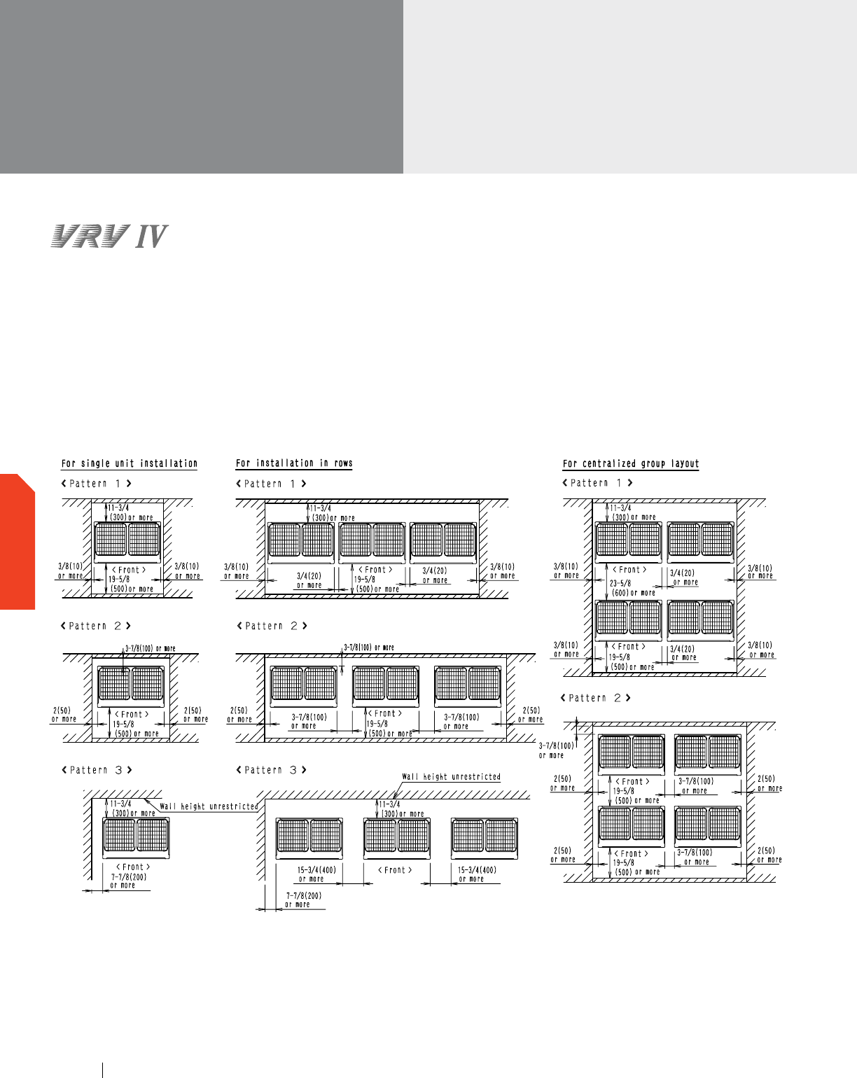
Installation Space Examples
The installation space requirement shown in the figure is a
reference for cooling.
During installation, install the units using the most appropriate
of the patterns shown in the figure for the location in question,
taking into consideration human traffic and wind.
If the number of units installed is more than that shown in
the pattern in the figure, install the units so that there is no
air short circuiting.
Consider the space needed for the refrigerant piping when
installing the units, as determined by local codes.
If the space requirements in the figure do not apply, contact
your contractor or Daikin directly.
VRV IV
Installation Space
NOTE: If more units are to be installed than are shown in Section 3, your layout should take account of the possibility of short
circuiting.
Section 3
www.daikincomfort.com96
OUTDOOR UNITS

NOTE: If more units are to be installed than are shown in Section 3, your layout should take account of the possibility of short
circuiting.
Section 3
Notes
1. Heights of walls in case of Patterns 1 and 2:
Front: 59in
Suction side: 19-5/8in
Side: Height unrestricted.
Installation space shown in this drawing is based on the
cooling operation at 95°F outdoor air temperature.
When the design outdoor temperature exceeds 95°F or the
load exceeds maximum ability because of much generation
load of heat in all outdoor unit, take the suction-side space
more broadly than the space shown in this drawing.
2. If the above wall heights are exceeded then h2/2 and
h1/2 should be added to the front and suction side
service spaces respectively as shown in the figure.
3. When installing, the units
most appropriate pattern
should be selected in
order to obtain the best
fit in the space available,
always bearing in mind
the need to leave enough
space for a person
to pass between the
units and wall and for the air to circulate freely.
4. The units should be installed to leave sufficient
space at the front for the field refrigerant piping
work to be carried out comfortably.
VRV Product Catalog
97
OUTDOOR UNITS
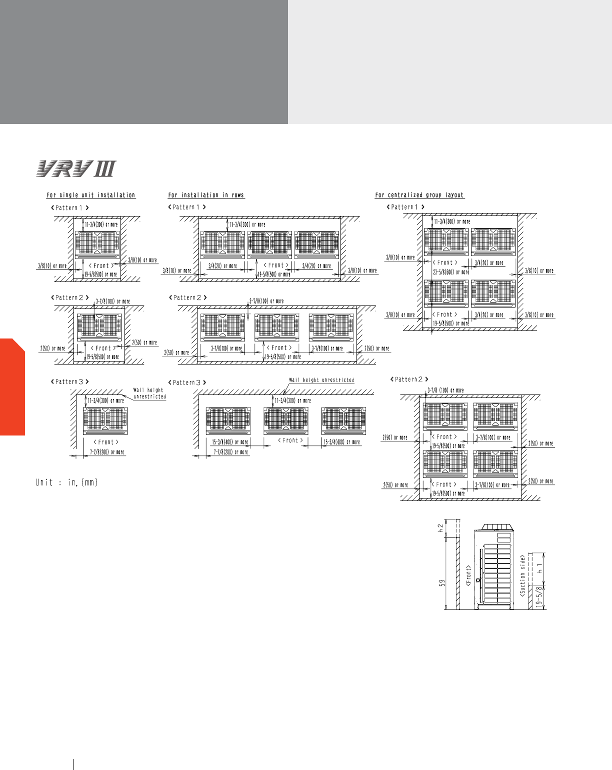
VRV III PC, VRV IV W-Series,
& VRV III-S
Installation Space
Notes
1. Heights of walls in case of Patterns
1 and 2:
Front: 59in.
Suction side: 19-5/8in
Side: Height unrestricted.
Installation space shown in above
are based on the cooling operation
at 95°FDB outdoor air temperature.
The suction side space must be
extended in the following case.
-
When the design outdoor
temperature exceeds 95°FDB.
-
When the heat loads are large and
exceed maximum operating loads
for all outdoor units.
2. When the wall heights exceed
above, add “h2” /2 and “h1” /2
to the front and suction service
spaces respectively. (See right
figure for “h2” and “h1”.)
3. When installing units, the most
appropriate pattern from those
shown above should be selected.
-
a person to pass between the units
and surrounding walls.
-
the air to circulate freely.
-
The possibility of short circuiting
should be evaluated when installing
more units that those shown in the
patterns above.
4. Sufficient space should be provided
in front of the units for refrigerant
piping installation and servicing.
www.daikincomfort.com
98
OUTDOOR UNITS
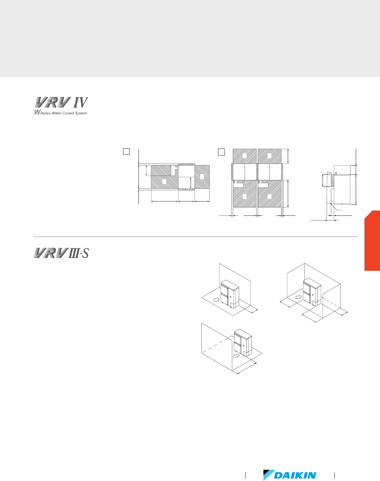
1. In case of a single installation [inch.]
2. In case of multiple unit
installation [inch.]
3. Top view
4. Side view
5. Condensing unit
6. Service Space (front side)
7. Service Space (back side)
8. Space for installing water
piping must be ample enough
to remove the front panel.
9. Ventilation space above the area ( )
of the condensing unit.
10. Secure spaces in the front, back,
and top sides as same as the
case of single installation.
In case of series installation, some space between the units is
needed for wiring with conduit and servicing.
1. Where there is an obstacle on the suction side:
(a) No obstacle above
(1) Stand alone installation
Obstacle on the suction side only
Obstacle on both sides
2. Where there is an obstacle on the discharge side:
(a) No obstacle above
(1) Stand alone installation
35-7/16
13-3/4
13/16
13-3/4
13/16
21-5/8 19-11/16
13/16 13/16 13/16
3-15/16
30-11/16
15-3/8
9
9
8
10
8
9
77
66
6
9
7
8
5
8
[4]
[3]
1
2
11-13/16
39-3/8
35-7/16 19-11/16
9-13/16
4 or more
4 or more
4 or more
20
or more
4 or more
Unit values are in inches
VRV Product Catalog
99
OUTDOOR UNITS
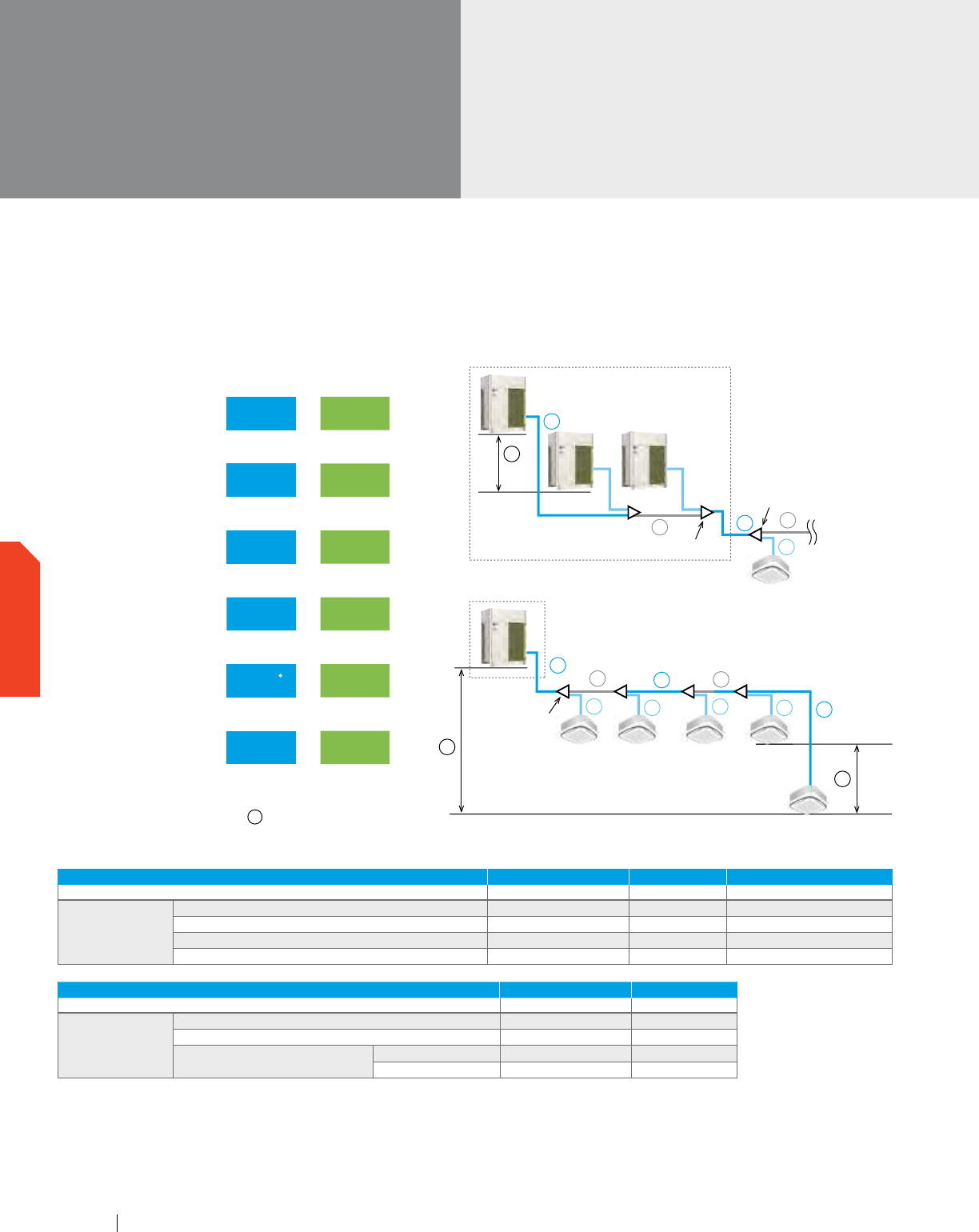
VRV IV, VRV III PC, VRV IV W-Series,
& VRV III-S
Piping length
Max.
100 ft.
Max. 295 ft.
†
For connection of only VRV indoor units
p
q
k
First outdoor unit branch
f
a
b
First indoor
unit branch
Multiple use
The rest of indoor
units are the same
as for single use.
a
i
s
r
h
g
f
e
d
c
b
First indoor
branch
Single use
Colors in the diagram above are merely for identifying
pipes referenced with symbols such as a .
Max. equivalent
piping length
623 ft. 580 ft.
Max. actual piping length
541 ft. 492 ft.
Max. total piping length
3281 ft. 1000 ft.
Max. level difference
between the outdoor units
and the indoor units
295 ft.
†
164 ft.
†
Max. level difference
between the indoor units
100 ft. 49 ft.
295 ft.
131 ft.
Max. distance from 1st
refrigerant branch joint
VRV III PC & VRV IV VRV III-S
The long piping length provides more design flexibility, which can match even large-sized buildings.
Air-cooled system piping length
Piping for VRV IV, VRV III PC and VRV III-S
ACTUAL PIPING LENGTH EXAMPLE EQUIVALENT PIPING LENGTH
VRV-IV / VRV-III-S VRV-IV / VRV-III-S
Maximum allowable
piping length
Refrigerant piping length 541 ft. / 492 ft. a+f+g+h+i 623 ft / 580 ft.
Total piping length 3281 ft. / 1000 ft. a+b+c+d+e+f+g+h+i —
Between the first indoor unit branch and the farthest indoor unit 295 ft.
*
/ 131 ft.
*
f+g+h+i —
Between the outdoor unit branch and the last outdoor unit 33 ft. / n/a k+p 43 ft / n/a
LEVEL DIFFERENCE EXAMPLE
VRV-IV / VRV-III-S
Maximum allowable
level difference
Between the outdoor units (multiple use on the same circuit) 16 ft. / n/a q
Between the indoor units 98 ft. / 49 s
Between the outdoor units and
the indoor units
If the outdoor unit is above 295 ft.
†
/ 164 r
If the outdoor unit is below 295 ft.
/ 164 r
*
No special requirements up to 131 ft. The maximum actual piping length can be 295 ft., depending on conditions. Various conditions and requirements
have to be met to allow utilization of 295 ft. piping length. Be sure to refer to the Engineering Data Book for details of these conditions and requirements.
†
When level differences are 164 ft. or more, the diameter of the main liquid piping size must be increased and connection ratio must be 80% to 130%.
If the outdoor unit is above the indoor unit, a dedicated setting on the outdoor unit is required. Refer to the Engineering Data Book and contact your local
dealer for more information.
100 ft. is supported for VRV-IV. For VRV-III PC, the limit is 49 ft.
www.daikincomfort.com100
OUTDOOR UNITS
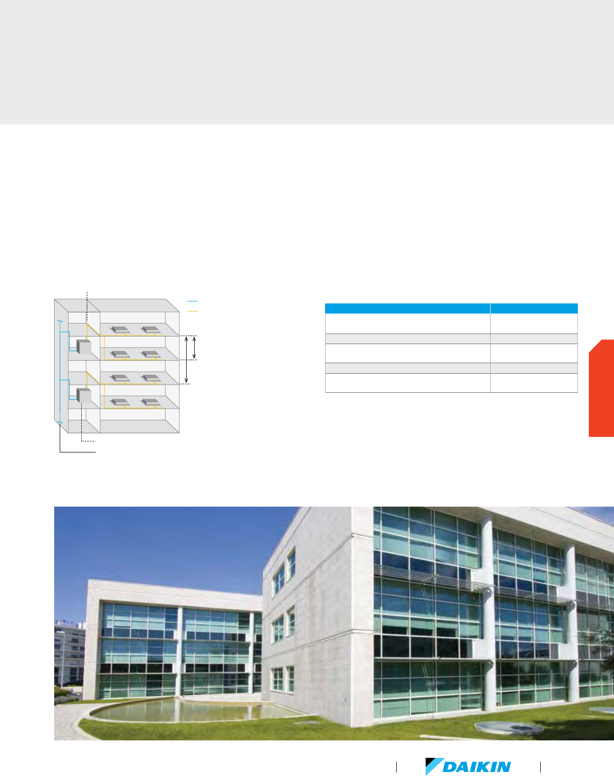
Water-cooled system piping length
Considerable flexibility is available within the refrigerant circuit
since up to 980 ft. actual piping length and 164 ft. (if the
VRV IV W-Series condensing unit is above the indoor unit) in
height can exist between the VRV IV W-Series condensing units
and indoor units. Water piping does not intrude in the occupied
spaces, so there are no potential leakage problems.
REFRIGERANT PIPING LIMITATIONS LIMITATIONS
Linear piping between condensing unit and furthest
located fan coil unit (equivalent), ft.
390 (459)
Total “one-way” piping in the complete piping network, ft. 980
Vertical (height) separation between the condensing unit
and the fan coil units (if condensing unit is below)*, ft.
164 (130)
Vertical (height) separation between fan coil units, ft. 49
Linear piping between 1st REFNET and furthest located
fan coil unit, ft.
130
* For geothermal applications, if the condenser is lower than the indoor units, the maximum vertical
separation is 65 ft.
For connection of only VRV indoor units
Actual piping length between the VRV IV W-Series and
indoor units: 390 ft. (equivalent piping length: 459 ft.)
Water piping
Refrigerant piping
Level difference between
indoor units: 49 ft.
Level difference between the
VRV IV W-Series and indoor units:
164 ft. if the VRV IV W-Series is above
130 ft. if the VRV IV W-Series is below
Indoor installation of condensing unit
Water piping length depends on the heat source equipment
VRV Product Catalog
101
OUTDOOR UNITS
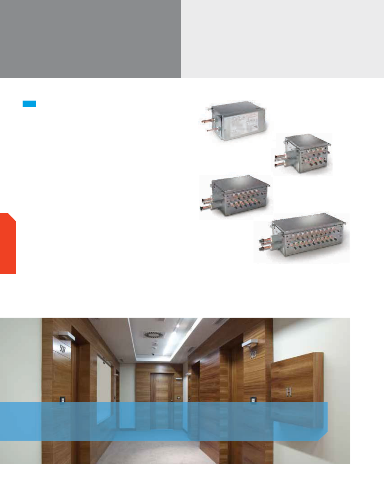
VRV Accessories
Branch Selector
Boxes
BSQ36TVJ, BSQ60TVJ,
& BSQ96TVJ Single Port
BS4Q54TVJ
BS10Q54TVJ
BS6Q54TVJ
NEW
Branch Selector Boxes for Heat Recovery Systems
Providing flexibility and minimizing mechanical and electrical
installation costs, Daikin's branch selector boxes are ideal for
spaces that require individual heating and cooling control.
Extended range of product offerings with
1, 4, 6, 8, 10 and 12 port options
No drain or condensate
consideration required
Unlimited number of unused ports per
box or system
Reduced electrical and mechanical
installation costs
Ultimate flexibility – Choose multi-port or
single-port styles to customize your design
Up to 72% reduction in footprint, as compared
to previous generation models
Up to 17% lower sound levels compared to
current VRV III models
Up to 65% reduction in weight, as compared
to previous generation models
Branch Selector Boxes Compatibility
Single-Port and Multi-Port Branch Selector Boxes BS-TVJ Series
are compatible with VRV IV, VRV IV W-Series and VRV III
REYQ-PC Series.
Daikin's branch selector boxes are ideal for spaces that require individual
heating and cooling control.
www.daikincomfort.com102
OUTDOOR UNITS
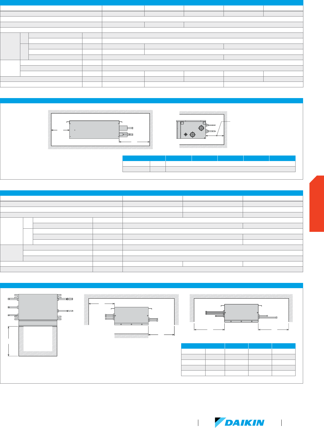
TECHNICAL DATA FOR SINGLE-PORT BRANCH SELECTOR BOXES
Model BSQ36TVJ BSQ60TVJ BSQ96TVJ
Number of branches 1 1 1
Maximum capacity index 36 60 96
Maximum connectable indoor units 4 8 8
Connecting
Pipes
IU
Liquid in. Ø3/8
Gas in. Ø5/8 Ø7/8
IU
Liquid in. Ø3/8
Suction Gas in. Ø5/8 Ø7/8
HP/LP Gas in. Ø1/2 Ø3/4
Electrical
Power Supply ph/V/Hz 1/208-230/60
Maximum Overcurrent Protection, MOP A 15
Minimum Circuit Amps, MCA A 0.1
Mass (Weight) lbs 27 27 33
Dimensions (H x W x D) in. 8-1/8 x 15-1/4 x 12-13/16
TECHNICAL DATA FOR MULTI-PORT BRANCH SELECTOR BOXES
Model BS4Q54TVJ BS6Q54TVJ BS8Q54TVJ BS10Q54TVJ BS12Q54TVJ
Number of branches 4 6 8 10 12
Maximum capacity index per branch 54
Maximum total capacity index 144 216 290
Maximum connectable indoor units per branch 5
Connecting
Pipes
IU
Liquid in. Ø1/4, Ø3/8
Gas in. Ø1/2, Ø5/8
IU
Liquid in. Ø3/8 Ø1/2 Ø5/8
Suction Gas in. Ø7/8 Ø1-1/8
HP/LP Gas in. Ø3/4 Ø1-1/8
Electrical
Power Supply ph/ V/Hz 1/208-230/60
Maximum Overcurrent Protection, MOP A 15
Minimum Circuit Amps, MCA A 0.6 0.8 1 1.2
Mass (Weight) lbs 49 68 73 101 106
Dimensions (H x W x D) in. 11-3/4 x 14-9/16 x 18-15/16 11-3/4 x 22-13/16 x 18-15/16 11-3/4 x 32-5/16 x 18-15/16
For additional technical information and all equipment installation and application limitations please refer to the specific Engineering Data Books.
MULTI-PORT BRANCH SELECTOR BOX INSTALLATION SPACE
MINIMUM CLEARANCE BS4Q54TVJ BS6Q54TVJ BS8Q54TVJ BS10Q54TVJ BS12Q54TVJ
A in . 20
B in . 11-3/4
SINGLE-PORT BRANCH SELECTOR BOX INSTALLATION SPACE
(E
)
(B)
(A)
(C) (D)
MINIMUM CLEARANCE BSQ36TVJ BSQ60TVJ BSQ96TVJ
A in . 10 10 12
B in . 10 10 12
C in . - 13-3/4 15-3/4
D in . 12 13-3/4 15-3/4
E in . 12 12 11-13/16
(B)
(A)
Field Specific
Minimum
Clearance
VRV Product Catalog
103
OUTDOOR UNITS
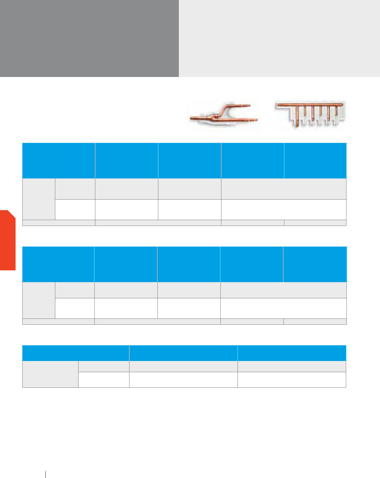
VRV Accessories
REFNET
pipe joints
REFNET
REFNET joints distribute correct flow of refrigerant
in every branch of the piping network.
VRV IV Heat Pump
OPTIONAL ACCESSORIES
RXYQ72T
RXYQ96T
RXYQ120T
RXYQ144T
RXYQ168T
RXYQ192T
RXYQ216T
RXYQ240T
RXYQ264T
RXYQ288T
RXYQ312T
RXYQ336T
RXYQ360T
RXYQ384T
RXYQ408T
Distributed piping
Refnet header
KHRP26M22H (max. 4 branch)
KHRP26M33H (max. 8 branch)
KHRP26M22H (max. 4 branch)
KHRP26M33H (max. 8 branch)
KHRP26M72H (max. 8 branch)
K
HRP26M22H (max. 4 branch)
KHRP26M33H (max. 8 branch)
KHRP26M72H (max. 8 branch)
KHRP26M73H (max. 8 branch)
R
efnet joint
KHRP26A22T
KHRP26A33T
KHRP26A22T
KHRP26A33T
KHRP26M72TU
K
HRP26A22T
KHRP26A33T
KHRP26M72TU
KHRP26M73TU
O
utdoor unit multi connection piping kit — BHFP22P100U BHFP22P151U
VRV IV Heat Recovery
OPTIONAL ACCESSORIES
REYQ72T
REYQ96T
REYQ120T
REYQ144T
REYQ168T
REYQ192T
REYQ216T
REYQ240T
REYQ264T
REYQ288T
REYQ312T
REYQ336T
REYQ360T
REYQ384T
REYQ408T
REYQ432T
REYQ456T
Distributed piping
Refnet header KHRP26M33H (max. 8 branch)
KHRP26M33H (max. 8 branch)
KHRP26M72H (max. 8 branch)
KHRP25M33H9 (max. 8 branch)
KHRP25M72H9 (max. 8 branch)
KHRP25M73H9 (max. 8 branch)
R
efnet joint
KHRP25A22T9
KHRP25A33T9
KHRP25A22T9
KHRP25A33T9
KHRP25M72TU9
K
HRP25A22T9
KHRP25A33T9
KHRP25M72TU9
KHRP25M73TU9
O
utdoor unit multi connection piping kit — BHFP26P100U BHFP26P151U
REFNET Joint REFNET Header
VRV III PC Heat Recovery
OPTIONAL ACCESSORIES REYQ72PC
REYQ96PC
REYQ120PC
REYQ144PCTJ
Distributed piping
Refnet header KHRP25M33H9 (max. 8 branch)
KHRP25M33H9 (max. 8 branch)
KHRP25M72H9 (max. 8 branch)
Refnet joint
KHRP25A22T9
KHRP25A33T9
K
HRP25A22T9
KHRP25A33T9
KHRP25M72TU9
www.daikincomfort.com104
OUTDOOR UNITS
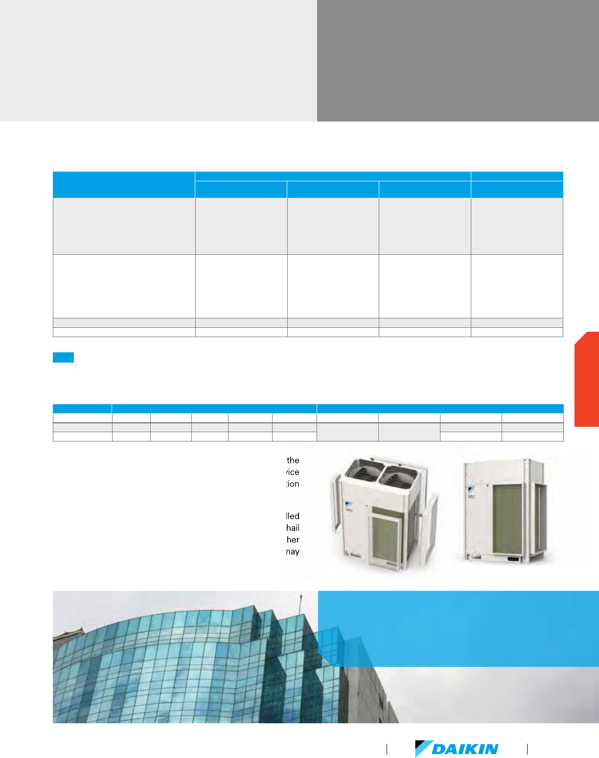
Daikin VRV IV provides a solution
for large commercial applications
desiring heating or cooling.
NEW
Hail Guard Kit for VRV IV
The optional hail guard kit for VRV IV enables optimal airflow for efficient heat transfer while providing condenser coil protection
from hail damage in severe climates. Each hail guard kit, that is field installed, consists of 4 panels (Right, Left, Front and Back).
VRV Accessories
REFNET pipe joints &
Hail Guard Kit for VRV IV
Service space requirements for the front, back and sides of the
condensing unit must be at least 4" greater than the service
space requirements provided in the condensing unit installation
manual and engineering guide.
If the condensing units in multiple unit installations are installed
between 0.75" and 3" maximum between units, the side hail
guard panels between modules may not be required. For further
separation between the modules, full kits for each module may
be required.
KIT PART NUMBER QTY OF KITS PER VRV IV OU MODEL PANEL DIMENSIONS (H X W X D)
R_YQ72T R_YQ96-168T R_YQ192T
R_YQ216-336T
R_YQ360-408T Right Panel Left Panel Front Panel Front Panel
VRV4HGS-K1 1 1 1
45.90" x 26.07" x 4.00" 45.90" x 12.88" x 4.00"
45.90" x 13.24" x 4.00" 45.90" x 32.62" x 4.00"
VRV4HGL-K1 1 2 3 45.90" x 24.03" x 4.00" 45.90" x 44.77" x 4.00"
Service space requirements for the front, back and sides of the
greater than the service
space requirements provided in the condensing unit installation
If the condensing units in multiple unit installations are installed
maximum between units, the side hail
guard panels between modules may not be required. For further
separation between the modules, full kits for each module may
VRV IV W-Series Heat Pump / Heat Recovery and VRV-III-S
UNIT MODEL NUMBER
VRV IV W-SERIES VRV-III-S
RWEYQ72P
RWEYQ84P
RWEYQ144P
RWEYQ168P
RWEYQ168P
RWEYQ252P
RXYMQ36P
RXYMQ48P
REFNET Header
KHRP25M33H9 (max. 8 branch)
KHRP26M22H9 (max. 4 branch)
KHRP26M33H9 (max. 8 branch)
KHRP25M33H9 (max. 8 branch)
KHRP25M72H9 (max. 8 branch)
KHRP26M22H9 (max. 4 branch)
KHRP26M33H9 (max. 8 branch)
KHRP26M72H9 (max. 8 branch)
KHRP25M33H9 (max. 8 branch)
KHRP25M72H9 (max. 8 branch)
KHRP25M73HU9 (max. 8 branch)
KHRP26M22H9 (max. 4 branch)
KHRP26M33H9 (max. 8 branch)
KHRP26M72H9 (max. 8 branch)
KHRP26M73HU9 (max. 8 branch)
KHRP26M22H9 (max. 4 branches)
KHRP26M33H9 (max. 8 branches)
REFNET Joint
KHRP25M22T9
KHRP25M33T9
KHRP26M22T9
KHRP26M33T9
KHRP25M22T9
KHRP25M33T9
KHRP25M72TU9
KHRP26M22T9
KHRP26M33T9
KHRP26M72TU9
K
HRP25M22T9
KHRP25M33T9
KHRP25M72TU9
KHRP25M73TU9
KHRP26M22T9
KHRP26M33T9
KHRP26M72TU9
KHRP26M73TU9
K
HRP26M22T9
Outdoor Unit Multi Piping Connection Kit (Heat Pump) BHFP22MA56U BHFP22MA84U
Outdoor Unit Multi Piping Connection Kit (Heat Recovery) BHFP26MA56U BHFP26MA84U
VRV Product Catalog
105
OUTDOOR UNITS
www.daikincomfort.com106
VRV Product Catalog
107
Ventilation

Daikin’s Outside Air Processing Unit can be integrated with a
VRV system to provide outside air treatment and air conditioning
in a single system to meet code requirements. It adjusts the
temperature of air from outdoors using a fixed discharge
temperature control reducing air conditioning load.
In addition to Outside Air Processing Units, we also offer Energy
Heat Recovery units. The Energy Heat Recovery VAM-GVJU
series units combines compactness, energy conservation, and
extensive operation range of outdoor temperatures. This series
provides higher enthalpy efficiency, due to the greatly enhanced
performance of the thin heat exchanging element. Furthermore,
improved external static pressure offers more flexibility
for installation.
Daikin’s air treatment systems — creating a better air quality environment.
Air Treatment Systems
VENTILATION
www.daikincomfort.com108
OUTSIDE AIR PROCESSING UNIT, FXMQ-MFVJU ENERGY RECOVERY VENTILATOR, VAM-GVJU
VRV Refrigerant Piping Connectable Not connectable
VRV Control Wiring Connectable
High Efficiency Filter (MERV 8 and MERV 13) Option Not available
Ventilation System Air supply Air supply and Air exhaust
Power Supply V/ph/Hz 208-230/1/60
Airflow Rate CFM 635
988
1236
300/300/170
470/470/390
600/600/500
1200/1200/930
VENTILATION
VRV Product Catalog
109
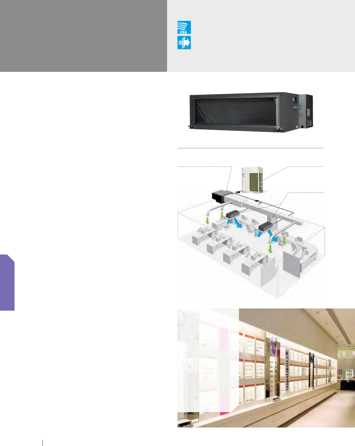
www.daikincomfort.com110
Concealed, Powerful, Compact,
Quiet, Fresh Air Quality
This unit provides a zoned, decentralized approach to conditioning
outside air. This helps to reduce ductwork and installation time
while increasing efficiency and flexibility. Both outside air
treatment and space conditioning can be provided from one
compact, flexible and efficient VRV system. VRV indoor units
and outdoor air processing unit can be connected to the same
refrigerant line, enabling enhanced design flexibility.
Features and Benefits
Available in three capacities, nominal 48, 72 and 96 MBH
The nominal airflow rates are 635, 988,
and 1,236 CFM respectively
External static pressure capabilities of up to 1.03" W.G.
allows for flexibility with duct work and filtration choices
The indoor unit is controlled to a set cooling
and heating discharge air temperature allowing
the flexibility to integrate with a standard Daikin
indoor unit or duct directly to the space
A low profile design of only 18.5" high reduces
the required installation space and can eliminate
mechanical rooms or additional structural supports
associated with traditional OA systems
Indoor Air Quality options include MERV
8 and 13 filters and filter boxes
Can be connected to all North American
Daikin VRV systems
Connects directly and seamlessly into the
Daikin local and centralized controllers
Operational Characteristics
When the suction air temperature is between 66°F and 109°F,
the Outside Air Processing Unit operates in cooling, and when
between 23°F and 59°F, it operates in heating. The OA processing
unit will work in energy saving fan only between 59°F and 66°F.
FXMQ-MFVJU
100% Outside Air
Processing Unit
Layout example
Outside air processing unit
for outside air supply
VRV indoor unit
for air-conditioning
Applications
Hotel/
conference
centers
Schools
Retail
shopping
centers
Large open-
plan offices
Churches
VRV outdoor unit
Outside Air
Integration Possible
Filter
Included
VENTILATION
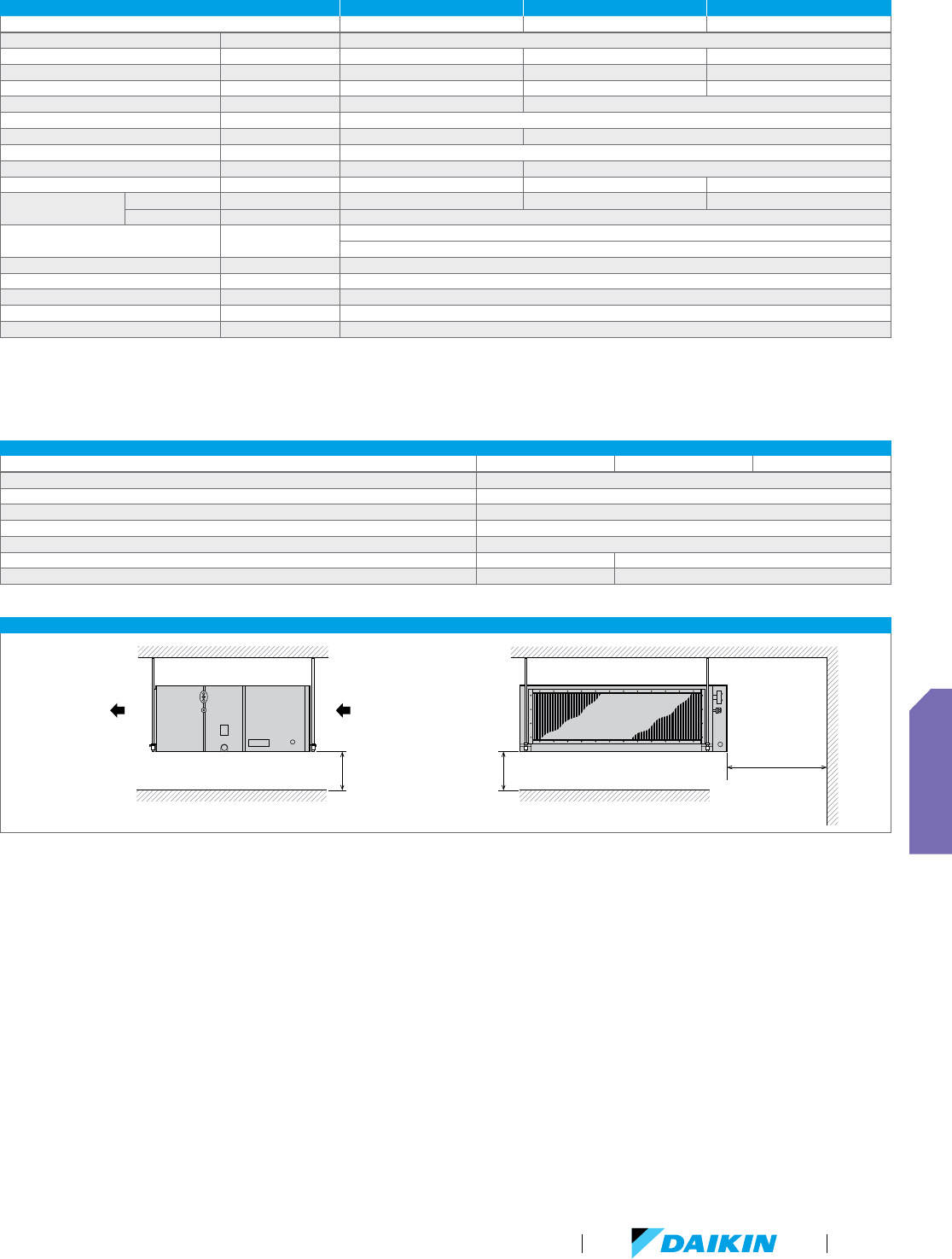
VRV Product Catalog
111
FXMQ-MFVJU ACCESSORIES
Model Name FXMQ48MFVJU FXMQ72MFVJU FXMQ96MFVJU
Navigation Remote Controller BRC1E73
Wireless Remote Controller BRC4C82
Remote Sensor Kit KRCS01-1B
Wiring Adapter PCB (interface with aux/primary heater, humidifier, OA damper/fan) KRP1C74
Group Control Adapter PCB (connects to external BMS) KRP4A71
High Efficiency Filter Kit (MERV 13) DACA-MQ48F131K DACA-MQ96F131K
High Efficiency Filter Kit (MERV 8) DACA-MQ48F-8-1K DACA-MQ96F-8-1K
FXMQ-MFVJU INSTALLATION SPACE
Discharge Side
Ceiling
Suction Side
2.5"
or more
2.5"
or more
25-9/16"
or more
Ceiling
FXMQ-MFVJU SPECIFICATIONS 4 TON 6 TON 8 TON
Model Name FXMQ48MFVJU FXMQ72MFVJU FXMQ96MFVJU
Power Supply V/ph/Hz 208-230/1/60
Rated Cooling Capacity BTU/h 48,000 72,000 96,000
Rated Heating Capacity BTU/h 30,000 47,000 59,000
Airflow Rate CFM 635 988 1,236
Weight lbs 190 271
Height in. 18-1/2
Width in. 29-1/4 54-3/8
Depth in. 43-5/16
Sound Pressure dB(A) 42 47
External Static Pressure in. W.G. 0.88 0.96 1.03
Pipe Connections
Gas in. 5/8 3/4 7/8
Liquid in. 3/8
Protection Devices
Fuse
Fan Motor Thermal Protector
External Finish Galvanized Steel Plate
Operating Range - Cooling °F 66 DB/59 WB - 109 DB/90 WB
Operating Range - Heating °F 23 DB to 59 DB
Discharge Air Temp. - Cooling °F 55-77
Discharge Air Temp. - Heating °F 64-86
Nominal Conditions: Cooling Mode
Discharge Set Temperature: 64 °F DB
Outdoor: 91 °F DB, 82 °F WB (68% RH)
Pipe Length: 25 ft.
Level Difference: 0 ft.
H
eating Mode
Discharge Set Temperature: 77 °F DB
Outdoor: 32 °F DB, 27 °F WB (50% RH)
Pipe Length: 25 ft.
Level Difference: 0 ft.
No
te: Specifications are subject to change
without notice.
VENTILATION
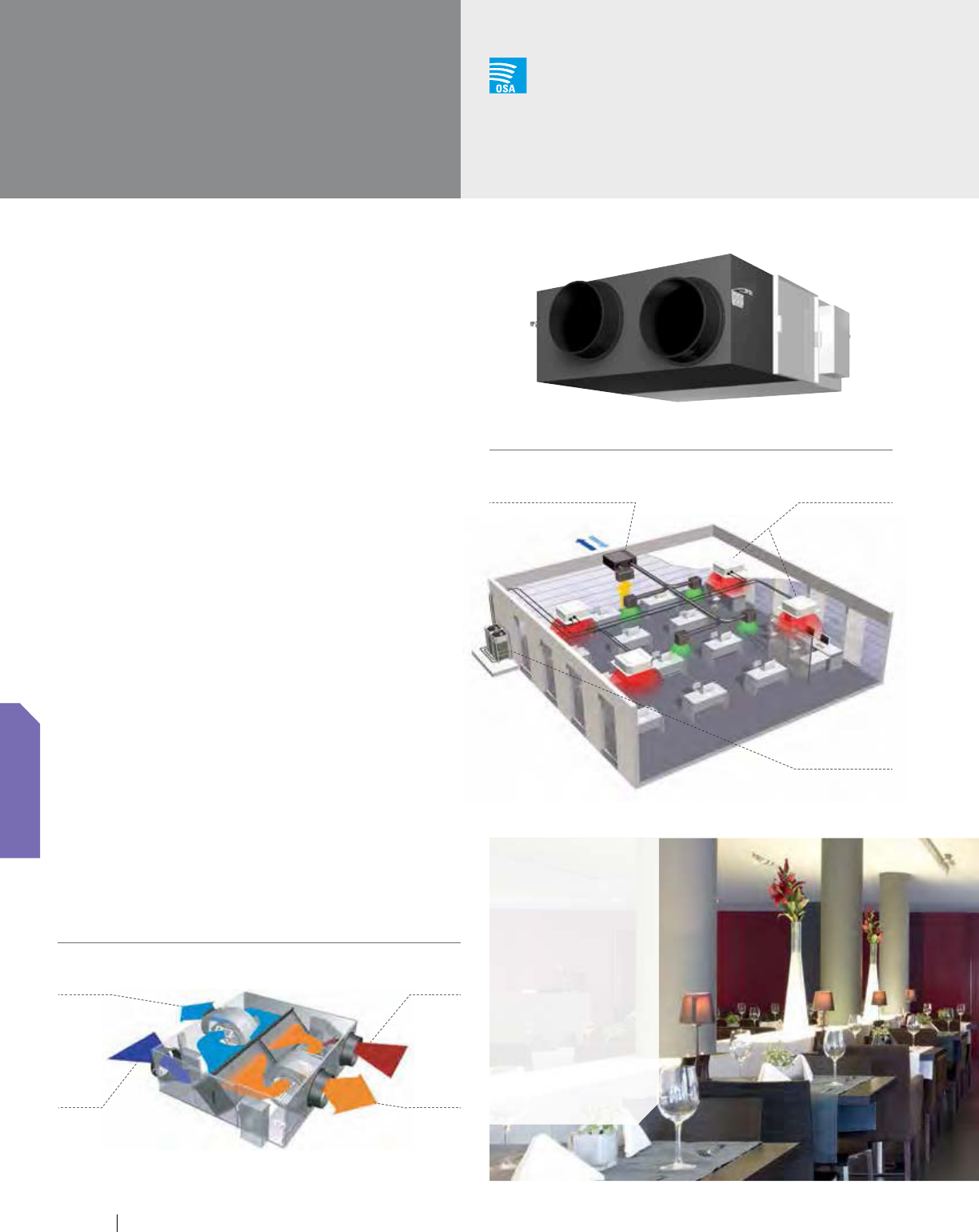
www.daikincomfort.com11 2
Energy Efficient, Logical, Compact
This Energy Recovery Ventilator is designed to maintain good
indoor air quality by providing sufficient levels of outside air and
recover waste heat from exhaust air leaving the conditioned zone.
It is also fully compatible with Daikin’s DIII-NET communications.
Features and Benefits
Provides energy saving heat recovery ventilation
via a heat exchanger with temperature
and enthalpy recovery efficiency
0-4% return cross leakage rating
Superior performance with a high efficiency fan and
the capability for use in a wide range of climates
(5 to 122°FDB and 80% RH or less)
Unique functions such as independent operation, third
party equipment interlocking and automatic night purge
to reduce cooling loads and increase energy savings
Interlocked simultaneous operation with VRV indoor units
Pre-cooling/heating control function to delay
the start of ventilation during air conditioner
start-up for higher energy savings
Supply and exhaust fresh-up operation modes
to help control pressure within a space
Filter sign and display reset notifies
when filter changes are required
Temperature recovery efficiency up to 74%
Enthalpy recovery efficiency up to 65%
ESP as high as 0.76" W.G.
Sound levels as low as 25.5 dB(A) for
sound sensitive installation locations
VAM-GVJU
Energy Recovery
Ventilator
Outside Air
Integration Possible
EA
(Exhaust to
outdoors)
OA
(Air from
outdoors)
RA
(Return air
from room)
SA
(Supply air
to room)
Heat exchanger with high temperature and enthalpy efficiency
Layout example
Energy Recovery Ventilator
for outside air supply
VRV indoor unit
for air-conditioning
Applications
Hotel/
conference
centers
Schools
Retail
shopping
centers
Large open-
plan offices
Churches
VRV outdoor unit
VENTILATION
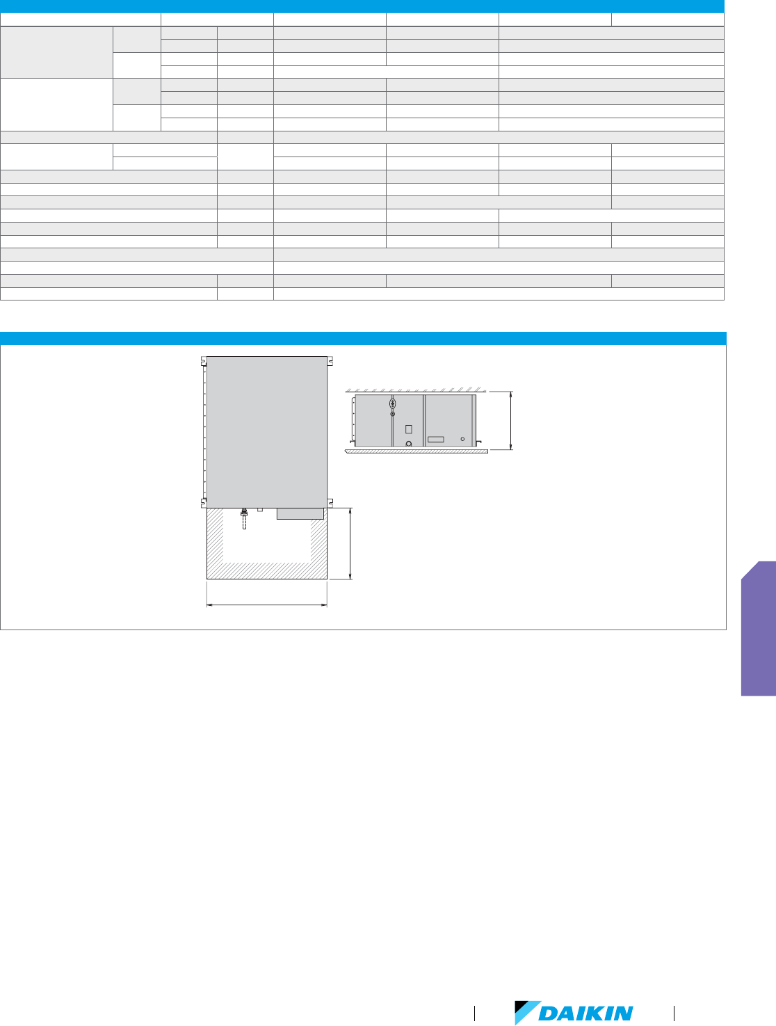
VRV Product Catalog
11 3
VAM-GVJU INSTALLATION EXAMPLE
Energy Recovery
Ventilator
(Top View)
26" or more
21" or more
(Service space)
44" or more
(Service space)
VAM SPECIFICATIONS
Model Name Airflow VAM300GVJU VAM470GVJU VAM600GVJU VAM1200GVJU
Temperature Recovery
Efficiency Percentage
Cooling
100 % 65 68 72
75 % 70 72 74
Heating
100 % 65 66 70
75 % 69 73
Enthalpy Recovery
Efficiency Percentage
Cooling
100 % 40 45 49
75 % 48 50 52
Heating
100 % 57 59 60
75 % 63 65 63
Power Supply V/ph/Hz 208-230/1/60
Airflow Rate (H/M/L)
Heat Exchange Mode
CFM
300/300/170 470/470/390 600/600/500 1,200/1,200/930
Bypass Mode 300/300/170 470/470/390 600/600/500 1,200/1,200/930
Weight lbs 71 121 148 346
Height in. 12-1/16 15-1/4 15-1/4 30-7/8
Width in. 34-5/8 43-11/16 63-3/4
Depth in. 31-1/2 32-3/4 47-13/16
Sound Pressure (H/M/L) dB(A) 37/33.5/25.5 42/38.5/35 42.5/39/36 44.5/41.5/38.5
External Static Pressure (H/M/L) in. W.G. 0.64/0.26/0.16 0.73/0.39/0.33 0.76/0.34/0.32 0.56/0.24/0.16
External Finish Galvanized Steel Plate
Insulation Material Self-Extinguishing Urethane Foam
Connection Duct Diameter in. 8 10 14
Ambient Conditions A 5°F ~ 122°FDB 80% RH or less
VENTILATION

www.daikincomfort.com114

VRV Product Catalog
11 5
Controls
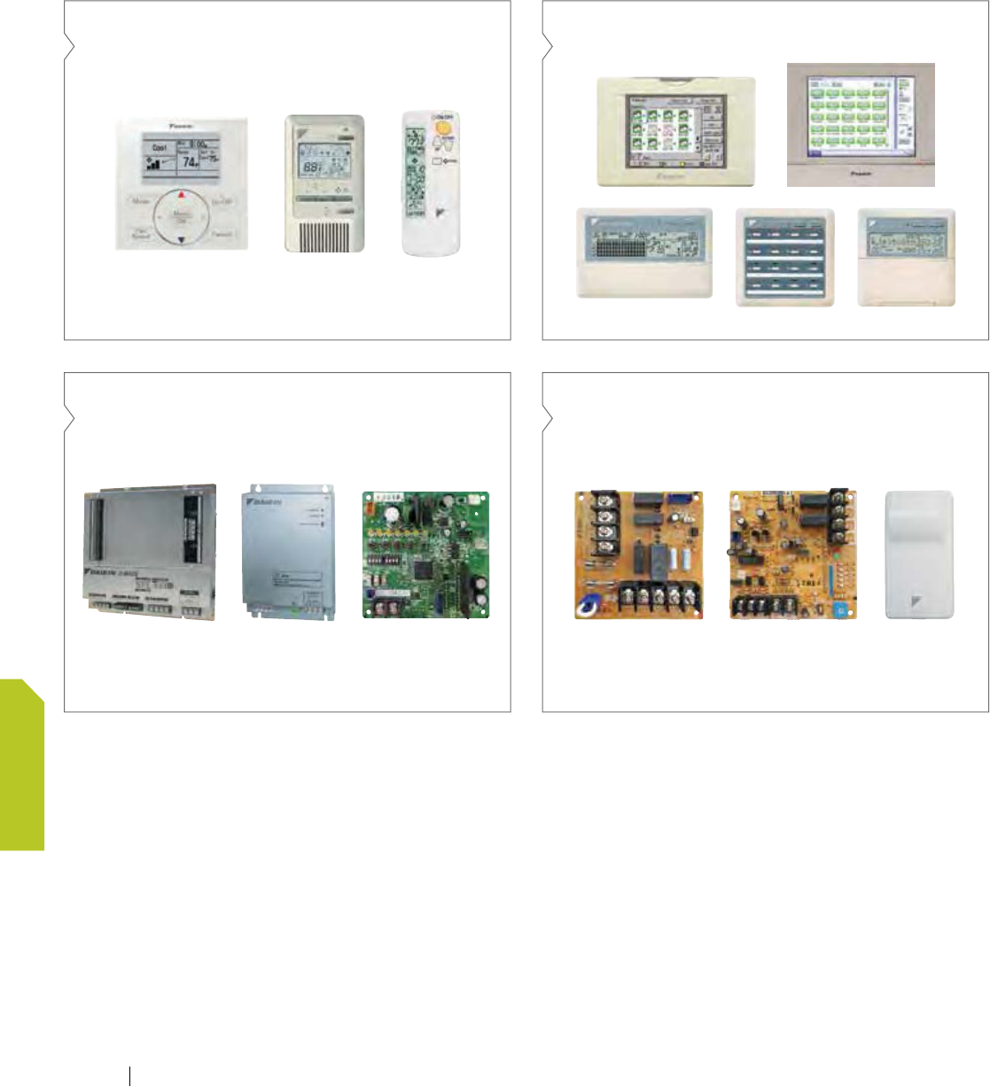
VRV controls matrix
What are your choices?
Individual zone controllers Multi-zone controllers
Open protocol interfaces Adapter PCB’s
www.daikincomfort.com11 6
CONTROLS
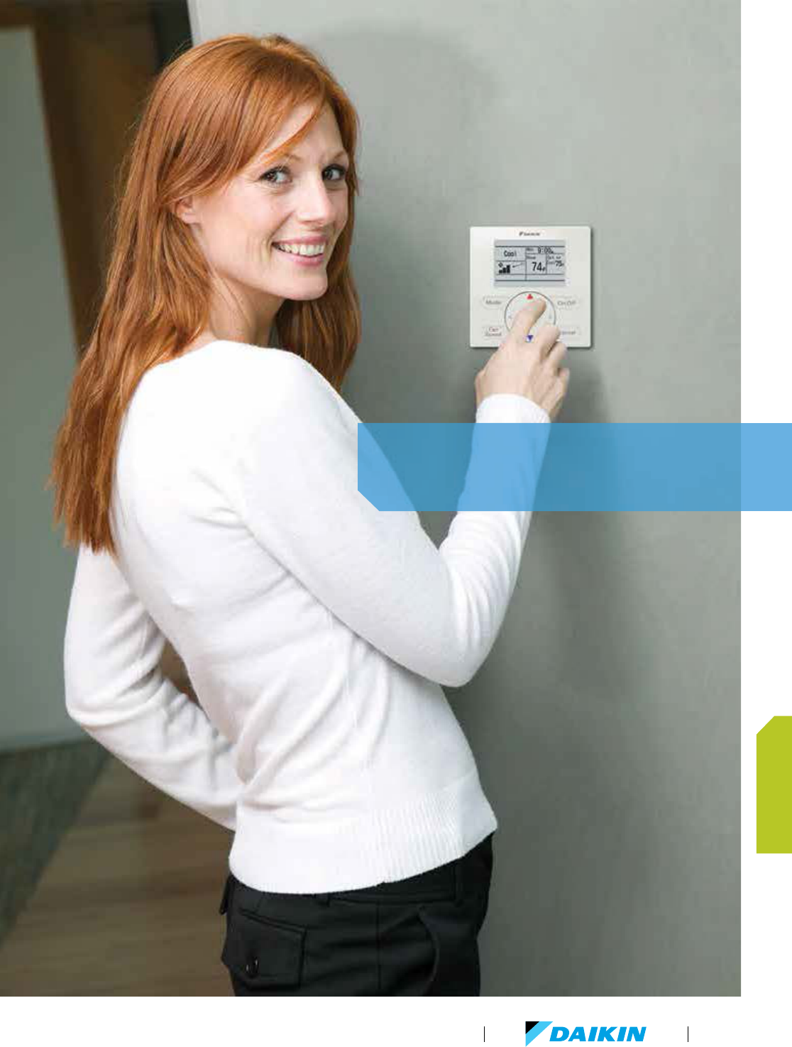
Daikin controls offer comfort control in
an easily managed and operated system.
VRV Product Catalog
11 7
CONTROLS

VRV control systems
(DCM601A71)
WAGO I/O
Interface adapter
for SkyAir series
(DTA112BA51)
Interface adapter
for DIII-NET use
(KRP928BB2S)
Central Remote
Controller
(DCS302CA61)
(DCS601C71)
Schedule Timer
(DST301BA61)
Unified ON/OFF
Controller
(DCS301BA61)
Unification adapter
for computerized control
(DCS302A52)
Modus interface adapter
(DTA116A51)
Home automation
master controller
DIII-NET Line
BACnet
®
/Ethernet or LONWORKS
®
network communication line
RS485 Modbus line
Contact signal line
D-NET Air Conditioning
Network Service System
(Optional maintenance service)
Control / connection interface
Building control system
Interface for use in BACnet
®
(DMS502B71)
Interface for use in LONWORKS
®
(DMS504C71)
ACC Center
(Air conditioning Control Center)
Di unit
(DEC101A51-US2)
Dio unit
(DEC102A51-US2)
Building services equipment
Electrical equipment
Ventilation equipment
Lighting
Sensors
Controllers for centralized control
The VRV controls system provides an advanced architecture that ensures optimum comfort and building management.
The DIII-NET system provides for:
Close control and monitoring by integrating a wide
variety of indoor units throughout the entire building.
Saves on in-building wiring cost by using
two-conductor non-polar wiring. Simple wiring helps
to reduce wiring errors.
Modular build-up of the VRV system with a total
wiring length of up to 6560 ft.
Multiple equipment control options that can seamlessly
control equipment.
VRV
Energy recovery ventilator
Multi-split
Split systems
Via internet
Via internet
DIII-NET
(Communications Transmission)
DIII-NET, Daikin’s unique communication
transmission system, links indoor units and
various other building equipment―in
accordance with applications, scale and
conditions―and transmits vast amounts of
information between them.
Limitation may apply to some models and functions. Please contact your local sales office for details.
Note: BACnet
®
is a registered trademark of American Society of Heating, Refrigerating and
Air-Conditioning Engineers (ASHRAE). LONWORKS
®
is a trademark of Echelon Corporation
registered in the United States and other countries.
BMS
iTM BACnet
®
Client (option)
(DOAS)
www.daikincomfort.com11 8
CONTROLS
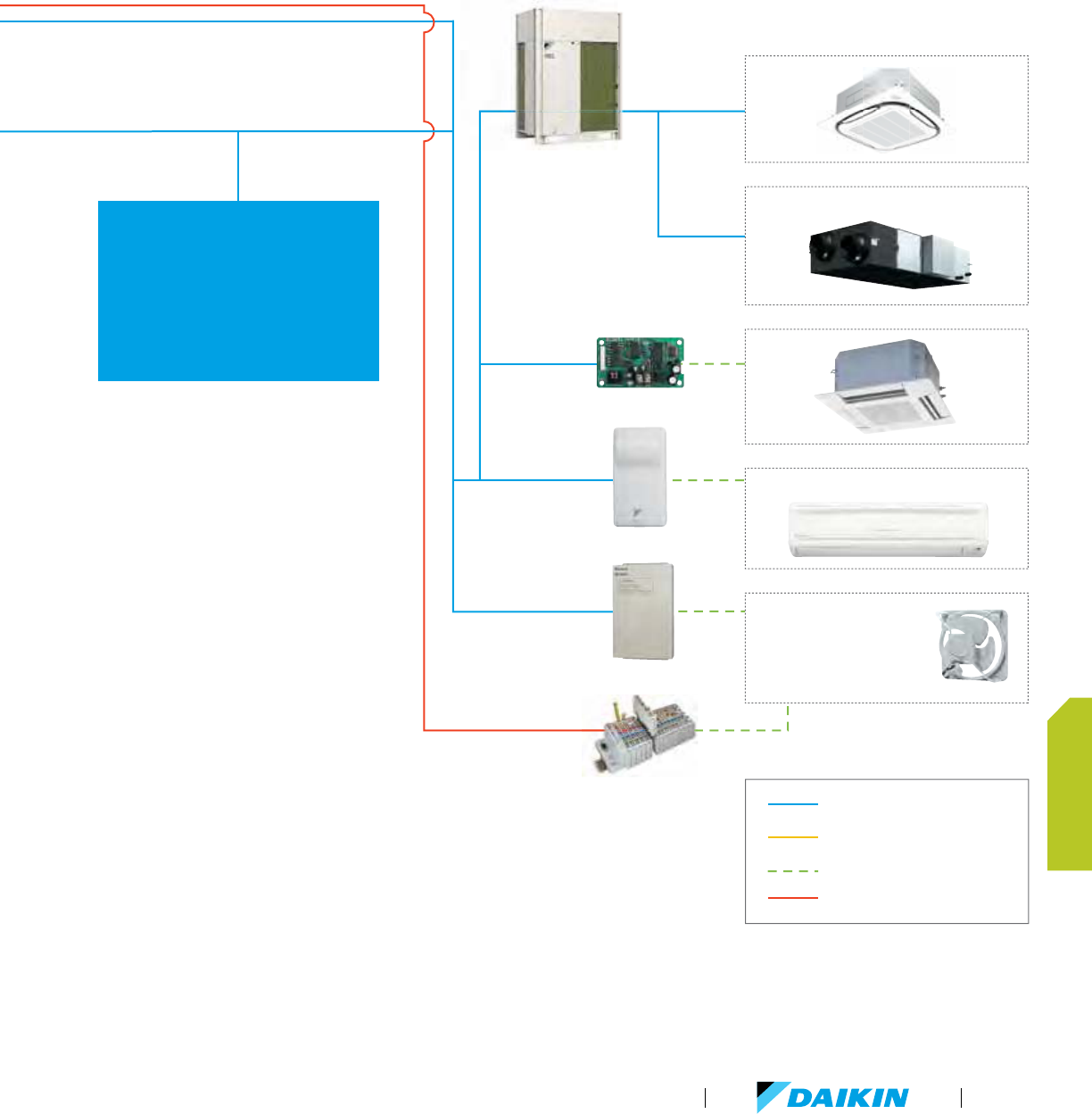
(DCM601A71)
WAGO I/O
Interface adapter
for SkyAir series
(DTA112BA51)
Interface adapter
for DIII-NET use
(KRP928BB2S)
Central Remote
Controller
(DCS302CA61)
(DCS601C71)
Schedule Timer
(DST301BA61)
Unified ON/OFF
Controller
(DCS301BA61)
Unification adapter
for computerized control
(DCS302A52)
Modus interface adapter
(DTA116A51)
Home automation
master controller
DIII-NET Line
BACnet
®
/Ethernet or LONWORKS
®
network communication line
RS485 Modbus line
Contact signal line
D-NET Air Conditioning
Network Service System
(Optional maintenance service)
Control / connection interface
Building control system
Interface for use in BACnet
®
(DMS502B71)
Interface for use in LONWORKS
®
(DMS504C71)
ACC Center
(Air conditioning Control Center)
Di unit
(DEC101A51-US2)
Dio unit
(DEC102A51-US2)
Building services equipment
Electrical equipment
Ventilation equipment
Lighting
Sensors
Controllers for centralized control
The VRV controls system provides an advanced architecture that ensures optimum comfort and building management.
The DIII-NET system provides for:
Close control and monitoring by integrating a wide
variety of indoor units throughout the entire building.
Saves on in-building wiring cost by using
two-conductor non-polar wiring. Simple wiring helps
to reduce wiring errors.
Modular build-up of the VRV system with a total
wiring length of up to 6560 ft.
Multiple equipment control options that can seamlessly
control equipment.
VRV
Energy recovery ventilator
Multi-split
Split systems
Via internet
Via internet
DIII-NET
(Communications Transmission)
DIII-NET, Daikin’s unique communication
transmission system, links indoor units and
various other building equipment―in
accordance with applications, scale and
conditions―and transmits vast amounts of
information between them.
Limitation may apply to some models and functions. Please contact your local sales office for details.
Note: BACnet
®
is a registered trademark of American Society of Heating, Refrigerating and
Air-Conditioning Engineers (ASHRAE). LONWORKS
®
is a trademark of Echelon Corporation
registered in the United States and other countries.
BMS
iTM BACnet
®
Client (option)
(DOAS)
VRV Product Catalog
119
CONTROLS
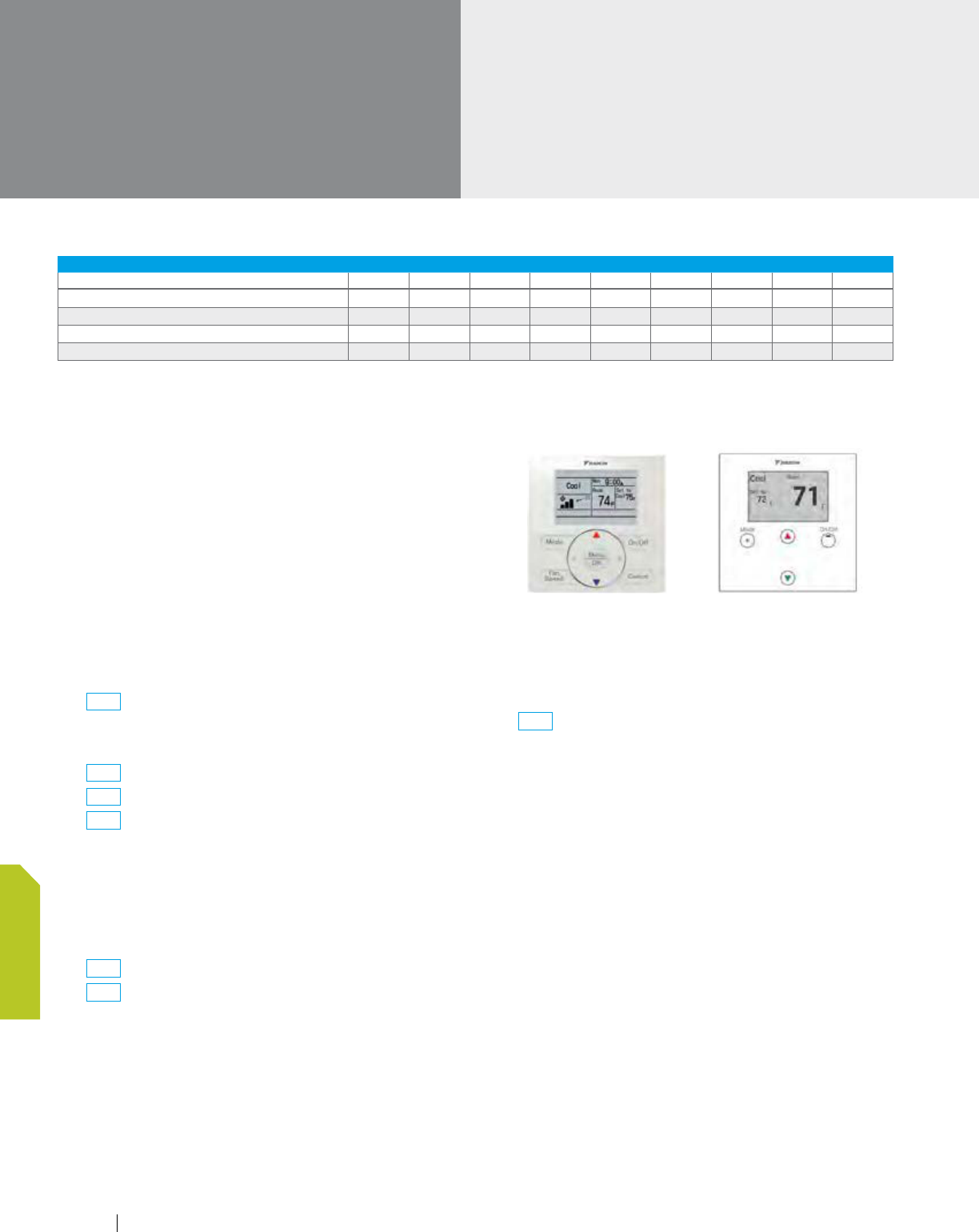
Individual controllers
BRC1E73 - Navigation Remote Controller
New and Improved
The Navigation Remote Controller has been enhanced to meet
the configuration requirements of Daikin’s new VRV indoor units
(FXFQ-TVJU and FXUQ-PVJU). The BRC1E73 will provide all the
great features and options the market requires. The configurable
display and operation buttons will provide as much or as little
control as the project requires.
Features and Benefits
Basic Operation
-
On/Off, operation mode, setpoint
-
NEW
Up to 5 fan speeds selectable
-
Fan speed (enhanced)
-
Airflow direction (enhanced)
-
NEW
Individual louver airflow direction
-
NEW
Dual airflow
-
NEW
Auto-draft prevention (prevents air
blowing directly on occupants)
Function
-
Configurable display — Detailed, Standard, and Simple
-
Dual or single cool and heat setpoints for occupied periods
-
Independent setback setpoints for unoccupied periods
-
NEW
Automatic Setback by occupancy sensor
-
NEW
Automatic Off by occupancy sensor
-
Unwanted buttons/operation modes can be disabled
-
Setpoint range limitation
-
Individual button prohibits/lockout
-
Auto-changeover for Heat Recovery and Heat Pump
systems with dual or single setpoints
-
NEW
Self-cleaning filter panel
-
Automatic adjustment for Daylight
Savings Time (DST) (enhanced)
-
Built in 7, 5+2, 5+1+1, and 1 (everyday) schedule with up
to 5 actions per day with independent cooling, heating and
setback setpoints
More Features
-
Backlit display
-
Room temperature sensor
-
12/24 hour clock
-
Fahrenheit/celsius selectable
-
English/French/Spanish languages selectable
-
Remote control group - up to 16 indoor units
REMOTE CONTROLLER COMPATIBILITY WITH VRV INDOOR UNITS
FXFQ-TV FXZQ FXUQ FXDQ FXMQ FXHQ FXAQ FXL(N)Q FXTQ
Navigation remote controller (Wired remote controller)
Wireless remote controller (Installed type signal receiver unit)
Wireless remote controller (Separate type signal receiver unit)
Simplified remote controller
No louver control function
120 www.daikincomfort.com
CONTROLS
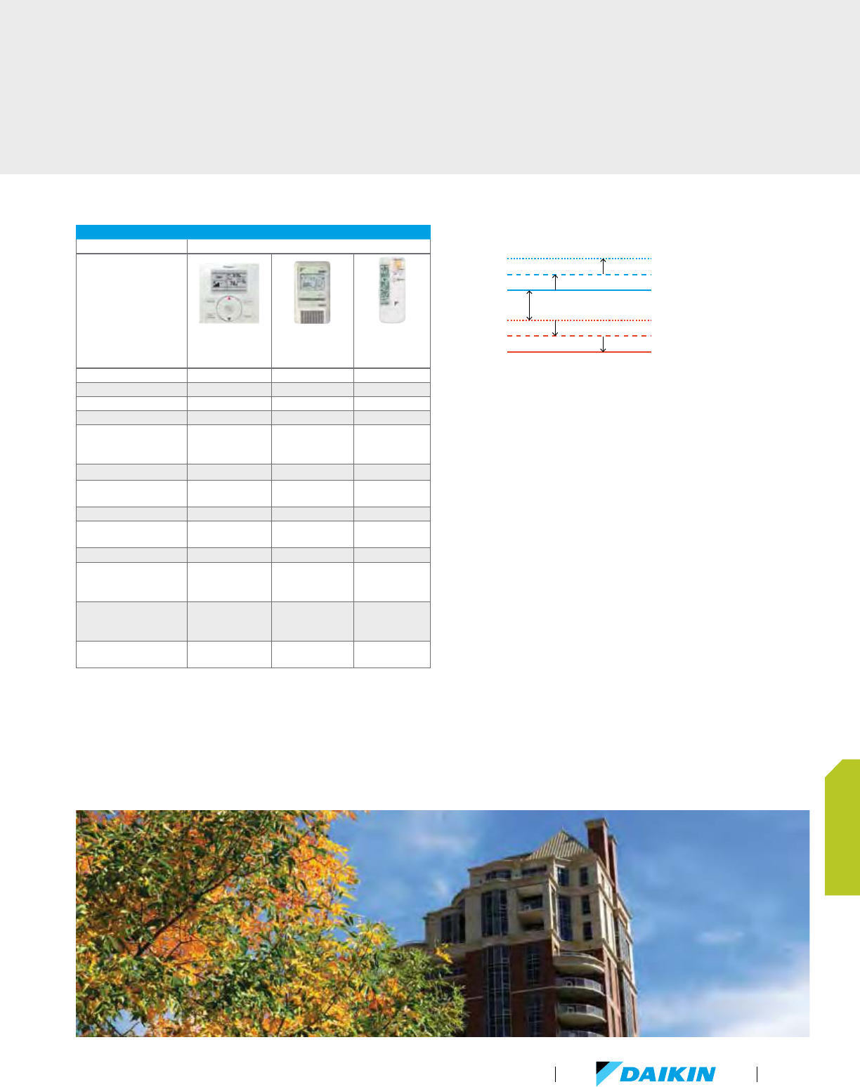
INDIVIDUAL CONTROL CAPABILITIES
System Capabilities Daikin Controls Options
BRC1E73
Navigation
Remote Controller
BRC2A71
Simplified Wired
Remote Controller
Wireless Remote
Controller (model
depends on unit)
Communications 2 Wire / DIII Net 2 Wire / DIII Net Infrared
°F/°C Selector
°F only °F only
Backlit LCD display
Room temperature display
Schedule and setback
capabilities (with Time
and Date display)
User restriction options
On/Off, Operation mode,
Setpoint, Fan speed
Louver position adjustment
Reports system
malfunctions
Space temperature sensor
Simultaneous operation
with Daikin multi-zone
controllers
Simultaneous operation
with BACnet
®
and
LonWorks
®
Group control capacity
Up to 16
indoor units
U
p t
o 16
indoor units
Up to 16
indoor units
Auto-changeover
Automatic changeover is available for Heat Pump system and
Heat Recovery systems. The setpoint for cooling and heating
are configurable with a minimum differential of 0 to 7°F or single
setpoint. The changeover is automatically controlled to happen
in either of the following two cases:
1. Case 1: Changeover at the primary changeover
temperature after the guard timer expires.
-
In default, the primary changeover setpoint is 1°F above
cooling setpoint or 1°F below heating setpoint, which is
configurable between 1°F – 4°F.
-
In default, the guard timer is 60 minutes, which is
selectable among 15, 30, 60 (default) or 90 minutes.
-
The initiation of guard timer is built in to help prevent
frequent changeover which may cause energy loss.
2. Case 2: Changeover at the secondary
changeover temperature.
-
In default, the secondary changeover temperature is 1°F
above the primary changeover temperature for cooling
or 1°F below the primary changeover temperature for
heating, which is configurable between 1°F – 4°F.
-
Case 2 will happen while the guard time is active in case 1.
Secondary
Primary
Cooling SP
Heating SP
Primary
Secondary
Surely Change to Cooling
Change to Cooling (with Guard Timer)
Change to Heating (with Guard Timer)
Surely Change to Heating
(1 to 4˚F)
(1 to 4˚F)
(1 to 4˚F)
Dual Sp. Min Differential (0 to 7˚F) or Single Sp.
(1 to 4˚F)
VRV Product Catalog
121
CONTROLS
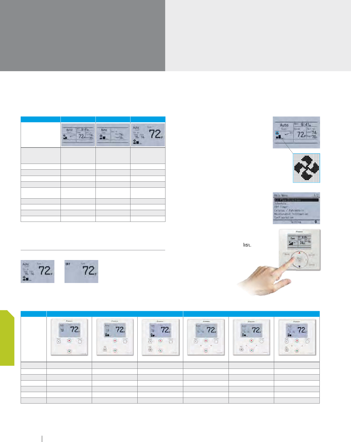
On/Off Display Option
Individual controllers
(continued)
Configurable Display Mode – Detailed, Standard, Simple
DISPLAY MODE DETAILED STANDARD SIMPLE NEW
Display Image
On/Off status on LED
(LED blinks when an
error occurs)
Mode
1
1
1
Setpoint (Dual/Single)
2
2
2
Room temperature
Fan speed
3
3
3
Airflow direction (when
a louver is available)
Day and Time
3
Status icon
3
3
Key lock icon
Error message
1
OFF can be displayed instead of the operation mode while the unit is turned off with the field setting
2
Can be removed from the display while the unit is turned off with a field setting
3
Can be removed from the display with a field setting
Clear display
Backlit display
-
Backlight helps operating
in dark rooms.
Dot matrix display
-
A combination of fine dots
enables various icons.
-
Large text display is easy to see.
Simple operation
Large buttons and arrow keys
-
Large buttons and arrow
keys enable easy operation.
Basic setting such as fan
speed and temperature can
be intuitively operated. For
other settings just select the
function from the menu list.
Optional Face Decals –
Hides unnecessary (locked/prohibited) buttons
USED WITH SINGLE SETPOINT MODE DUAL SETPOINT MODE
Model
BRC1E73RM BRC1E73RF BRC1E73RMF BRC1E73RM2 BRC1E73RF2 BRC1E73RMF2
On/Off
Mode
Fan
Up, Down
Left, Right
Menu/Ok
Cancel
BRC1E73 - Navigation Remote Controller (continued)
function from the menu list.
122 www.daikincomfort.com
CONTROLS

Daikin controls has advanced sensing functions so the operation can be
optimized for both occupied and unoccupied conditions.
VRV Product Catalog
123
CONTROLS
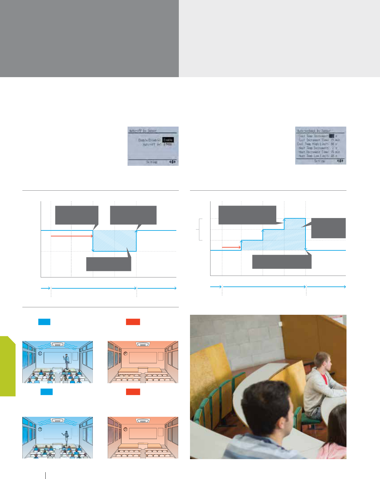
Individual controllers
(continued)
Energy saving
Automatic Off by occupancy sensor
-
The indoor unit will turn off
when it is determined that the
room is unoccupied after a
specified time has elapsed.
-
Can be used in conjunction
with the Auto Setback by sensor function
Auto-setback by sensor
-
The cooling and heating setpoints
will gradually relax (configurable)
internally when the room is
determined to be unoccupied.
-
The internal setpoint will return to the original
setpoint when room occupancy is detected.
Th
e first period starts and the air
cond
itioner starts the cooling operation.
1) 8
:
30 ON
ON
2) 10
:
00 OFF
OFF
In the second period, the classroom
is
unoccupied and the air conditioner stops.
Wh
en the third period starts,
operation
st
arts again.
After the third period, the classroom
becomes vacant again and the air
conditioner stops.
3)
13
:
00 ON
ON
4) 15
:
00 OFF
OFF
College classroom sample (a summer Monday case)
Automatic Off energy savings
BRC1E73 - Navigation Remote Controller (continued)
02 T (hrs)
On/Off
Cooling
Setpoint
(°F)
On
Auto Off
Occupied OccupiedUnoccupied
01530456
0T
(hr)
Occupied OccupiedUnoccupied
Unoccupied 2 hrs.
Indoor unit is turned
Off when no one
detected in space
Energy savings when
room is unoccupied
Occupant returns and
indoor unit required to
be turned on manually
74
76
78
80
Unoccupied
15 min.
Auto Setback Setpoint
Setback setpoint
increases 2°F every 15 min.
room is unoccupied
Energy savings
when room is
unoccupied
Occupied setpoint returned
when occupancy is detected
Automatic setback energy savings
02 T (hrs)
On/Off
Cooling
Setpoint
(°F)
On
Auto Off
Occupied OccupiedUnoccupied
015304560T (hr)
Occupied OccupiedUnoccupied
Unoccupied 2 hrs.
Indoor unit is turned
Off when no one
detected in space
Energy savings when
room is unoccupied
Occupant returns and
indoor unit required to
be turned on manually
74
76
78
80
Unoccupied
15 min.
Auto Setback Setpoint
Setback setpoint
increases 2°F every 15 min.
room is unoccupied
Energy savings
when room is
unoccupied
Occupied setpoint returned
when occupancy is detected
124 www.daikincomfort.com
CONTROLS
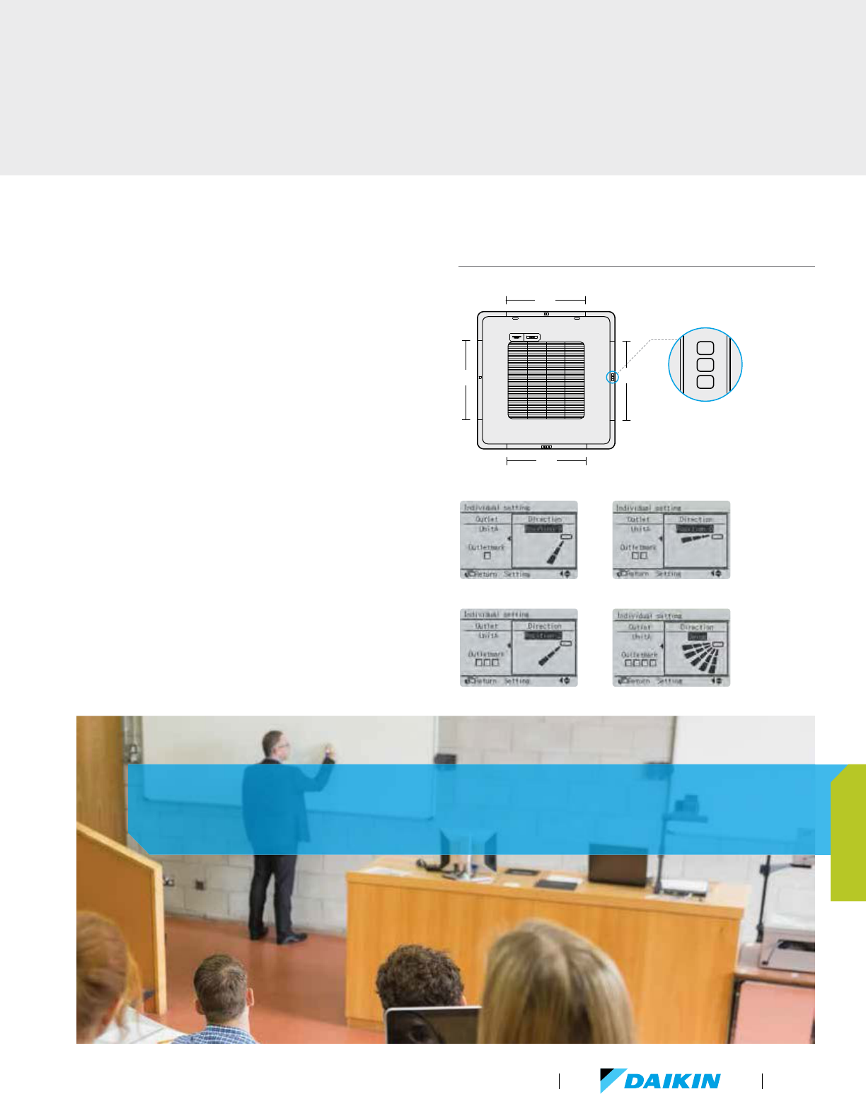
Comfort
Individual airflow direction
†
-
Airflow direction of each of the four air
outlets can be controlled individually.
-
(Positions 0 to 4, Swing, and No individual setting
are selectable.)
Auto airflow rate
†
-
Airflow rate is automatically controlled in accordance
with the difference between room temperature and
set temperature.
†
Only available for VRV 4-Way Flow Ceiling Suspended type
FXUQ-P series and Ceiling Mounted Cassette (Round Flow
with Sensing) type FXFQ-T series.
( 1 ) ( 2 )
( 3 ) ( 4 )
Outlet mark
( 2 )
( 4 )
( 1 )
( 3 )
Individual airflow direction
With 18 configurable airflow distribution patterns, the controls aid
efficiency and provides a comfortable environment.
VRV Product Catalog
125
CONTROLS
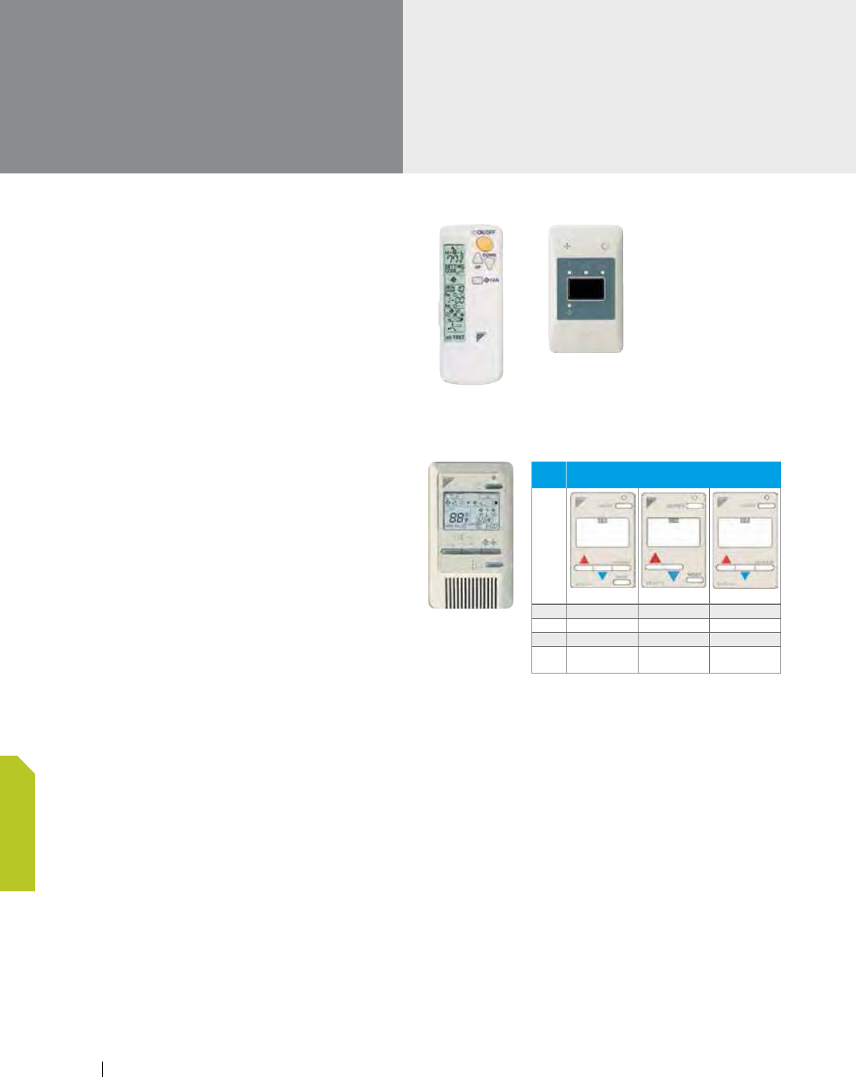
BRC4C82/BRC7E818/BRC7E83/BRC7E830
- Wireless Remote Controller
The same operation modes and settings as with
wired remote controllers are possible.
-
Individual airflow direction, auto airflow rate and sensing
sensor control can be set only via wired remote controller
BRC1E73. Cannot be set via other remote controllers.
A compact signal receiver unit (separate type) to
be mounted into a wall or ceiling is included.
-
The Ceiling Suspended and Wall Mount indoor units use
signal receivers that are mounted in the indoor unit.
BRC2A71 - Simplified Remote Controller
Economical controls solution
Suitable for use in hotels rooms, hallways,
reception areas and conference rooms
Features
-
On/Off
-
Operation mode
-
Single setpoint
-
Fan speed adjustment
-
Can be used with the optional remote temperature sensor
for sensing room temperature
Wireless remote
controller
Signal receiver unit
(separate type)
Wireless remote controller
and signal receiver unit are
sold as a set.
Individual controllers
(continued)
Simplified remote
controller
USED
WITH
FACE PLATE OPTIONS
Model
BRC2A71RS
BRC2A71R
BRC2A71RU
On/Off
Mode
Fan
Up,
Down
126 www.daikincomfort.com
CONTROLS
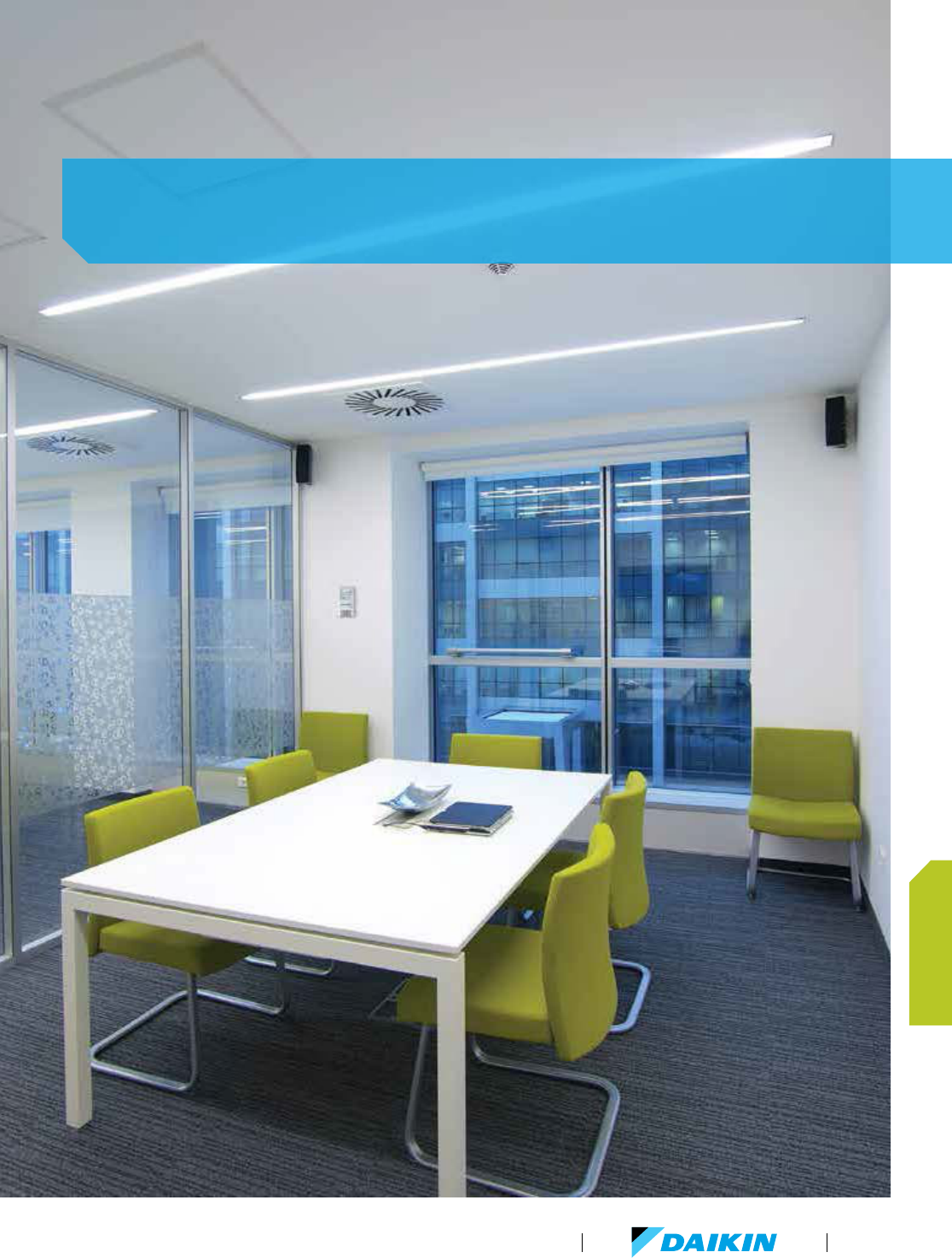
By providing individual zone control, the occupant of each space has the
ability to set the room temperature where they feel most comfortable.
VRV Product Catalog
127
CONTROLS
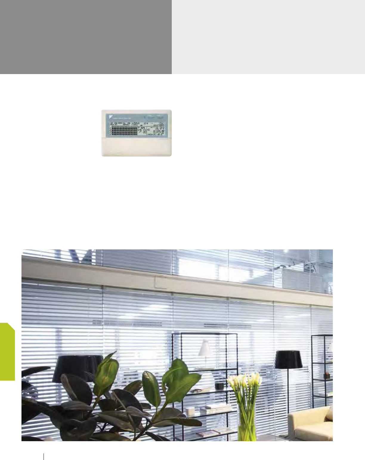
Centralized controllers
DCS302C71 - Central Remote Controller
Maximum 64 groups (zones) of
indoor units can be controlled
individually.
Maximum 64 groups (128
indoor units) controllable
Maximum 128 groups
(128 indoor units) are
controllable by using 2 central remote controllers,
which can control from 2 different places.
Zone control
Malfunction code display
Maximum wiring length 3280 ft. (Total: 6560 ft.)
Connectable with Unified ON/OFF controller,
schedule timer and BMS system
Airflow volume and direction can be controlled
individually for indoor units in each group operation.
Ventilation volume and mode can be controlled
for Energy Recovery Ventilator.
Up to 4 ON/OFF pairs can be set per day
by connecting a schedule timer.
128 www.daikincomfort.com
CONTROLS
DCS301C71 - Unified On/Off Controller
Maximum 16 groups of indoor units
can be operated simultaneously/
individually.
Maximum 16 groups (128
indoor units) controllable
Operating status indication
(Normal operation, Alarm)
Centralized control indication
Maximum wiring length 3280 ft. (total: 6560 ft.)
Compact size casing (thickness: 0.63in)
Connectable with Central Remote Controller,
Schedule timer and BMS system
DST301BA61 - Schedule Timer
Maximum 128 indoor units can be
operated as programmed schedule.
Maximum 128 indoor
units controllable
When used in combination with
a central remote controller, a
maximum of 8 weekly schedule
patterns can be set, while
the central controller can be used to select desired
zones. Up to 2 ON/OFF pairs can be set per day.
Maximum 48 hours back up power supply
Maximum wiring length 3280 ft. (total: 6560 ft.)
Compact size casing (thickness: 0.63in)
Connectable with Central Remote Controller,
Unified ON/OFF controller and BMS system
The Central Controllers can monitor and control indoor units by either
group or zone. Their easy-to-read liquid crystal displays (LCDs) allow you
to orchestrate and monitor temperature, time, and airflow volume, etc.
across your entire system at the touch of button.
VRV Product Catalog
129
CONTROLS
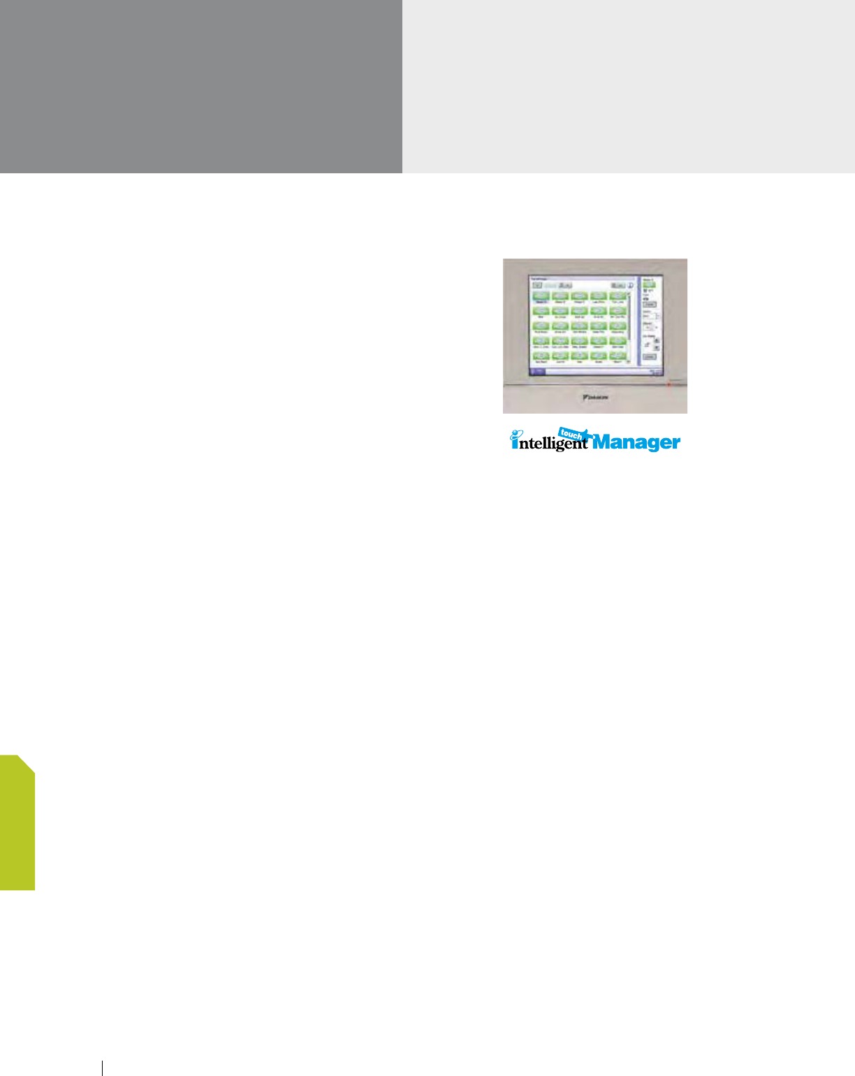
Advanced multi-zone
controllers
DCM601A71 - intelligent Touch Manager (iTM)
One for all
The intelligent Touch Manager (iTM) is an advanced multi-zone
controller that provides the most cost-effective way to control
and monitor the Daikin VRV system.
Centralized and Advanced VRV Control
Up to 64 Indoor Unit Groups (128 actual Indoor Units) can be
monitored and controlled with individual Cool and Heat Setpoints,
Setpoint Range Limitation, Setback Setpoints, and Auto
changeover to meet your expectations and project requirements.
Up to 512 Indoor Unit Groups (1024 actual Indoor Units) can be
monitored and controlled with the addition of up to 7 optional
iTM Plus Adapters.
Ancillary Equipment Control
Integrates and/or interlocks sensors, switches, dampers, fans,
pumps, and lighting with Daikin Indoor Units.
Web Access and Alert E-mail
Allows daily remote monitoring and control with the Web/E-mail
function that can be accessed via the facility’s Local Area Network
or your Internet connection. Sends Error E-mail to mobile devices
with the Web/E-mail function.
Tenant Billing
Determines energy consumption of shared condensing units
based upon tenant (Indoor Unit) demand with optional PPD
Software option (DCM002A71).
Features
10.4" LCD touch screen, USB drive
Advanced, scalable and cost-effective management system
-
Up to 650 points (max 512 indoor unit groups
(1024 indoor units)
-
Floor plan layout view
Functions
Dual setpoints or Single setpoint in Occ or Setback in Unocc
Setpoint Range Limitation
Scheduling (7 day, Weekday-Weekend,
Weekday-Saturday-Sunday, Everyday)
Optimum Start and Timed Override
Advanced Auto changeover
-
Applicable to both VRV Heat Pump and Heat
Recovery systems
-
Fixed, Individual, Average and Vote methods
Web Accessibility and Alert Email (standardized)
-
All screen views and configuration menus can be accessed
through Web
WAGO I/O
-
Monitor and control 3rd party equipment with Di, Do and
Ai signals
-
Up to 512 management points
-
Interlock function with indoor units and ancillary equipment
iTM BACnet
®
Client (option)
-
Enabling the BACnet Client option the iTM uses the
BACnet protocol BACnet IP
-
Allows for full monitoring and control of 3rd party
BACnet capable equipment
-
Up to 512 BACnet management points
130 www.daikincomfort.com
CONTROLS
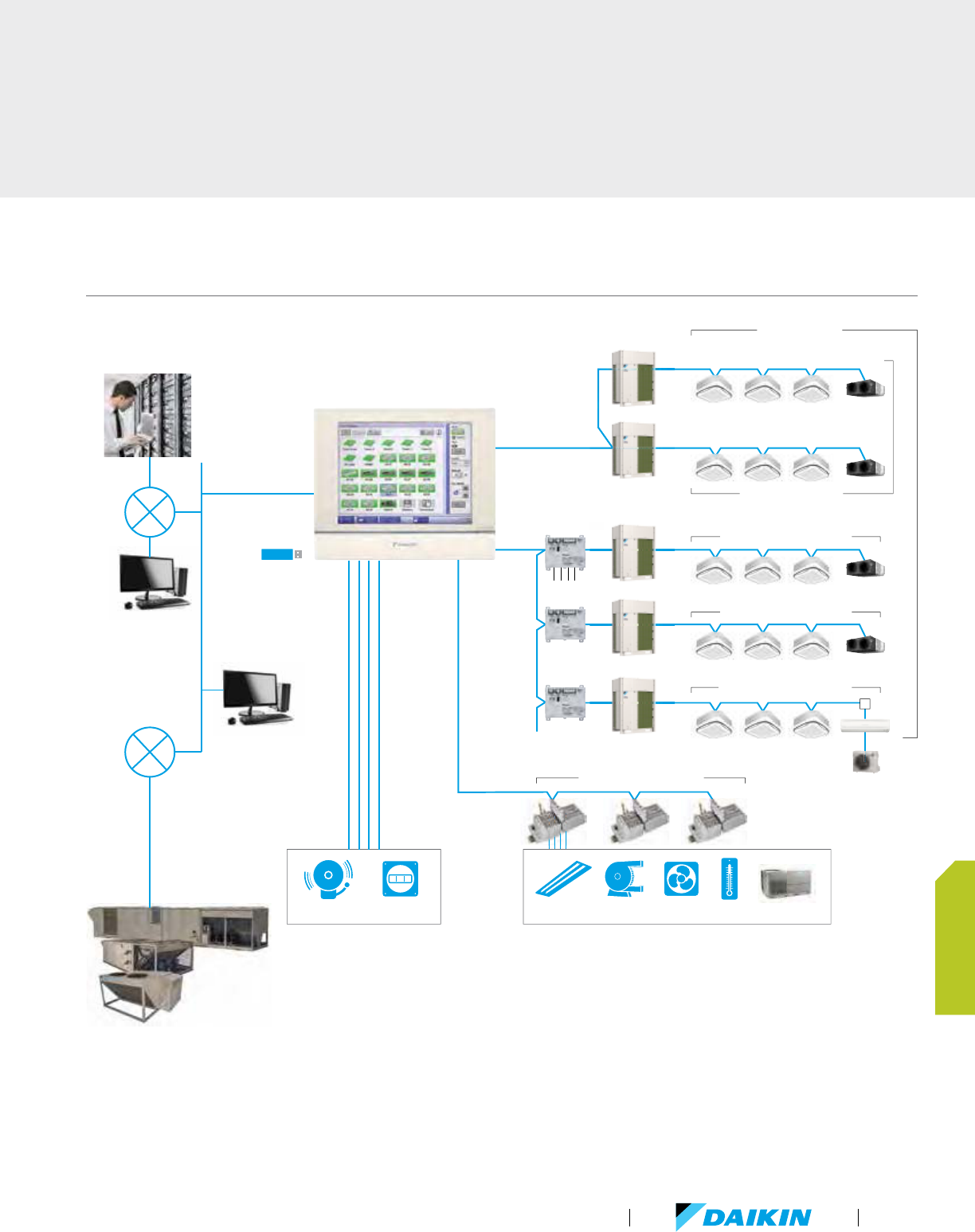
iTM system overview
Lighting
Pump FanSensorAUH, RTU
Fire alarmkWh meter
WAGO I/O up to 30 nodes
Up to 7 adapters
Di/Pi port
iTM Plus Adapter
DIII-NET
Max. 64 indoor unit groups
Max. 64 indoor unit groups
Max. 64 indoor unit groups
Up to 512 groups
(1024 indoor units)
one DIII-NET system
Max. 64 indoor unit groups (128 indoor units)
te
r
KRP928
Adapter
Di/Pi port
USB 2.0
flash drive
100Mbps
ethernet
Web access
via Internet
Web access
via LAN
iTM BACnet
®
Client
(BACnet IP)
D-Net
Up to 650 management points
Dedicated Outside Air Supply
(DOAS)
VRV Product Catalog
131
CONTROLS
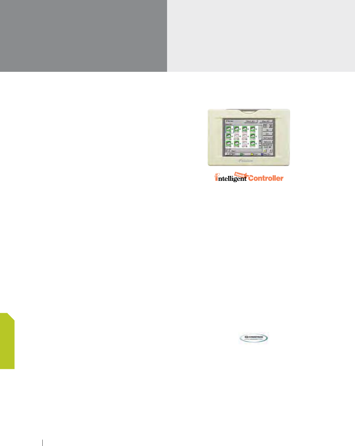
DCS601C71 - intelligent Touch Controller (iTC)
Centralized and Advanced VRV Control
Up to 64 Indoor Unit Groups (128 actual Indoor Units) can be
monitored and controlled with individual Cool and Heat Setpoints,
Setpoint Range Limitation, Setback Setpoints, and Auto
changeover to meet your expectations and project requirements.
Up to 128 Indoor Unit Groups (256 actual Indoor Units) can
be monitored and controlled with the addition of the Optional
DIII-Net Plus Adapter (DCS601A72).
Ancillary Equipment Control
Integrates and/or interlocks sensors, switches, dampers, fans,
pumps, and lighting with Daikin Indoor Units.
Web Access and Alert E-mail
Allows daily remote monitoring and control with the Web/E-mail
Software option that can be accessed via the facility’s Local
Area Network or your Internet connection. Sends Error
E-mail to mobile devices with the optional Web/E-mail Software
option (DCS004A71).
Tenant Billing
Determines energy consumption of shared condensing units
based upon tenant (Indoor Unit) demand with optional PPD
Software option (DCS002A71).
Features
Color LCD touch panel icon display
Simplified engineering
Multi language (English, French, Italian, German, Spanish)
Yearly schedule
Independent dual or single setpoints for
occupied and setback operation
Auto heat/cool change-over
Enhanced history function
Simple Interlock Function
Doubling of number of connectable indoor units
by adding a DIII-NET Plus Adapter (option)
Functions
Advanced Zone Level Control
-
Add advanced temperature control functions from a single
multi-zone controller
Independent Cool, Heat, and Setback Setpoints
Advanced Auto changeover
-
Applicable to both VRV Heat Pump and Heat
Recovery systems
-
Fixed, Individual, and Average methods
Scheduling (7 day, Weekday-Weekend,
Weekday-Saturday-Sunday)
Centralized Control with three different view styles
Setpoint Range Limit
Simple interlock
Web server (option)
Alarm E-mail (option)
PPD (tenant billing option)
HTTP interface (option)
Advanced multi-zone
controllers (continued)
132 www.daikincomfort.com
CONTROLS
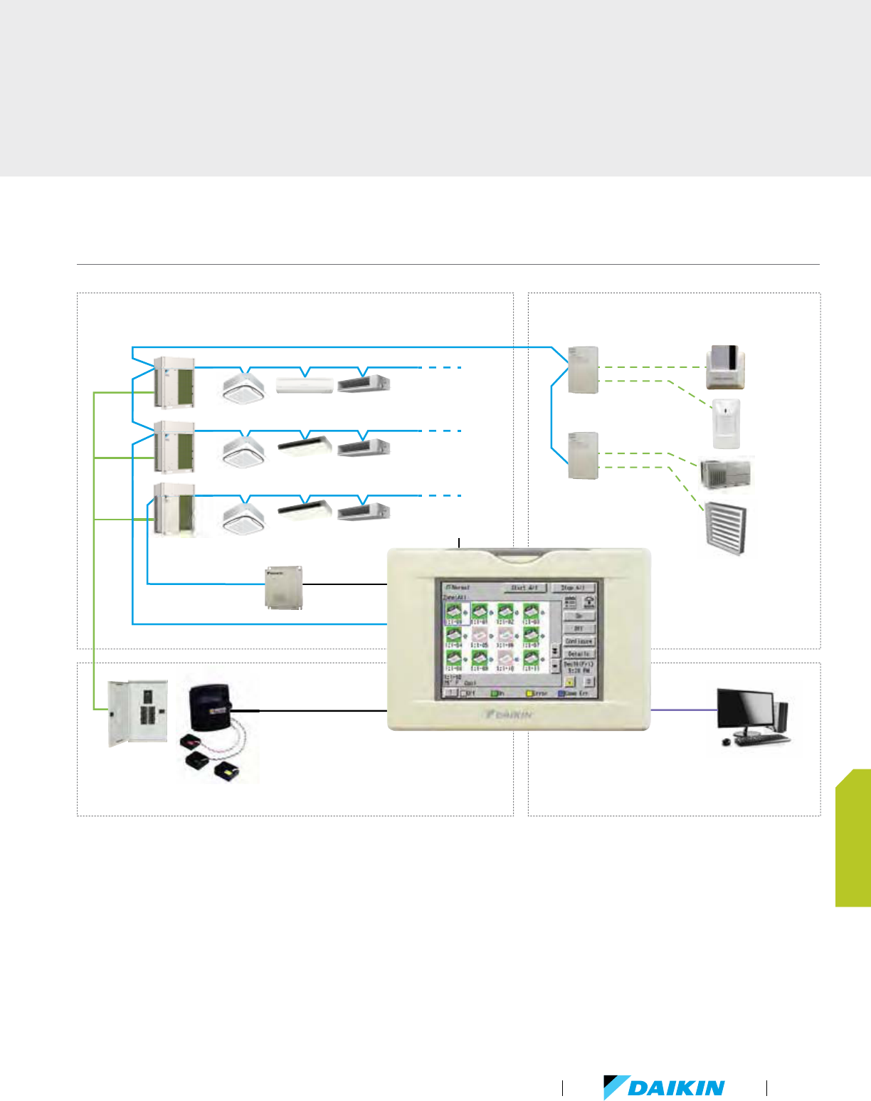
Emergency/forced
shutdown
DIII-Net Plus
Adapter
Pulse input
Digital input
(DI) unit
Digital input/output
(DIO) unit
Key card
Occupancy
sensor
Ancillary
equipment
Damper
Ethernet
PC
Energy meter
Power Proportional Distribution (PPD)
- apportions total outdoor unit power consumption
among indoor units with optional PPD software
Web access and alert e-mail
Ancillary equipment control
Centralized and advanced VRV control
Tenant power consumption
D
iTC system overview
VRV Product Catalog
133
CONTROLS
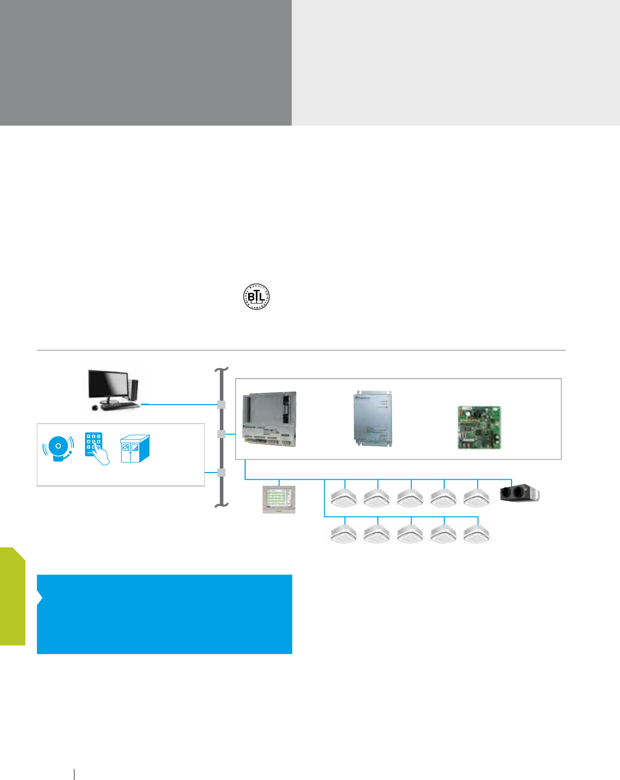
Open protocol
interfaces
Interface for BACnet
®
, LonWorks
®
and Modbus
BACnet
®
features
BACnet
®
: Building Automation and Control Networks
-
Standard open protocol based on ANSI/ASHREA
Standard 135
Monitor/Control indoor unit’s points
Monitor/Control up to 256 indoor units
groups (512 indoor units)
Certified by BACnet Testing Laboratories (BTL)
Manage up to 4 DIII-Net systems
-
Option Board (DAM411B51) required
LonWorks
®
features
BMS interface based on LonTalk
®
Gateway between Daikin DIII-Net and
BMS LonTalk
®
work station
-
Manages up to 64 indoor unit groups (128 indoor units)
with network variables for each group
-
Manages 1 DIII-Net system
Lon Interface communicates over twisted pair wire
External Interface File (XIF) documents device
information available at www.daikinac.com
®
Ethernet
Central Controller
Please contact Daikin for compatibility with BMS system
Security Power supply facilityFire alarm
Lift
Pump
Lighting, etc.
BMS
VRV System
Energy recovery
ventilator
B
DMS502B71
†
(Interface for
use in BACnet
®
)
DMS504C71
‡
(Interface for use
in LonWorks
®
)
DTA116A51
(Interface for use
in Modbus)
†
BACnet
®
is a registered trademark of American Society
of Heating, Refrigerating and Air-Conditioning
Engineers (ASHRAE).
‡
LonWorks
®
is a trademark of Echelon Corporation
registered in the United States and other countries.
BACnet/LonWorks system overview
Daikin's BACnet, Lonworks and
Modbus interface units provides
control for all VRV systems.
Modbus features
BMS interface based on Modbus (RS485)
Gateway between Daikin DIII-Net and
BMS Modbus workstation
-
Manages up to 16 VRV indoor units connected to up to
2 outdoor units
Modbus interface communicates via Modbus RTU
134 www.daikincomfort.com
CONTROLS
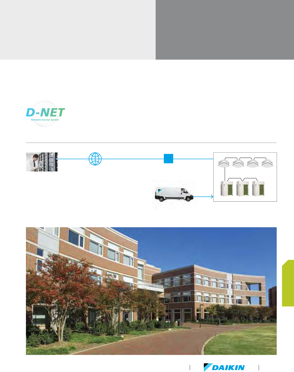
VRV monitoring
services
D-NET Air Conditioning Network Service System
Save energy. Protect your equipment investment. Maintain comfort levels.
D-NET connects your equipment to our
monitoring center over the web. We
continually monitor more than 80 data
points in your equipment
*
, so we know
exactly how your systems are performing.
We also monitor outside conditions from
more than 400 locations across the United States and Canada,
so we know what kind of weather you’re up against. Putting this
information together, we know if your systems can be optimized
remotely to reduce your energy consumption.
I/F unit *
Internet
Malfunction information by e-mail
Automatic data transfer
ACC Center
(Air conditioning Control Center)
* For an I/F unit, one of the following can be selected: Local Controlle
r,
intelligent Touch Controller, or intelligent touch Manager.
Local contractors
D-NET Air Conditioing Network Service System overview
VRV Product Catalog
135
CONTROLS

Option list
Individual zone controllers
ITEM MODEL NO. FUNCTION
Navigation Remote Controller BRC1E73 Programmable zone controller
Wireless Remote Controller
BRC4C82
BRC7C812
BRC7E818
BRC7E83
BRC7E830
Hand-held zone controller with infrared receiver kit
Simplified Remote Controller BRC2A71 Non-programmable zone controller
Centralized controllers
ITEM MODEL NO. FUNCTION
Central remote controller DCS302C71
Up to 64 groups of indoor units (128 units) can be connected, and ON/OFF, temperature setting and monitoring can be accomplished
individually or simultaneously. Connect up to 2 controller in one system.
Unified ON/OFF controller DCS301C71
Up to 16 groups of indoor units (128 units) can be turned, ON/OFF individually or simultaneously, and operation and malfunction status can be
displayed. Can be used in combination with up to 8 controllers.
Schedule Timer DST301BA61 Weekly schedule can be programmed by the controller for up to 64 groups of indoor units (128 units). Can turn units ON/OFF twice per day.
Advanced multi-zone controllers
ITEM MODEL NO. FUNCTION
intelligent Touch
Controller
Basic Hardware
intelligent Touch
Controller
DCS601C71
Air-Conditioning management system that can control up to 64 groups (10
outdoor units).
Optional
Hardware
DIII-Net plus
Adapter
DCS601C72 Additional 64 groups (10 outdoor units) are possible.
Software
iTC PPD Option DCS002A71
Power consumption of indoor units are calculated based on operation status of
the indoor unit and outdoor unit power consumption measured by kWh meter.
iTC Web Option DCS004A71
Provides access to ITC via web browser with PC. Error Email sent when errors
occur.
iTC HTTP Interface Option DCS007A51 Interface to home automation system certified with Crestron home automation
intelligent Touch
Manager
Basic Hardware intelligent Touch Manager DCM601A71
Air-conditioning management system that can be controlled by
touch screen or web browser to monitor and control up to 64 groups (10 outdoor
units).
Optional
Hardware iTM Plus Adapter DCM601A72
Maximum 7 iTM Plus Adapters can be connected to intelligent Touch Manager.
Each iTM Plus Adapter can add and additional 64 groups
(10 outdoor units)
Software iTM PPD Option DCM002A71
Power consumption of indoor units are calculated based on operation status of
the indoor unit and outdoor unit power consumption measured by kWh meter.
Open protocol interface
ITEM MODEL NO. FUNCTION
Interface for use in BACnet
®
DMS502B71
Interface unit to allow communications between VRV and BMS.
Operation and monitoring of air-conditioning systems through BACnet
®
communication.
Optional DIII board DAM411B51 Expansion kit, installed on DMS502B71, to provide 2 more DIII-NET communication ports. Not usable independently.
Interface for use in LONWORKS
®
DMS504C71
Interface unit to allow communications between VRV and BMS.
Operation and monitoring of air-conditioning systems through LonWorks
®
communication
Interface for use in Modbus DTA116A51
Use of the Modbus protocol enables the connection of the VRV system with a variety of home automation and BMS systems
from other manufacturers.
136 www.daikincomfort.com
CONTROLS
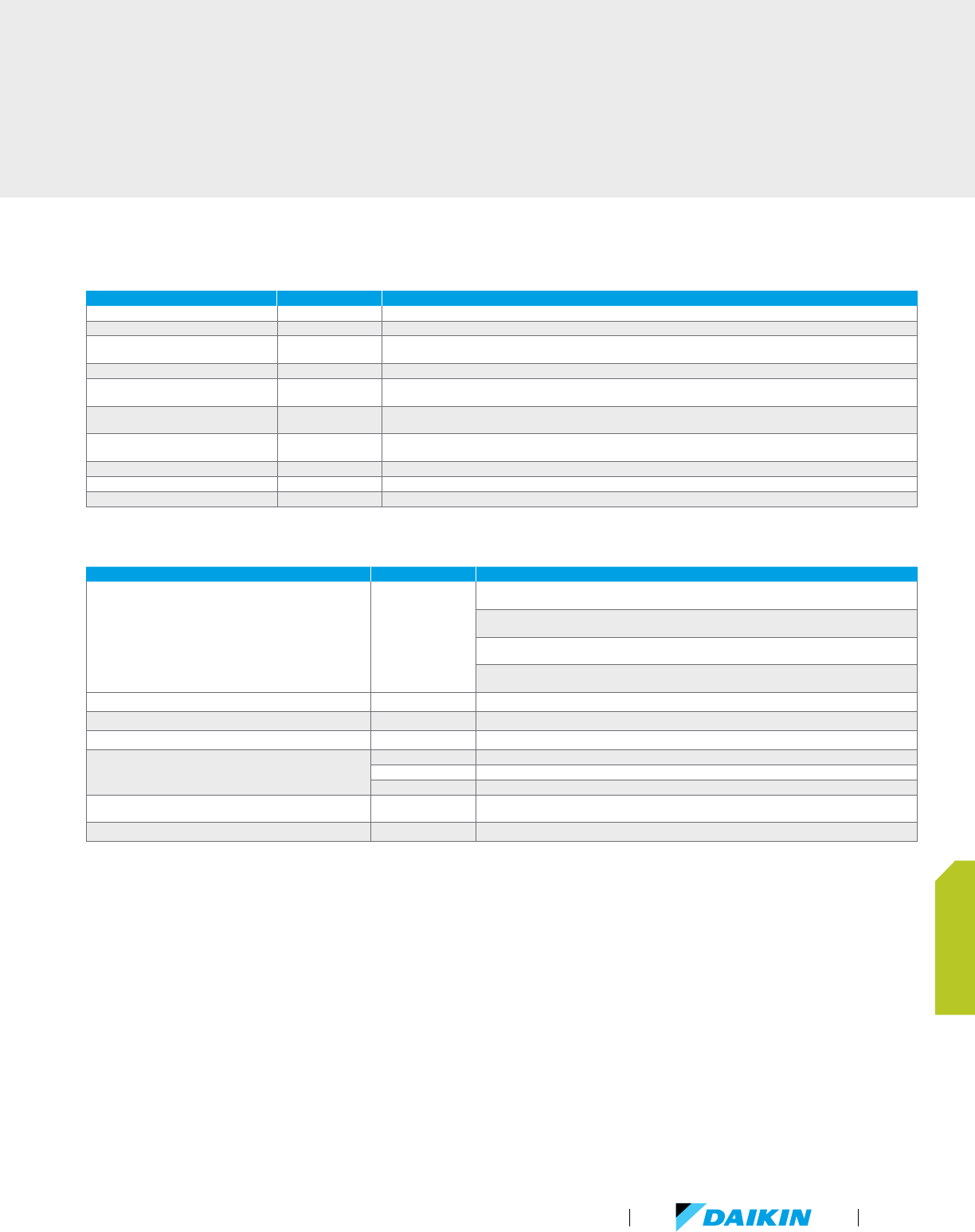
Adapters
ITEM MODEL NO. FUNCTION
Digital Input (Di) Unit DEC101A51-US2 Monitor On/Off and Error status of ancillary equipment
Digital Input/Output (Dio) Unit DEC102A51-US2 Monitor and control of ancillary equipment
DIII-Net Expander Adapter DTA109A51
Apply to increase the number of outdoor units (up to another 10) connected in one DIII-Net system. Apply to overcome communication
errors in electrically noisy environments.
Unification Adapter for Computerized Control DCS302A72 Turn On/Off the system from a central panel through Centralized Controller or iTouch Controller. Monitor On/Off and Error Status.
External control Adapter
for Outdoor Unit
DTA104A53/61/62
Unified changeover of Cool/Heat mode. To change the mode of several outdoor units by one remote controller. Demand Control. Low
Noise Control: -2 to 3 dB of outdoor unit
Group Control Adapter KRP4A71/72/73/74
Turn On/Off Remote Control Group. Change setpoint (with resistance interface 0-135 ohm). Monitor On/Off and
Error status
ABC Terminal Kit BRP2A81
Remotely manage the operating mode of the heat pump system. Integration point for ambient thermostats to
engage lock-out
Wiring Adapter KRP1C74/75 Thermo-on status. Fan status. AUX heater output. Humidifier output
RA Interface Adapter for DIII-Net Use KRP928B2S Mini-split can be controlled through DIII-NET
RA PCB Adapter for Time Clock KRP413A1S Remotely Start / Stop for mini-split indoor units
WAGO
ITEM MODEL NO. FUNCTION
Basic Kit
(required for each Node)
51291052
Bus Coupler
MODBUS (RS485) Communication, 24VDC input
E
nd Module
To loop the internal bus
Connector
D-Sub male connector: 9 pin, 2 horizontal wire entries, one input and one output
24 VDC Power Supply
Input voltage 110 – 240VAC, output voltage 24VDC @ 2.5A
2 Channel Digital Input 750-400 2 Channel, DC 24V, 3.0ms, high-side switching
4 Channel Digital Input 750-432 4 Channel, DC 24V, 3.0ms, low-side switching, w/(+) terminal
2 Channel Digital Output 750-513/000-001 2 Channel, AC 230V, DC 30V, AC/DC 2A, isolated outputs
2 Channel Analog Input
750-454 2 Channel, 4 - 20 mA, Differential Inputs
750-479 2 Channel, DC ± 10 V, Differential measurement input
750-461/020-000 2 Channel, NTC 20K Ohm Resistance
24 VDC Power Supply (Passive)
(required for every 32 contact points used)
750-602 24 VDC Passive
Wiring Field Supplied 2 conductor 24 – 18 AWG stranded
VRV Product Catalog
137
CONTROLS

www.daikincomfort.com138
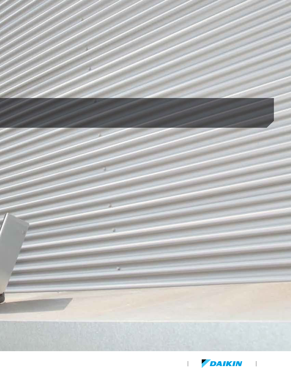
VRV Product Catalog
139
Support and tools

SUPPORT & TOOLS
www.daikincomfort.com140
Support and tools
Daikin provides multiple tools to aid the design,
selection, analysis, submission, and general
support for its line up of ductless, rooftop, light
commercial split and specifically for the full line
of Daikin VRV systems.
The tools have been designed to be simple to use, easily
accessible and to address the various considerations and steps
in the evolution of a residential or commercial project, aimed at
helping the architect, consulting engineer, contractor, installation
technician, and service company to enhance workflows and
general project execution.
Daikin’s array of software and support tools are designed to streamline all
stages of project design, application, installation and service/maintenance.
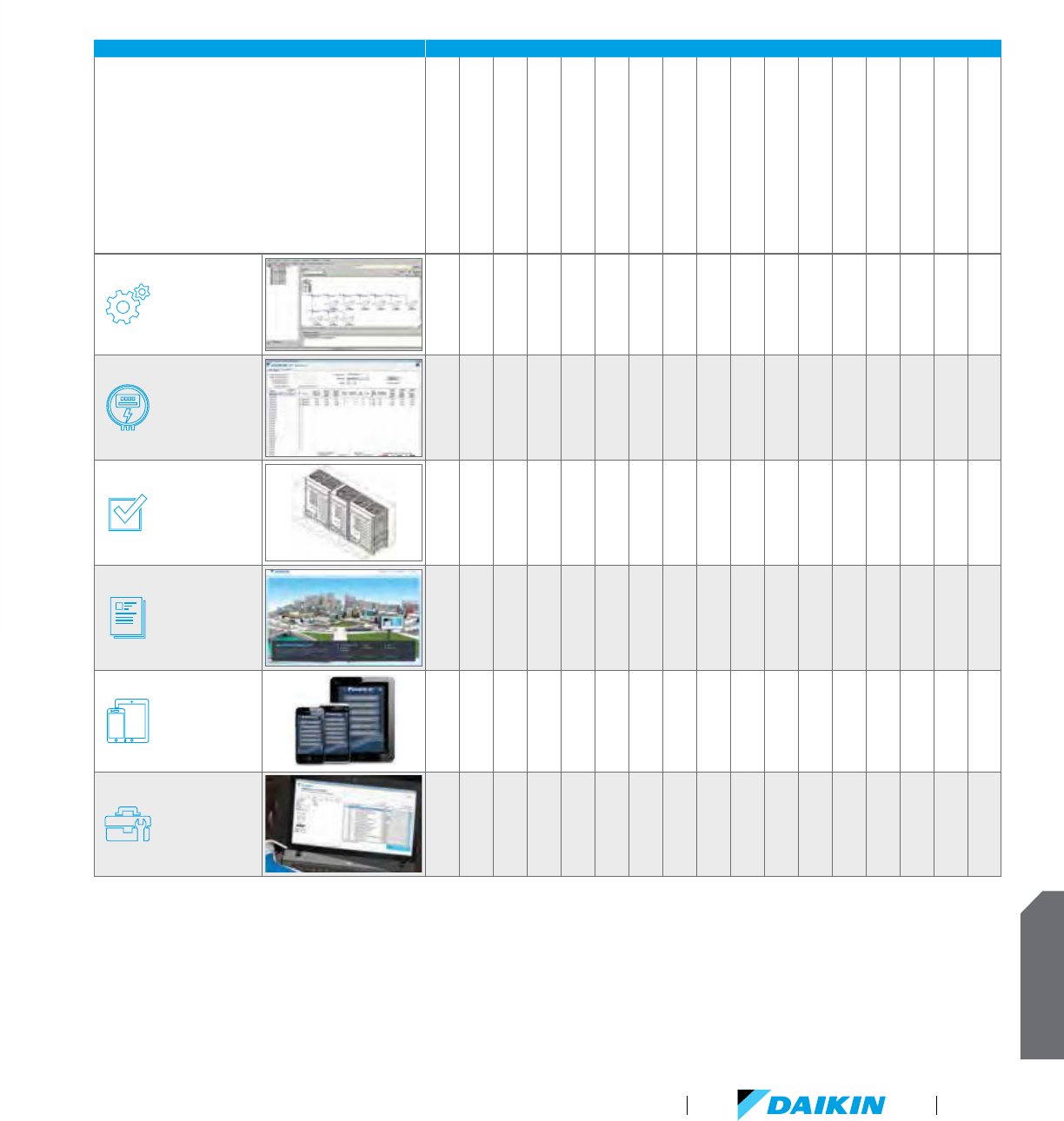
SUPPORT & TOOLS
VRV Product Catalog
141
Daikin VRV support and tools overview
CATEGORIES TOOLS
Xpress
W-III Xpress
Ventilation Xpress
Controls Configurator
Online Energy Calculator
IES-VE Daikin VRV plug-in
Performance curves for third-party
energy simulation Programs
CAD drawings
Revit models
Reference Charge Calculator
Ventilation Rate Calculator
Daikin City (including Guide Specs,
IOMS etc.)
Daikin eQuip application
Dr. Daikin
VRV Configurator
Service Checker
Online Spare Parts Bank
Selection
Energy screening
and simulation
Design and
verification
Online and tablet
reference (spec,
data, submittal)
Smartphone and
mobile reference
After sales
and service
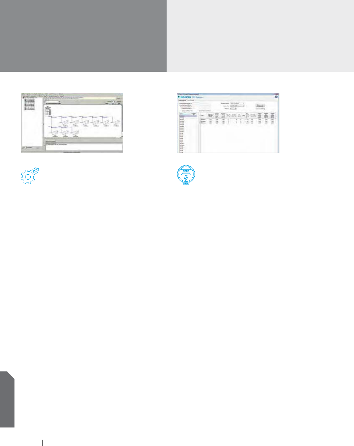
www.daikincomfort.com142
SUPPORT & TOOLS
Support and tools
Selection software
A key tool for Reps, Consulting Engineers and Contractors to
use is the suite of Xpress selection software. This tool is a
windows based EXE file designed to provide quick, easy and
above all accurate selections of VRV systems and ventilation
devices. Inputs can be customized to meet a variety of project
needs and has the following features and benefits:
Fully array of software configuration settings
Select and customize indoor unit types
with options/accessories
Optimize condensing unit selections
based on block load characteristics
Define pipe sizes and lengths and both local
and centralized wiring schemes
Define and generate selection reports in Word
(RTF), Excel (CSV), or CAD (DXF) formats
As controls for VRF systems become much more sophisticated
at both a zone and building level, ensuring the full array of
features are captured, Daikin has developed a simple controls
configurator tool allowing the consulting engineer or contractor
to capture all of the features that are needed to be utilized with
the suite of controls products from Daikin so to ensure that
the commissioning engineer can then set-up and configure the
system appropriately at start up.
Energy screening and simulation tools
With the continued trend in looking at building costs beyond just
the 1st cost, accurately screening or simulating the performance
of systems in buildings at the conceptual stage is more important
than ever. Daikin recognizes this need and has developed a variety
of support tools for this purpose.
Online VRV energy calculator
Easy access and registration via online.
Free of charge and easy to use.
Allows for a semi-dynamic energy screening to be completed
for VRV only. Provides useful information such as part load
curves, estimated annualized operating costs etc.
IES-VE plug-in for Daikin VRV
One of the leading Energy Simulation programs in Europe
is now gaining awareness and a growing user-base in
North America.
With the Daikin VRV plug in for IES-VE you can take advantage
of the enhanced energy simulation capabilities with the IES
platform and combine in a fully validated modeling methodology
for Daikin VRV systems including the innovative and energy
saving “VRT” function. The results of the IES-VE simulations
can be utilized for LEED, California Title 24 and other regulatory
energy simulation requirements.
Performance curve/plug-ins
for 3rd party modeling software
Daikin have developed curves, instructions and sample building
files for a variety of other 3rd party energy simulation software
programs such as:
-
eQuest - Energy Pro
-
Trace 700 - Energy Plus (VRV HP only)
-
HAP
Xpress IES-VE plug-in for Daikin VRV
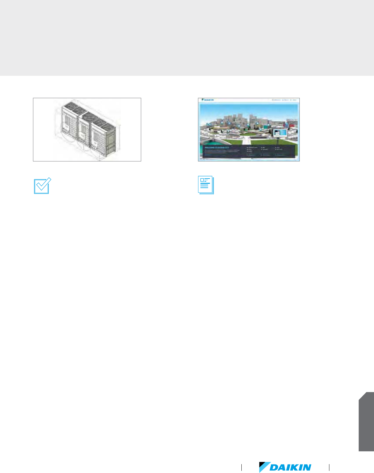
VRV Product Catalog
143
SUPPORT & TOOLS
Design and verification
Equipment Selection and Energy Simulation only reflect the
early stages of a project evolution. At Daikin we recognize the
importance of additionally providing resources to the Engineer
and Architect community as well as contractors as follows:
CAD files for all products in multiple
formats (DWG and DXF)
Revit files for BIM architecture for all products
Refrigerant Charge Calculator
-
Quick check of the total refrigerant charge in a VRV System
based on applied pipe-lengths and combination ratio’s etc
-
Quick check of the minimum room volume (occupied space)
that system charge can be utilized in per ASHRAE Standard
15-2010 and ASHRAE Standard 34-2010.
Ventilation Rate Calculator
-
Easy to use calculator to determine ventilation rates required
for different room sizes and applications in accordance with
ASHRAE Standard 62.1-2013.
Online and tablet reference material
Daikin City serves as the multi-functional portal for all disciplines
interested in or already using Daikin products and technologies for
a project. More than just a typical website, Daikin City provides:
Energy-saving characteristics of VRV systems in various
vertical market buildings
Product videos and feature summaries via the
communications center
A fully stocked library of information simply arranged for ease
of finding any piece of Daikin information you may need such
as IOM’s, brochures, engineering data, and application guides
etc (registration required).
Easy access to the suite of sales tools that Daikin offer
(registration required).
An easy to use product specification library to quickly verify
any spec item required, or to generate a submittal data sheet,
guide spec or confirmation of the available accessories and
options for a specific product (registration required).
Revit
www.DaikinCity.com

www.daikincomfort.com144
SUPPORT & TOOLS
Smartphone and mobile reference
With the Daikin eQuip application, available for both iOS
devices and Android devices, you can have the power of
all Daikin product information and support material readily
accessible on your mobile device or tablet.
For rapid resolution to a system with an error code, or general
troubleshooting needs, the Dr. Daikin tool is a helpful and
quick reference tool that works via a standard desktop, tablet
or smartphone and even SMS. When you need to understand
or isolate the scope of one of Daikin’s diagnostic codes, enter
the code into the Dr. Daikin resource and automatically the
tool will provide feedback of what the diagnostic code refers
to and straightforward guidance on how to address the code.
Visit www.drdaikin.com for further information.
Daikin eQuip application www.DrDaikin.com
Support and tools
(continued)
Daikin's tools and support enables consulting engineers, building owners
and installers to optimize the life cycle cost of the VRV systems.
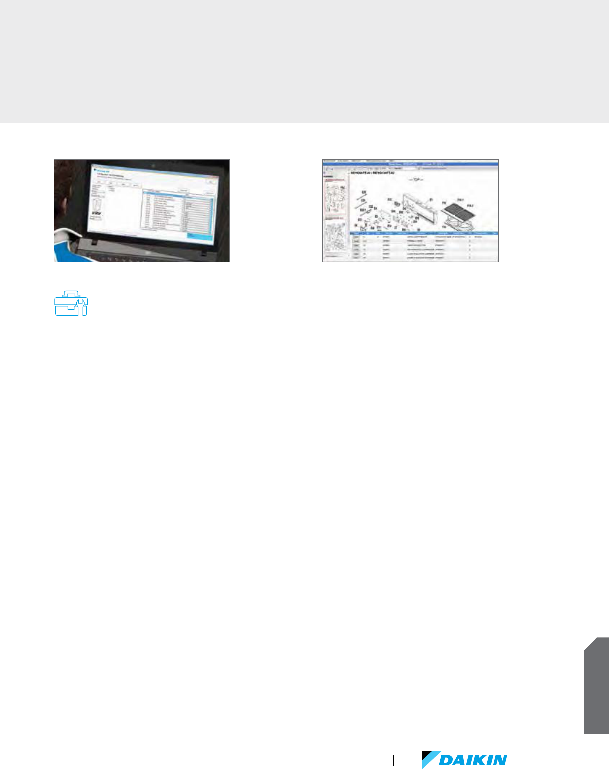
VRV Product Catalog
145
SUPPORT & TOOLS
After sales and service
With a strong commitment to sales tools to help design and apply
the product is equally supported with a strong commitment on
after-sales and service tools aimed at the service contractor or
maintenance technician.
Daikin VRV Configurator is a PC based software tool that
allows an installing contractor to “set-up” the operating
parameters and field settings of the VRV IV outdoor units
off-site and then use a handy USB connection to upload those
settings during the commissioning process. This helps save
time and ensure that projects with multiple systems can be set
up correctly and error free. The Configurator tool also allows
for up to 48hrs of operation data from an installed system to
be downloaded to a laptop computer for analysis if needed.
Daikin VRV Service Checker is a PC based software tool
that facilitates a connection to the system and monitors all
components of the system including temperatures, pressures,
compressor and fan speeds, and may other items and can be
utilized to understand operational trends with the system and
what is happening in the system at a specific time. This tool
is very helpful when troubleshooting a system in the event of
error or diagnostic notification.
Daikin’s online spare parts databank (registration required)
is an easy to use graphically driven means of identifying what
spare or replacement part might be needed during the life
cycle of the VRV equipment. Using this resource will help you
identify the part number, applicable model, any alternative part
options, and the availability of the part both locally and globally.
Daikin University offers Daikin's customers a variety of quality
training programs designed to provide the tools and resources
needed for our customers to be successful.
-
Our courses are designed by training professionals
around specific objectives based on industry needs
and job task analysis. We offer a choice of instructional
settings based on the program goals and our students’
needs including: online/on-demand web-based training,
instructor led webinars, onsite training, and instructor-led
classroom training at one of our many Daikin Authorized
training facilities.
Daikin VRV Configurator Daikin’s online spare parts databank

www.daikincomfort.com146
Notes
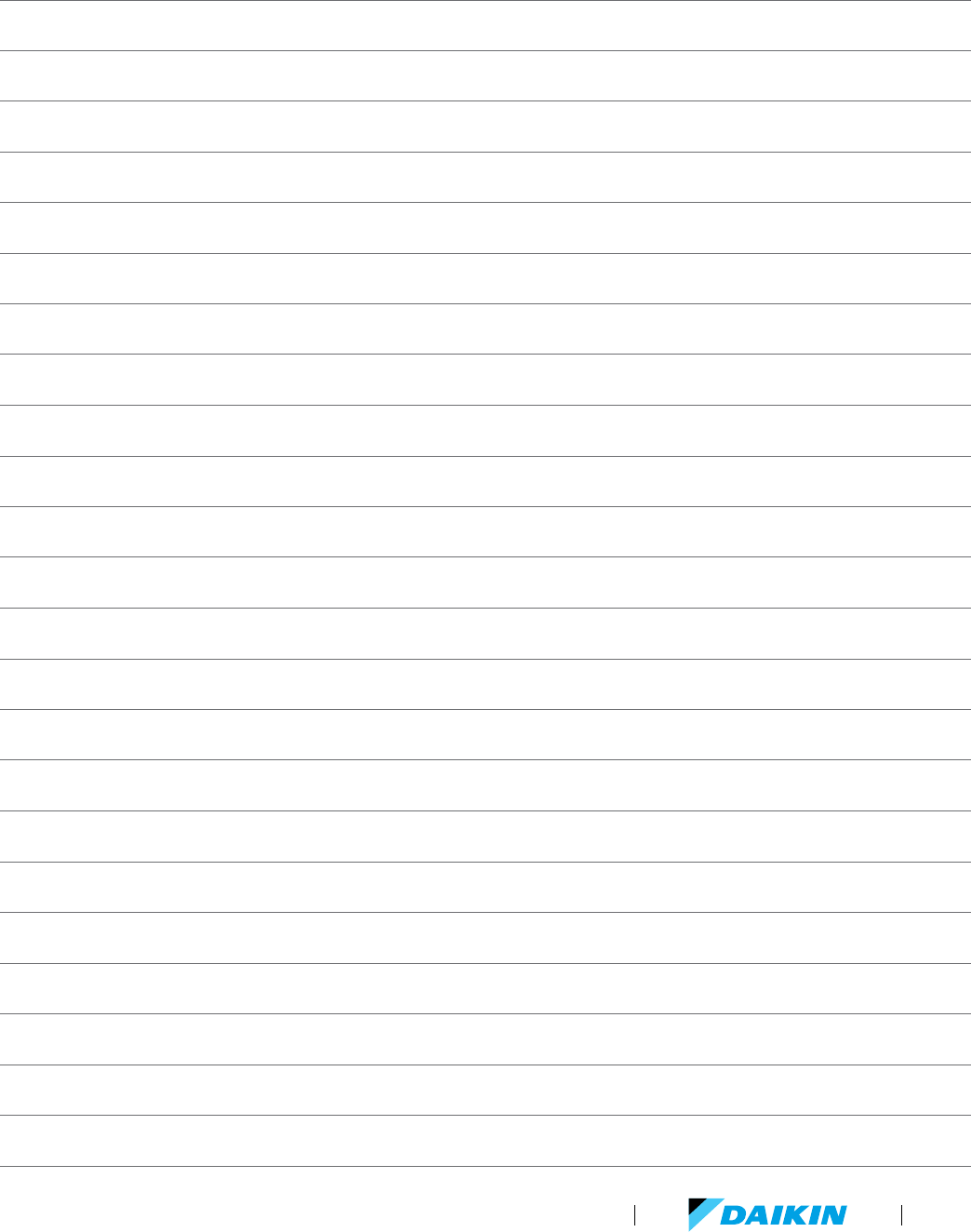
VRV Product Catalog
147

www.daikincomfort.com148

CT-VRV 08-15
COMMERCIAL
RENOVATION
NEW CONSTRUCTION
Before purchasing a appliance in this document, read important
information about its estimated annual energy consumption,
yearly operating cost, or energy efficiency rating that is available
from your retailer.
Daikin: The Premium Brand industry leader
Daikin Industries, Ltd. (DIL) is a global Fortune
1000 company which celebrated its 90th
anniversary in May 2014. The company is
recognized as the largest HVAC (Heating, Ventilating,
Air Conditioning) manufacturer in the world. DIL is
primarily engaged in developing indoor comfort products,
systems and refrigeration products for residential,
commercial and industrial applications. Its consistent
success is derived, in part, from a focus on innovative,
energy-efficient and premium quality indoor climate and
comfort management solutions.
WARNINGS:
Always use a licensed installer or contractor to install this
product. Do not try to install the product yourself. Improper
installation can result in water or refrigerant leakage, electrical
shock, fire or explosion.
Use only those parts and accessories supplied or specified
by Daikin. Ask a licensed contractor to install those parts and
accessories. Use of unauthorized parts and accessories or
improper installation of parts and accessories can result in
water or refrigerant leakage, electrical shock, fire or explosion.
Read the User’s Manual carefully before using this product.
The User’s Manual provides important safety instructions and
warnings. Be sure to follow these instructions and warnings.
For any inquiries, contact your local Daikin sales office.
Daikin, and its design, VRV and REFNET are trademarks of Daikin Industries, Ltd.
Our continuing commitment to quality products may mean a change in specifications without notice.
© 2015 · Houston, Texas · USA · www.daikincomfort.com